Table of Contents
Advertisement
Quick Links
Dear SHARP Customer
Welcome to the SHARP Family. We are pleased that you are now the owner of a SHARP Color
LCD Projector built for outstanding quality, reliability and performance.
Every SHARP Color LCD Projector is adjusted for a proper picture and has passed through the
most stringent quality control tests at the factory. We have prepared this OPERATION MANUAL
so that you have the ability to adjust the picture and color to your personal viewing preference.
We sincerely hope that you will be satisfied with the quality and performance of your Color LCD
Projector for many years to come.
Please read the instructions carefully, and keep them handy for future reference.
IMPORTANT
For your assistance in reporting the loss or
theft of your Color LCD Projector, please
record the Serial Number located on the rear
of the projector and retain this information.
Important Information
There are two important reasons for prompt warranty registration of your new SHARP LCD
Projector, using the REGISTRATION CARD packed with the projector.
1. WARRANTY
This is to assure that you immediately receive the full benefit of the parts, service and
labor warranty applicable to your purchase.
2. CONSUMER PRODUCT SAFETY ACT
To ensure that you will promptly receive any safety notification of inspection, modification,
or recall that SHARP may be required to give under the 1972 Consumer Product Safety
Act, PLEASE READ CAREFULLY THE IMPORTANT "LIMITED WARRANTY" CLAUSE.
U.S.A. ONLY
WARNING: High brightness light source. Do not stare into the beam of light, or view directly.
Be especially careful that children do not stare directly into the beam of light.
WARNING: To reduce the risk of fire or electric shock, do not expose this product to rain or
moisture.
CAUTION
RISK OF ELECTRIC SHOCK.
DO NOT REMOVE SCREWS
EXCEPT SPECIFIED USER
SERVICE SCREW.
CAUTION: TO REDUCE THE RISK OF ELECTRIC SHOCK,
DO NOT REMOVE COVER.
NO USER-SERVICEABLE PARTS EXCEPT LAMP UNIT.
REFER SERVICING TO QUALIFIED SERVICE
PERSONNEL.
E-1
Model No.: XG-NV2U
Serial No.:
The lightning flash with arrowhead symbol,
within an equilateral triangle, is intended to
alert the user to the presence of uninsulated
"dangerous voltage" within the product's
enclosure that may be of sufficient
magnitude to constitute a risk or electric
shock to persons.
The exclamation point within a triangle is
intended to alert the user to the presence of
important operating and maintenance
(servicing) instructions in the literature
accompanying the product.
Advertisement
Table of Contents

Related Manuals for Sharp XG-NV2U


Summary of Contents for Sharp XG-NV2U
- Page 1 Dear SHARP Customer Welcome to the SHARP Family. We are pleased that you are now the owner of a SHARP Color LCD Projector built for outstanding quality, reliability and performance. Every SHARP Color LCD Projector is adjusted for a proper picture and has passed through the most stringent quality control tests at the factory.
-
Page 2: Important Safeguards
WARNING: FCC Regulations state that any unauthorized changes or modifications to this equipment not expressly approved by the manufacturer could void the user’s authority to operate this equipment. INFORMATION This equipment has been tested and found to comply with the limits for a Class A digital device, pursuant to Part 15 of the FCC Rules. -
Page 3: Cautions Concerning The Laser Pointer
(including amplifiers) that produce heat. Cautions Concerning the Laser Pointer "COMPLIES WITH 21 CFR SUBCHAPTER J" CAUTION SHARP ELECTRONICS CORPORATION SHARP PLAZA, MAHWAH, NEW JERSEY 07430 TEL : 1-800-BE-SHARP LASER RADIATION- DO NOT STARE INTO BEAM REMOTE CONTROL MODEL NO. -
Page 4: Notes On Operation
Notes on Operation About the Temperature Monitor Function: • If the projector starts to overheat due to set-up problems or a dirty air filter, “TEMP.” will flash in the upper-left corner of the picture. If the temperature continues to rise, then the lamp will turn off, the TEMPERATURE WARNING indicator will flash, and after a 90-second cooling-off period the power will shut off. -
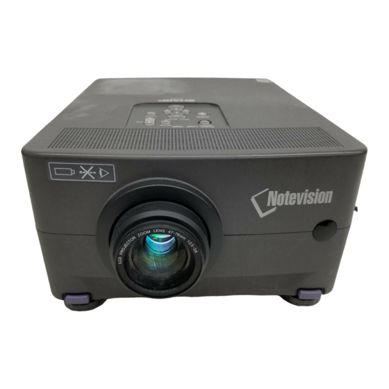
Page 5: Location Of Controls
Location of Controls FRONT VIEW Zoom ring Lens focusing ring Cooling fan (Intake vent) Cooling fan Carring handle (Exhaust vent) Security Lock Anchor This projector has a Kensington Security Standard connector for use with a Kensington MicroSaver Security System. Refer to the information that came with the system for instructions on how to use it to secure this model. -
Page 6: Operating The Wireless Mouse Remote Control
Operating the Wireless Mouse Remote Control The functions of your personal computer’s mouse have been built into the remote control enabling you to operate your projector and personal computer with the remote control. 1. Slide the MAIN POWER switch on the rear of the unit on. 2. - Page 7 LASER LIGHT WINDOW Laser light shines out of this window. "COMPLIES WITH 21 CFR SUBCHAPTER J" CAUTION SHARP ELECTRONICS CORPORATION SHARP PLAZA, MAHWAH, NEW JERSEY 07430 TEL : 1-800-BE-SHARP LASER RADIATION- DO NOT STARE INTO BEAM REMOTE CONTROL MODEL NO. : G1414CESA WAVE LENGTH : 670nm DC6V (1.5VX4PCS.)
-
Page 8: Wireless Mouse Functions
• Do not connect or remove the mouse control cables and computer control cable to/from your computer while it is on. This may damage your computer. • Only one set of connection cables is supplied with your projector. For additional connection cables, contact your nearest Authorized Sharp Industrial LCD Products Dealer or Service Center. -
Page 9: Setting Up The Projector
Setting Up the Projector Using the Focus and Zoom • Zoom, Focus and Reversed/Inverted Image mode functions broaden your options for projector placement. • See pages 10, 11 and 12 for details on projector setup. SIDE VIEW POWER LAMP POWER indicator Zoom ring (Lens housed) Lens focusing ring... - Page 10 Projector Distance and Picture Size Relationship • The zoom lens allows adjustment of the image size within the projector’s range. • For optimum picture adjustment, the projector should be placed and adjusted at a distance between 4.6 ft (1.4 m) and 57.4 ft (17.5 m) from the screen. Distance from screen Picture size: 100 inches (254 cm) Zoom adjustment range: 19.0 ft–11.8 ft...
-
Page 11: Using The Image Invert/Reverse Function
Cautions: When setting up the projector • For minimal servicing and to maintain high image quality, SHARP recommends that this projector be installed in an area free from humidity, dust and cigarette smoke. When the projector is subjected to these environ- ments, the lens and filter must be cleaned more often. - Page 12 Example of a ceiling-mount setup Before mounting the projector, be sure to contact your nearest Authorized Sharp Industrial LCD Products Dealer to obtain the manufacturer recommended ceiling mount bracket (sold separately). (AN-XGCM40 Ceiling Mount Bracket, AN-EP101AP Extension Tube for AN-XGCM40.)
-
Page 13: Adjusting The Height Of The Picture
Adjusting the Height of the Picture Use the adjuster release to adjust the angle of the projector and height of the picture. Minor adjustments can be made with the adjusters. Adjuster release Adjusters Transporting the Projector Use the carrying handle when carrying the projector. When transporting the projector, carry it by the handle located on the side of the unit. -
Page 14: Connecting The Projector (Video 1, Video 2)
Connecting the Projector (VIDEO 1, VIDEO 2) To playback audio and video with the projector connected to a VCR, Laser Disc Player or external audio amplifier, make the following connections. • Always turn off the LCD Projector while connecting to video equipment, in order to protect both the projector and the equipment being connected. -
Page 15: Connecting The Projector (Rgb 1, 2: Computer)
Connecting the Projector (RGB 1, 2: Computer) • Please carefully read the manual of the computer you will be con- necting. • Before connecting, be sure to turn both the projector and the computer off. After making all connections, turn the projector on first. The com- puter should always be turned on last. - Page 16 Connecting to the Computer RGB Input (RGB 1, 2)/Output Terminals You can connect your projector to a computer for easy projection of full-color computer images, and an external monitor for simultaneous viewing. Rear view of the projector COMPUTER RGB IN 1 IN 2 RGB Signal Input Socket...
-
Page 17: Connecting An External Monitor
COMPUTER AUDIO IN 2 IN 1 AUDIO OUTPUT PC CONTROL COMPUTER RGB IN 1 Direct connection External IBM-PC monitor E-17 3. Connecting to other compatible computers When connecting the projector to a compatible computer other than an IBM-PC (VGA/SVGA/XGA) or Macintosh series, a separate cable may be needed. -
Page 18: Input Signals (Recommended Timing)
Input Signals (Recommended Timing) For IBM and compatibles Input signals: The video output signal timing of different types of video signals are shown below for reference. VIDEO SIGNAL HORIZONTAL SYNC SIGNAL VIDEO SIGNAL VERTICAL SYNC SIGNAL Text 720 dots 350 lines 400 lines 350 lines 400 lines 480 lines 480 lines R •... -
Page 19: Rgb Adjustment Controls
RGB Adjustment Controls When displaying computer patterns which repeat every other dot (tiling, vertical stripes, etc.), interference may occur between the LCD pixels, causing flickering, vertical stripes, or contrast irregularities in portions of the screen. Should this occur, use the ADJUSTMENT ß/© buttons for HORIZONTAL (LEFT/RIGHT) and VERTICAL (UP/DOWN) position adjustments to adjust for the optimum picture. -
Page 20: Computer Mode Memory Adjustments
When RGB 1 or 2 is selected. On-Screen Display R G B 1 A D J . R G B 1 I N P U T A D J . I M A G E A D J . A U D I O S Y S T E M S E T U P L A N G U A G E : S E L . -
Page 21: Basic Operation Of The Projector
Basic Operation of the Projector 110-120V/ 200-240V~ POWER When the MAIN POWER is on, the POWER indicator lights red. Projector Remote control ON/OFF ON/OFF POWER LAMP When the power is on, the LAMP REPLACEMENT indicator flashes to show the operating condition of the lamp. -
Page 22: Setting The On-Screen Display Language
On-Screen Display L A N G U A G E E N G L I S H D E U T S C H E S P A Ñ O L N E D E R L A N D S F R A N Ç... - Page 23 On-Screen Display For viewing the picture from a video source connected to: VIDEO INPUT 1 VIDEO INPUT 2 COMPUTER RGB1 COMPUTER RGB2 The number of displayed segments (0–60) increases or decreases as the volume is raised or lowered. V O L U M E POWER LAMP E-23...
-
Page 24: Adjusting The Picture
Adjusting the Picture On-Screen Display R G B 1 A D J . R G B 1 I N P U T A D J . I M A G E A D J . A U D I O S Y S T E M S E T U P L A N G U A G E : S E L . -
Page 25: Adjusting The Audio
Adjusting the Audio On-Screen Display A U D I O B A L A N C E T R E B L E B A S S R E S E T : S E L . : A D J . MENU : E N D E-25... -
Page 26: Functions On The Projector
Functions on the Projector On-Screen Display S Y S T E M S E T U P R E S O L U T I O N 8 0 0 @ 6 0 0 H O R F R E Q 3 7 . - Page 27 LCD Projector BLACK SCREEN On-Screen Display I M A G E A D J . B L K S C R N D I S P I N P U T D I S P L A Y R E V E R S E I N V E R T : S E L .
-
Page 28: Using The Blue Screen Function
On-Screen Display I M A G E A D J . B L U E S C R E E N B L K S C R N D I S P O F F I N P U T D I S P L A Y O F F S Y S T E M R E V E R S E... -
Page 29: Air Filter Maintenance
• The air filter should be cleaned every 100 hours of use. Clean the filter more often when the projector is used in a dusty or smoky location. • Have your nearest Authorized Sharp Industrial LCD Products Dealer or Ser- vice Center exchange the filter (PFILD0069CEZZ) when it is no longer pos- sible to clean it. -
Page 30: Lamp/Maintenance Indicators
Note: The lamp usage time can be checked with the On-Screen display. (See page 26.) • If the new lamp does not light after replacement, take your projector to the nearest Authorized Sharp Industrial LCD Products Dealer or Service Center for repair. -
Page 31: Lamp Replacement
Authorized Sharp Industrial LCD Products Dealer. Then change the lamp by carefully following the instructions below. If you wish, you may bring the projector to your nearest Authorized Sharp Industrial LCD Products Dealer. IMPORTANT NOTE TO U.S. CUSTOMERS: The lamp included with this projector is backed by a 90-day parts and labor limited warranty. All service of this projector under warranty, including lamp replacement, must be obtained through an Authorized Sharp Industrial LCD Products Dealer or Service Center. -
Page 32: Resetting The Lamp Timer
Installing the lamp unit 1. Hold the lamp cage (i) by the handle (h) and press it in firmly while making sure that grooves on the side of the lamp cage (j) are properly aligned with the projections inside the lamp cage compartment, and that the holes on the top of the lamp cage (k) are aligned with the screw holes on the projector. -
Page 33: Connection Pin Assignments
Connection Pin Assignments Analog RGB 1 and 2 Signal Input and Analog RGB Output Terminal: D-sub female connector Mouse Input Terminal (for IBM/Mac): Pin No. Mouse Input Terminal (for NEC PC98 series for Japan): Pin No. RS-232C terminal: 9-pin D-sub male connector Pin No. -
Page 34: Rs-232C Terminal Specifications
RS-232C Terminal Specifications 1. PC control A personal computer can be used to control the projector by connecting the supplied computer control cable to the PC CONTROL 1 terminal on the projector and an RS-232C cable (cross type) (not supplied) to the computer, and then connecting the RS-232C cable to the computer control cable. - Page 35 COMMAND PARAMETER CONTROL ITEM VOLUME ADJUSTMENT AUDIO ADJUSTMENT RGB 1 ADJUSTMENT RGB 2 ADJUSTMENT RGB INPUT ADJUSTMENT SCREEN SETTING VIDEO CONFIRMATION ON-SCREEN DISPLAY SETTING MOUSE ADJUSTMENT SCREEN MODE MEMORY Note: • RGB INPUT ADJUSTMENT can only be set in the displayed computer mode. Example: When BRIGHT of RGB 1 IMAGE ADJUSTMENT is set to Computer...
-
Page 36: Wired Remote Control Terminal Specifications
VIDEO 1 VIDEO 2 RGB1 RGB 2 ENTER INPUT CHECK BLACK SCREEN 3. Sharp remote control signal format 1. Transmission format a. 15-bit format 67.5 ms 67.5 ms 2. Wave form of output signal • Output using Pulse Position Modulation “1”... -
Page 37: Specifications
(QACCU5013CEZZ) This will not affect the picture quality or the life expectancy of the unit. RGB) TFTs (Thin Film If you have any questions about this matter, please call toll free 1-800- BE-SHARP (1-800-237-4277). U.S.A. ONLY 624 [V]) terminated (stereo) - Page 38 Dimensions Rear View Top View (Lens housed) Side View (Lens extended) 10.3 (261) 0.2 (5) 1.1 (29) Front View 8.0 (204) Bottom View [Units: inches (mm)] E-38...