Table of Contents
Advertisement
Available languages
Available languages
Owner's Manual
CRRFT$14Rli °
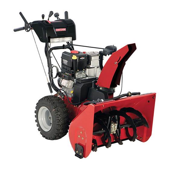
SNOW THROWER
1450 Series Briggs and Stratton Engine
Power-Propelled
30" Two-Stage
Model No.
917.881064
• Espafiol, p. 21
CAUTIO
."
Read and follow all
Safety Rules and Instructions
before operating this equipment
Sears, Roebuck and Co., Hoffman Estates, IL 60179 U.S.A.
Visit our Craftsman
website:
www.sears.com/craftsman
Advertisement
Table of Contents

Related Manuals for Craftsman 917.881064


Summary of Contents for Craftsman 917.881064
- Page 1 1450 Series Briggs and Stratton Engine Power-Propelled 30" Two-Stage Model No. 917.881064 • Espafiol, p. 21 CAUTIO ." Read and follow all Safety Rules and Instructions before operating this equipment Sears, Roebuck and Co., Hoffman Estates, IL 60179 U.S.A. Visit our Craftsman website: www.sears.com/craftsman...
- Page 2 Safe Operation This snow thrower is capable of amputating hands and feet and throwing objects. Failure to observe the following safety instructions could result in serious injury. & Look for this symbol to point out ira= portant safety precautions. CAUTION!!! BECOMEALERT!!! SAFETY IS INVOLVED.
- Page 3 6. Whencleaning, repairingorinspectingthesnowthrower, stoptheengine andmakecertain thecollector/impel- ler andall moving parts havestopped.Disconnect thesparkplugwireandkeepthewireaway fromthe plug. toprevent someone f romaccidentally starting the engine. 7. Donot runthe engine indoors, e xcept w henstarting theengine andfortransporting thesnowthrower i nor outof thebuilding. O pentheoutside doors; e xhaust fumes aredangerous.
- Page 4 30 days of purchase, but a trip charge will apply. This charge will be waived if you transport the product to an authorized Craftsman drop-off location. For the nearest authorized location, call 1-800-4-MY-HOME®.
- Page 5 PARTS PACKE (1) POWER (198583) _1111111 (1) DISCHARGE CHUTE EXTRA SHEAR BOLTS AND NUTS (2) SHOULDER BOLT 1/4=20 x 1=3/4 ROTATOR HEAD MOUNTING (1) WASHER (19131316) CHUTE DEFLECTOR REMOTE CONTROL (1) LOCKNUT (1) CARRIAGE BOLT 5/16-18 5/16=18 x 5/8 (751153) (72250505) (2) FLAT WASHERS ELY I...
- Page 6 ASSE Read these instructions and this manual in its entirety before you attempt to assemble or operate your new snow thrower. Reading the entire manual will familiar- ize you with the unit, which will assist you in assembly, operation and maintenance of the product.
- Page 7 iNSTALL TRACTION DRIVE CONTROL ROD (See Figs. 3 and 4) The traction drive control rod has the long loop on the end of the spring as shown. Slide rubber sleeve up rod and hook end of spring into pivot bracket with loop opening down as shown. With top end of rod positioned under left side of control panel, push rod down and insert top end of rod intohole in drive control bracket.
- Page 8 ASSE iNSTALL DISCHARGE CHUTE / CHUTE HEAD (See Fig. 7) NOTE: The multi-wrench provided in your parts bag may be used to install the chute rotator head. Place discharge chute assembly on top of chute base with discharge opening toward front of snow thrower. Position chute rotator head over chute bracket.
- Page 9 KNOW YOUR SNOW THROWER READ THIS OWNER'S MANUALAND the illustrations with your snow thrower to familiarize yourself with the location of various controls and adjustments. this manual for future reference. These symbols may appear on your snow thrower or in literature their meaning.
- Page 10 GASOLINE CONTROL SAFETY iGNiTiON ON / OFF SWITCH NOTE: iTEMS ABOVE ARE SHOWN iN THEIR TYPICAL LOCATION ON THE ENGINE. ACTUAL LOCATION MAY VARY WITH THE ENGINE ON YOUR UNIT, AUGERS MEETS A.N.S.I. SAFETY REQUIREMENTS Our snow throwers conform to the standards of the American National Standards Institute. Toolbox = used to store spare shear bolts, locknuts and wrench.
- Page 11 The operation of any snow thrower can result in foreign objects thrown intothe eyes, which can result in severe eye damage. Always wear safety glasses or eye shields while operating your snow thrower or performing any adjust- ments or repairs. We recommend standard safety glasses or a wide vision safety mask worn over spectacles.
- Page 12 TO THROW SNOW (See Fig. 13) The auger rotation is controlled by the auger control lever located on the right side handle. • Squeeze auger control lever to handle to engage the auger and throw snow. • Release the auger control lever to stop throwing snow. AUGER CONTROL LEVER...
- Page 13 TO ADJUST SKID PLATES (See Fig. 17) NOTE: The wrench provided in your parts bag may be used to adjust the skid plates. Skid plates are located on each side of the auger housing and adjust the clearance between the scraper bar and the ground surface.
- Page 14 TO START ENGINE Your snow thrower engine is equipped with both a 120 Volt A.C. electric starter and a recoil starter. The electric starter is equipped with a three-wire power cord and plug and is designed to operate on 120 Volt A.C. household current. •...
- Page 15 MAINTENANCE FILL IN DATES AS YOU COMPLETE REGULAR SERVICE Check for Loose Fasteners Clean / Inspect Snow Thrower Check/Replace V=Belts RE Lubrication Chart Check Engine Oil Level Change Engine Oil Inspect Muffler Check / Replace Spark Plug Empty Fuel Tank GENERAL RECOMMENDATIONS The warranty on this snow thrower does not cover items...
- Page 16 V-BELTS Check V-belts for deterioration and wear after every 50 hours of operation and replace if necessary. The belts are not adjustable. Replace belts if they begin to slip from wear. (See "TO REMOVE BELT COVER" in the Service and Adjustments section of this manual). The V-belts on your snow thrower are of special construction and should be replaced by original equipment manufacturer (OEM) belts available from your nearest dealer.
- Page 17 WARNING: To avoid serious performing any service or adjustments: 1. Be sure the on/off switch is in the OFF position. 3. Make sure the augers and all moving 2. Remove safety ignition key. parts have completely stopped. 4. Disconnect spark plug wire from spark plug and place wire where it cannot come in contact with plug.
- Page 18 SERVICE A TO REPLACE BELTS (See Fig. 22) The auger and traction drive belts are not adjustable. If the belts are damaged or begin to slip from wear, they should be replaced. It is recommended that the belt(s) be replaced by a Sears service centre/department.
- Page 19 TOREMOVE WHEELS (SeeFig.23) Remove t heklikpinandremove wheel f romaxle. IMPORTANT: When installing wheel, be sure to use the axle hole closest to the end of the shaft - do not use the hole in the wheel hub (if equipped). hole in wheel hub are not used for your model snow thrower. KLIK PiN (iNSTALL iN OUTER HOLE OF AXLE ONLY)
- Page 20 TROUBLESHOOTI See appropriate section in manual unless directed PROBLEM CAUSE Does not start Fuel shut-off valve (if so equipped) in OFF position. Safety ignition key is not inserted. Out of fuel. Throttle in STOP position (or ON/OFF switch is OFF). Choke in OFF position.
- Page 21 Procedimientos Esta m&quina puede amputar manos y pies y lanzar objetos. El no observar las siguientes instrucciones de seguridad puede dar lugar a heridas graves. Busque este simbolo _ala precaueiones ridad de ,importancia. iATENCION! iESTE SEGURIDAD ESTA COMPROMETIDA. ADVERTENCIA: Siempre desconecte el &...
- Page 22 (g) Reponer e ltap6n decarburante f irmemente y se- carelcarburante d erramado. (h) Siel carburante s ederrama s obre vestidos, c am- biarlos inmediatamente. 5. Para todas lasunidades conmotores d emando e l6ctrico odeencendido el@ctrico, usar c ables deprolongamiento y receptficulos especificados porelfabricante. 6.
- Page 23 NIEVES. DEBE REGISTRAR TANTO EL NUMERO COME LA FECHA DE COMPRA Y MANTENGALOS UN LUGAR SEGURO PARA REFENCIA EN EL FUTURO. DEL LANZADOR DE NIEVE CRAFTSMAN de acuerdo alas instrucciones o de fabricaci6n para gestionar su reparaci6n sin cargo. el servicio de los primeros 30 dias, pero se le cobrar&...
- Page 24 PARTES EMPACADAS ALIMENTACION (1) CONDUCTO LA DESCARGA PERNOS Y TURCAS EXTRA PARA LA CIZALLA (2) PERNO RESALTO SOPORTE DE CABEZA GIRATORIA (1) ARANDELA (19131316) MANDO A D|STANC|A DEL DEFLECTOR DEL CONDUCTO (1) TUERCA (1) PERNO SEGURIDAD ACARREO 5/16-18 5/16-18 × 5/8 (751153) (72250505) (2) ARANDELAS...
- Page 25 MONTAJE / PRE-OPE Leer estas instrucciones y este manual completamente antes de empezar a montar o hacer fu ncionar su nuevo quitanieves. La lectura del manual le familiarizara con la unidad, Io cual le asistira en el montaje, la operaci6n del producto.
- Page 26 MONTAJE / PRE-OPERACI MONTAJE DE LA BIELA DE IVlANDO DE LA TRACCION La bieta de mando de la tracci6n tiene un gancho largo en et extremo det resorte, como mostrado. 1. Destizar et manguito de caucho sobre la bieta y enganchar la terminaci6n det resorte en el soporte det pivote con et gancho abierto hacia abajo como mostrado.
- Page 27 MONTAJE / PRE-OPE MONTAR EL CONDUCTO DE EYECCION GIRATORIA DEL CONDUCTO NOTA: la Ilave de apriete proporcionada en su botsa de partes se puede utilizar para instalar la cabeza giratoria del conducto. 1. Cotocar el grupo del conducto de eyecci6n sobre la base det conducto con la abertura de eyecci6n m&quina quitanieves.
- Page 28 FAMILIARJCESE CON SU MAQUINA LEA ESTE MANUAL DEL DUENO Y LAS REGLAS DE SEGURIDAD Compare las ilustraciones con su segadora para familiarizarse con ta ubicaci6n de los diversos controles y ajustes. Guarde este manual para referencia en et futuro. Estos sJmbolos pueden apareser sobre su m_quJna quJtanJeves o en la literatura proporcionada comprenda sus signJficados.
- Page 29 DEPOSITO DE GASOLINA SILEN- CIADOR CON- TROL DE LA ESTRA- NGU- LACION CEBADOR LLAVE DE ENCENDIDO SEGURIDAD INTERRUPTOR DE ON/OFF HERRAMIENTA NOTA:LAS PARTES MOSTRADAS ARRIBA SE ENCUENTRAN SU TiPICA POSICION EN EL MOTOR. LA POSICION REAL PUEDEVARIAR DEPENDIENDO DEL MOTOR EN SU UNIDAD.
- Page 30 La operaci6n de cualquier m&quina quitanieves puede hacer que salten objetos extraflos dentro $EGURIDAD de sus ojos, Io que puede producir daflos graves en estos. Siempre use anteojos o protecci6n para los ojos mientras m&quina quitanieves o cuando haga ajustes o reparaciones.
- Page 31 LANZAR LA NIEVE (Vet Fig. 13) La rotaci6n de la barrena se controla con ta palanca de mando de la barrena posicionada en la empufladura Apretar la palanca de mando de la barrena hacia la empufla- dura para conectar la barrena y lanzar nieve. Soltar la palanca de mando de la barrena para parar de lanzar nieve.
- Page 32 REGULAR LAS PLACAS DE DESLIZAMIENTO (Vet Fig. 17) NOTA: la Ilave de apriete proporcionada puede utitizarse para regular las ptacas de deslizamiento. Las placas de deslizamiento est&n posicionadas del alojamiento de la barrena y regutan la distancia barra de arrastre y et suelo. Regute las placas de deslizamiento uniformemente a la altura apropiada superficie.
- Page 33 PUESTA EN IVIARCHA DEL MOTOR El motor de su m&quina quitanieves est& equipado tanto con un arrancador electrico de 120 Voltios A.C. como con un arrancador de retroceso. El arrancador etectrico est& equipado con un cable de potencia de tres hilos y un enchufe y est& proyectado para que funcione con corriente domestica de 120 Vottios A.C.
- Page 34 Revisar si hay Sujetadores Sueltos Limpiar / Inspeccionar el m&quina quitanieves Cambiar / Revisar las Correas Lubricaci6n Revisar el nivel del Aceite Cambiar el Aceite del motor Inspeccionar el Silenciador Cambiar / Revisar la Bujia Vaciar el Dep6sito del Combustible RECOMENDACIONES GENERALES La garantia de esta maquina quitanieves no cubre los articutos...
- Page 35 MAQUINA QUITANIEVES Siempre observe las regtas de seguridad cuando haga et man- tenimiento. LLANTAS • Mantener la presi6n adecuada en ambos neumaticos (14-17 RS.I. / 19-24.5 N-m). • Mantenga las Ilantas sin gasolina o aceite, que pueden daflar la goma. NOTA: Para setlar los neumaticos y prevenir neumaticos desin- flados a causa de perdidas tigeras, se puede comprar setlador al efecto en el revendedor de partes local.
- Page 36 ERVlCIO Y ADJUSTES ADVERTENCIA: Para evitar lesi6nes serias, an= tes de dar calquier servico o de hater ajustes: 1. Asegurarse de que el interruptor de ON/OFF est_ en la posici6n OFF. 2. Quitar la Ilave de encendido de segu= ridad. Aseg_rese la barrenas las partes movibles se hayan detenido...
- Page 37 ERVlCIO Y ADJUSTES SUSTITUIR LAS CORREAS (Vea Fig. 22) Las correas de la barrena y de la tracci6n no se pueden regular. Si las correas est&n dafladas o empiezan a resbalar por el desgaste, se tendHan que sustituir. Se recomienda que la(s) correa(s) sean sustituidas por et Centro de Piezas y Reparaci6n Sears.
- Page 38 DESMONTAR LAS RUEDAS (Vet Fig. 23) • Desmontar el perno de lingOete y desmontar la rueda det eje. IMPORTANTE: Cuando se montan las ruedas, asegurarse de que se use et orificio det eje m&s cercano al extremidad del arbol. - no utilizar et orificio en et cubo de la rueda, si provisto. Los orificios internos det eje y del cubo de la rueda no se usan para este modeto de m&quina quitanieves.
- Page 39 I ENTIFICACl Vea la secci6n apropiada en el manual amenos que est6 dirigido a un Centro de Piezas y Reparaci6n Sears. CAUSA PROBLEMA 1. VAlvula del combustible estA OFR No arranca La Ilave de encendido de seguridad no estA puesta. Sin combustible.
- Page 40 REPAIR PARTS SNOW THROWER - - MODEL NUMBER 917,881064 AUGER HOUSING / iMPELLER ASSEMBLY 2 (EXPLODED) 01.07.004-B...
- Page 41 REPAIR PARTS AUGER HOUSING /iMPELLER NOTE: All component dimensions given in U.S. inches. iMPORTANT: Use only Original Equipment Manufacturer (O.E.M.) replacement parts. Failure to do so could be hazardous, damage your snow thrower and void your warranty. SNOW THROWER - - MODEL NUMBER ASSEMBLY PART DESCRIPTION...
- Page 42 REPAIR PARTS AUGER HOUSING / iMPELLER ASSEMBLY NOTE: All component dimensions given in U.S. inches. iMPORTANT: Use only Original Equipment Manufacturer (O.E.M.) replacement parts. Failure to do so could be hazardous, damage your snow thrower and void your warranty. SNOW THROWER - - MODEL NUMBER 917,881064 PART 404930X615...
- Page 43 REPAIR PARTS AUGER HOUSING /iMPELLER 01.07.024-B NOTE: All component dimensions given in U.S. inches. iMPORTANT: Use only Original Equipment Manufacturer (O.E.M.) replacement parts. Failure to do so could be hazardous, damage your snow thrower and void your warranty. SNOW THROWER - - MODEL NUMBER ASSEMBLY 420478...
- Page 44 REPAIR PARTS AUGER HOUSING / iMPELLER ASSEMBLY NOTE: All component dimensions given in U.S. inches. iMPORTANT: Use only Original Equipment Manufacturer (O.E.M.) replacement parts. Failure to do so could be hazardous, damage your snow thrower and void your warranty. SNOW THROWER - - MODEL NUMBER 917,881064 PART 72270506...
- Page 45 REPAIR PARTS CONTROL PANEL / DISCHARGE PART DESCRIPTION CHUTE WELDMENT 404770X615 DEFLECTOR WELDMENT 178833X615 DEFLECTOR CONTROL ASSEMBLY 420873 DEFLECTOR SEAL 420325 KNOB BLACK 414280 POP RIVET 128415 SCREW 10-24 X .625 17501010 SHOULDER SCREW 179829 PLASTIC WASHER 179246 "10 191730 NUT 1/4-20 "11 72250505...
- Page 46 REPAIR PARTS CONTROL PANEL / DISCHARGE PART DESCRiPTiON LEVER/CABLE 420337 SCREW 10-24 X .825 17501010 ROTATOR HEAD 420878 ROTATOR PIVOT BRACKET 420877 PULLEY PIVOT 420875 CABLE ASSEMBLY "8 420874 NOTES: 1. ITEMS INDICATED WITH AN * ARE LISTED AS REFERENCE FOR SERVICE PARTS ONLY. PART DESCRIPTION 188303...
- Page 47 REPAIR PARTS HANDLES NOTE: All component dimensions given in U.S. inches. iMPORTANT: Use only Original Equipment Manufacturer (O.E.M.) replacement parts. Failure to do so could be hazardous, damage your snow thrower and void your warranty. SNOW THROWER - - MODEL NUMBER 917,881064 PART DESCRIPTION 412683X479...
- Page 48 REPAIR PARTS HANDLES NOTE: All component dimensions given in U.S. inches. iMPORTANT: Use only Original Equipment Manufacturer (O.E.M.) replacement parts. Failure to do so could be hazardous, damage your snow thrower and void your warranty. SNOW THROWER - - MODEL NUMBER 917,881064 PART 419798X479 419799X479...
- Page 49 REPAIR PARTS HANDLES NOTE: All component dimensions given in U.S. inches. iMPORTANT: Use only Original Equipment Manufacturer (O.E.M.) replacement parts. Failure to do so could be hazardous, damage your snow thrower and void your warranty. SNOW THROWER - - MODEL NUMBER 917,881064 PART 412675X004 414572...
- Page 50 NOTE: All component dimensions given in U.S. inches. iMPORTANT: Use only Original Equipment Manufacturer (O.E.M.) replacement parts. Failure to do so could be hazardous, damage your snow thrower and void your warranty. SNOW THROWER - - MODEL NUMBER 917.881064 PART 180480 405740 180445...
- Page 51 REPAIR PARTS DRIVE 01.03.002-A NOTE: All component dimensions given in U.S. inches. iMPORTANT: Use only Original Equipment Manufacturer (O.E.M.) replacement parts. Failure to do so could be hazardous, damage your snow thrower and void your warranty. SNOW THROWER - - MODEL NUMBER 917,881064 PART DESCRIPTION 404923...
- Page 52 REPAIR PARTS SNOW THROWER - - MODEL NUMBER 917,881064 DRIVE ITEM 43 EXPLODED. _ z / ... _ 69.,, \ \ \ .33"24 _23_...
- Page 53 REPAIR PARTS DRIVE PART DESCRIPTION 198474 SPEED SELECTOR ASSEMBLY 17501010 SCREW 10-24 X .625 402685X615 END PLATE 17490508 SCREW 5/16-18 X .50 57079 WASHER 405485 CONTROL ARM 198580 CLEVIS PIN 403097X004 SHIFTER PLATE 402881 SHOULDER BOLT 403096X004 SHIFTER BRACKET 191730 NUT 1/4-20 402856X004 CLUTCH PLATE...
- Page 54 REPAIR PARTS CHASSIS / ENGINE / PULLEYS NOTE: All component dimensions given in U.S. inches. IMPORTANT: Use only Original Equipment Manufacturer (O.E.M.) replacement parts. Failure to do so could be hazardous, damage your snow thrower and void your warranty. SNOW THROWER - - MODEL NUMBER 917,881064 PART DESCRiPTiON...
- Page 55 REPAIR PARTS CHASSIS / ENGINE / PULLEYS NOTE: All component dimensions given in U.S. inches. iMPORTANT: Use only Original Equipment Manufacturer (O.E.M.) replacement parts. Failure to do so could be hazardous, damage your snow thrower and void your warranty. SNOW THROWER - - MODEL NUMBER PART 192213...
- Page 56 REPAIR PARTS WHEELS _'-2 01.15.001-A NOTE: All component dimensions given in U.S. inches. IMPORTANT: Use only Original Equipment Manufacturer (O.E.M.) replacement parts. Failure to do so could be hazardous, damage your snow thrower and void your warranty. SNOW THROWER - - MODEL NUMBER 917,881064 PART DESCRIPTION 405161...
- Page 57 REPAIR PARTS WHEELS 01.15.003-A NOTE: All component dimensions given in U.S. inches. iMPORTANT: Use only Original Equipment Manufacturer (O.E.M.) replacement parts. Failure to do so could be hazardous, damage your snow thrower and void your warranty. SNOW THROWER - - MODEL NUMBER 917,881064 01.06.006-A PART DESCRIPTION...
- Page 58 REPAIR PARTS BAG OF PARTS s-._ 0t.t4.001-A 01.14.007-A NOTE: All component dimensions given in U.S. inches. iMPORTANT: Use only Original Equipment Manufacturer (O.E.M.) replacement parts. Failure to do so could be hazardous, damage your snow thrower and void your warranty. SNOW THROWER - - MODEL NUMBER 917,881064 _'N-13...
- Page 59 Failure to do so could be hazardous, damage your snow thrower and void your warranty. SNOW THROWER - - MODEL NUMBER 917,881064 PART DESCRIPTION DECAL, DANGER 181038 DECAL, CRAFTSMAN, 421233 DECAL, DANGER, DEFLECTOR 181034 DECAL, DANGER 181041 DECAL, CRAFTSMAN 421232...
- Page 60 BRIGGS & STRATTON 3O7 '% 1523 I <_, h--_ K_ q /842 1351 287 _ _--_ J_"_ 1298 1095 VALVE GASKET SET 51Aq 868 , _, 4-CYCLE ENGINE 3061 ... 741\ 1329 REPLACEMENT 1022 MODEL NUMBER 20M314-0927-E1 ENGINE t 48 SHORT BLOCK 358 ENGINE GASKET SET 1022 718A...
- Page 61 BRIGGS & STRATTON " 95 _L 51A( 975_ 4-CYCLE ENGINE :::;::::::::: 121 CARBURETOR 104 <C% 105 _ 117 th 369 _ 977 CARBURETOR 105 _ 1127 MODEL NUMBER 20M314-O927-E1 1171 13 c_¢('_- 383 _-V {\/_J 337 _"_"" 635 , ... --../, OVERHAUL 127 _...
- Page 62 BRIGGS & STRATTON 4-CYCLE ENGINE MODEL NUMBER 20M314-0927-E1 1251A " 1196 1288 1036 EMISSIONS LABEL 1011 1352 528 t_ 1211 1005 1070 1119 334 _ 190 _...
- Page 63 BRIGGS & STRATTON 4-CYCLE ENGINE MODEL NUMBER 20M314-0927=E1 123O 78 _ 615 @ <__ 604A...
- Page 64 BRIGGS & STRATTON PART DESCRiPTiON 794849 Cylinder Assembly 698340 Kit-Bushing!Seal 391086s • Seal-Oil (Magneto Side) 794871 Head-Cylinder 694872 "+ Gasket-Cylinder Tube-Breather 696750 Gasket-Crankcase 694953 • 794829 Screw (Cylinder Head) 695757 Plug-Oil Drain 691686 Plug-Oil Drain Crankshaft 794720 Cover-Crankcase 791965 698340 Kit-Bushing!Seal 391086s •...
- Page 65 BRIGGS & STRATTON PART DESCRiPTiON 613A 794844 Screw (Muffler) Retainer-Governor 694676 Crank-Governor 694675 695917 Spring!Link-Mechanical Governor Seal-Choke/Throttle 690998 691909 Boot-Spark Plug 699854 Screw (Control Panel) 794539 Spacer Deflector-Muffler 697816 699776 Screw (Muffler Deflector) 691855 Spring-Friction 795012 Screw (Starter Motor) 690959 Pin-Locating 718A 695178...
- Page 66 SERVICE OTES...
- Page 67 SERVICE NOTES...
- Page 68 For repair - in your home - of all major brand appliances, lawn and garden equipment, no matter For the replacement owner's For Sears professional and items like garage 1-800-4-MY-HOME For repair of carry-in and electronics, 1-800-488-1222 To purchase a protection agreement (U.S.A.) or maintenance 1-800-827-6655 Para pedir servicio de reparaci6n...