
Related Manuals for ABB ACS800-31


Summary of Contents for ABB ACS800-31
- Page 1 — ABB INDUSTRIAL DRIVES ACS800-31 drives (5.5 to 110 kW) ACS800-U31 drives (7.5 to 125 hp) Hardware manual...
- Page 2 — List of related manuals Drive hardware manuals and guides Code (English) ACS800-31/U31 Drives Hardware Manual (5.5 to 110 kW, 7.5 to 125 hp) 3AFE68599954 Drive firmware manuals and guides ACS800 Standard Control Program 7.x Firmware Manual and 3AFE64527592 Adaptive Program Application Guide...
- Page 3 ACS800-31 drives (5.5 to 110 kW) ACS800-U31 drives (7.5 to 125 hp) Hardware manual Table of contents 1. Safety instructions 4. Mechanical installation 6. Electrical installation 11. Start-up and use Rev C 3AFE68599954 EFFECTIVE: 2023-12-01 2023 ABB. All Rights Reserved.
-
Page 5: Table Of Contents
Table of contents 5 Table of contents 1. Table of contents 2. Safety instructions What this chapter contains ........... 11 Use of warnings and notes . - Page 6 6 Table of contents Checking the delivery ............36 Moving the unit .
- Page 7 Table of contents 7 Protecting the relay output contacts and attenuating disturbances in case of induc- tive loads ..............65 Selecting the control cables .
- Page 8 95 HARDWARE SPECIF ............108 ACS800-31/U31 specific parameters in the IGBT Supply Control Program ..109 Terms and abbreviations .
- Page 9 31 AUTOMATIC RESET ............110 Fixed parameters with the ACS800-31 and ACS800-U31 ..... 111 14.
- Page 10 How to select the correct drive/chopper/resistor combination ....145 External brake chopper and resistor(s) for the ACS800-31/U31 ....146 Brake chopper and resistor installation .
-
Page 11: Safety Instructions
Safety instructions 11 Safety instructions What this chapter contains This chapter contains the safety instructions that you must obey when you install, operate and service the drive. If you ignore them, physical injury or death may occur, or damage may occur to the drive, motor or driven equipment. Read the safety instructions before you do work on the unit. -
Page 12: Installation And Maintenance Work
12 Safety instructions Installation and maintenance work These warnings are intended for all person that do work on the drive, motor cable or motor. WARNING! If you ignore these safety instructions, physical injury or death, or damage to the equipment can occur: •... -
Page 13: Grounding
Safety instructions 13 • The Safe torque off function (option +Q967) does not remove the voltage from the main circuit or auxiliary circuits. • At installation sites that are above 2000 m (6562 ft), the terminals of the RMIO board and option modules attached to the board do not fulfill the Protective Extra Low Voltage (PELV) requirements in EN 50178 and EN 61800-5-1. -
Page 14: Mechanical Installation And Maintenance
14 Safety instructions Mechanical installation and maintenance These instructions are intended for all persons that install and service the drive. WARNING! If you ignore these instructions, physical injury or death, or damage to the equipment can occur: • Handle the unit carefully. •... -
Page 15: Operation
Safety instructions 15 Operation These warnings are intended for all persons that plan the operation of the drive or operate the drive. WARNING! If you ignore these instructions, physical injury or death, or damage to the equipment can occur: Before you adjust the drive and put it into service, make sure that the motor and all of the driven equipment are suitable for operation throughout the speed range provided by the drive. -
Page 16: Permanent Magnet Motor
16 Safety instructions Permanent magnet motor These are additional warnings for permanent magnet motor drives. If you ignore the instructions, physical injury or death, or damage to the equipment can occur. Control a permanent magnet motor only with the ACS800 Permanent Magnet Synchronous Motor Drive Control Program. -
Page 17: Introduction To This Manual
R2, R3... or R8. The frame size is not marked on the drive designation label. To identify the frame size of your Technical data drive, see the rating tables in (page 119). The ACS800-31/U31 is manufactured in frame sizes R5 and R6. -
Page 18: Categorization According To The Plus Code
Start-up and use (page 103) describes the start-up procedure and use of the drive. Actual signals and parameters (page 107) contains listings of parameters specific to the ACS800-31 and ACS800-U31. Maintenance (page 113) contains preventive maintenance instructions. Fault tracing (page 117) contains guidelines for fault tracing. -
Page 19: Installation And Commissioning Flowchart
Introduction to this manual 19 Installation and commissioning flowchart Task Identify the frame size of your drive: R5 or R6. IEC data (page 119) or NEMA data (page 125) Plan the installation. Technical data (page 119) Check the ambient conditions, ratings, required Planning the electrical installation (page 45) cooling air flow, input power connection,... - Page 20 20 Introduction to this manual Task Check the insulation of the motor and the motor Checking the insulation of the installation cable. (page 69) Connect the power cables. Electrical installation (page 69) Connect the motor cable. Connect the control and auxiliary control cables. Electrical installation (page 69), Motor control and...
-
Page 21: Terms And Abbreviations
Introduction to this manual 21 Terms and abbreviations Term / Abbreviation Description AGPS Power supply board for IGBT gate driver boards. Used in implementation of the optional Prevention of unexpected start-up function. AIMA I/O module adapter. An extension unit for mounting I/O extension modules outside the drive unit. - Page 22 22 Introduction to this manual...
-
Page 23: Operation Principle And Hardware Description
Operation principle and hardware description 23 Operation principle and hardware description What this chapter contains This chapter describes the operating principle and construction of the drive in short. -
Page 24: Product Overview
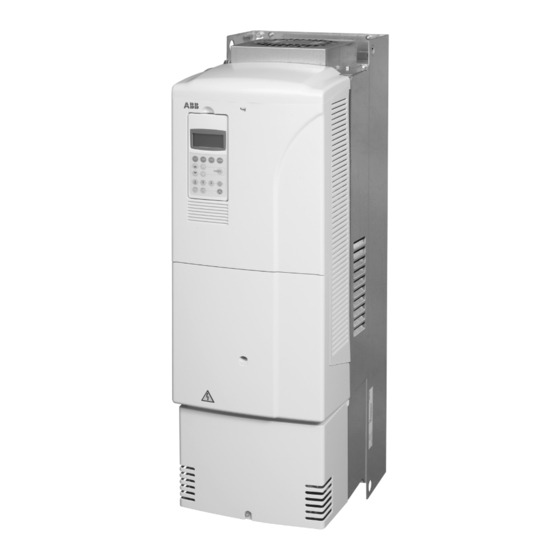
24 Operation principle and hardware description Product overview The ACS800-31/U31 is wall mountable, low-harmonic drive for controlling AC motors. IP21 (UL type 1) IP20 (UL type open) Cooling fan Top cover Control panel CDP 312R Heat sink Front cover Clear plastic... - Page 25 Operation principle and hardware description 25 Motor-side converter RMIO board I/O terminals Line-side converter RMIO board U1 V1 U2 V2 W2 Power cable terminals Frame size R5 without front and connection box covers...
- Page 26 26 Operation principle and hardware description Line-side converter RMIO board Motor-side converter RMIO board I/O terminals Power cable terminals Frame size R6 without front and connection box covers...
-
Page 27: Terms
Operation principle and hardware description 27 Terms Line-side converter: A converter that is connected to the supply network and is capable of transferring energy from the network to the DC link. Motor-side converter: A converter that is connected to the motor and controls the motor operation. -
Page 28: Ac Voltage And Current Waveforms
28 Operation principle and hardware description AC voltage and current waveforms The AC line current of the drive is sinusoidal with power factor equal to 1. The IGBT supply unit does not generate characteristic current or voltage overtones like a traditional 6- or 12-pulse bridge does. -
Page 29: Printed Circuit Boards
Operation principle and hardware description 29 Printed circuit boards The drive has the following printed circuit boards as standard: • Main circuit board (GINT) • Motor control and I/O board (RMIO), 2 pcs • EMC filter unit (GRFCU) when EMC equipment is selected •... -
Page 30: Main Circuit And Control Interfaces Diagram
30 Operation principle and hardware description Main circuit and control interfaces diagram... -
Page 31: Fieldbus Control Of The Line-Side Converter
Operation principle and hardware description 31 Fieldbus control of the line-side converter Optional fieldbus modules cannot be inserted in the optional module slots of the RMIO board of the line-side converter. Fieldbus control of the line-side converter is done via the motor-side converter RMIO board as shown in the block diagram below. Control block diagram The figure below shows the parameters for DC and reactive power reference selection of the line-side converter control program. -
Page 32: Connection Diagram Of The Rmio Board In The Line-Side Converter
32 Operation principle and hardware description Connection diagram of the RMIO board in the line-side converter Internal connections to the RMIO board for the ACS800 IGBT Supply Control Program are shown below. Do not change the connections. Terminal block size: VREF- Reference voltage -10 VDC, 1 kohm <... -
Page 33: Type Code
The type code has information on the specifications and configuration of the drive. The first digits from left express the basic configuration (for example, ACS800-31-0025-3 or ACS800-U31-0025-3). The optional selections are given thereafter, separated by plus signs (for example, +E200 and +K454). The main selections are described below. - Page 34 34 Operation principle and hardware description...
-
Page 35: Mechanical Installation
Mechanical installation 35 Mechanical installation What this chapter contains This chapter contains unpacking instructions, the delivery checklist and the mechanical installation instructions of the drive. Unpacking the unit The drive is delivered in a box that contains: • Plastic accessory bag: screws (M3), clamps and cable lugs (2 mm , M3) for grounding the control cable screens •... -
Page 36: Checking The Delivery
36 Mechanical installation To unpack the package, cut the bands (A) and remove the outer box (B) and sleeve (C). 3AUA0000075717 Checking the delivery Unpacking the unit Check that all items listed in (page 35) are present. Check that there are no signs of damage. Before attempting installation and operation, check the information on the type designation label of the drive to verify that the unit is of the correct type. -
Page 37: Moving The Unit
Mechanical installation 37 The type designation label is attached to the heat sink and the serial number label to the lower part of the back plate of the unit. Example labels are shown below. Type designation label Serial number label Moving the unit Lift the unit using the lifting holes at the top and bottom. -
Page 38: Before Installation
38 Mechanical installation Before installation The drive must be installed in an upright position with the cooling section facing a wall. Check the installation site according to the requirements below. Refer to Dimensional drawings (page 137) for frame details. WARNING! Do not remove the protective film that covers the unit before the installation procedure is complete. -
Page 39: Free Space Around The Unit
Mechanical installation 39 Free space around the unit Required free space around the drive to enable cooling air flow, service and maintenance is shown below in millimeters and [inches]. 200 [7.9] 50 [2.0] 50 [2.0] 200 [7.9] IP21 (UL 1) Cooling air flow Mounting the drive on the wall Units without vibration dampers... -
Page 40: Cabinet Installation
40 Mechanical installation Note that the kit has only four vibration dampers, but units of frame size R6 require six. Two dampers are installed in the middle. Cabinet installation The drive can be installed in a cabinet without the plastic front, top and connection box covers and without the lead-through plate. -
Page 41: Unit Above Another
Mechanical installation 41 Unit above another Lead the out-coming hot cooling air away from the air input of the drive above. max.+40 °C (+104 °F) Installing cabinet duct plates (optional) If the drive is installed in a cabinet that is inside a cooling air duct, duct plates can be used to lead the air flow. -
Page 42: Before You Start
42 Mechanical installation Screws are not included in the installation kit. The following screws are needed: • Frame size R5: 18 pieces: M5X12, torque 3 N·m (2.2 lbf·ft) 2 pieces: M4X16, torque 1.2 N·m (0.9 lbf·ft) 2 pieces: M4X12, torque 1.2 N·m (0.9 lbf·ft) •... -
Page 43: Assembly Drawing For Cabinet Duct Plates
Mechanical installation 43 Assembly drawing for cabinet duct plates... - Page 44 44 Mechanical installation...
-
Page 45: Planning The Electrical Installation
Note: The installation must always be designed and made according to applicable local laws and regulations. ABB does not assume any liability whatsoever for any installation which breaches the local laws and/or other regulations. Furthermore, if the recommendations given by ABB are not followed, the drive may experience problems that the warranty does not cover. -
Page 46: Motor Selection And Compatibility
… and … … then the motor voltage rating should be … IGBT supply DC link voltage is not increased from ACS800-31/U31 nominal (parameter setting) DC link voltage is increased from ACeq2 nominal (parameter setting) = Rated input voltage of the drive /1.41... - Page 47 The stress on motor insulation can be avoided by using optional ABB d filters. filters also reduce bearing currents.
-
Page 48: Requirements Table
Motor Nominal mains Requirement for type voltage (AC line Motor insulation ABB d filter, insulated N-end bearing and ABB voltage) system common mode filter < 100 kW 100 kW < < > 350 kW 350 kW or frame size >... - Page 49 Planning the electrical installation 49 Motor Nominal mains Requirement for type voltage (AC line Motor insulation ABB d filter, insulated N-end bearing and ABB voltage) system common mode filter < 100 kW 100 kW < < > 350 kW 350 kW or frame size >...
- Page 50 Note 3: The rated output power of high output motors is higher than what is stated for the particular frame size in EN 50347:2001. This table shows the requirements for ABB random-wound motor series (for example, M3AA, M3AP and M3BP).
- Page 51 All AMA machines (manufactured in Helsinki) for drive systems have form-wound windings. All HXR machines manufactured in Helsinki starting 1.1.1998 have form- wound windings. ABB motors of types other than M2_, M3_, HX_ and AM_ Note 6: Use the selection criteria given for non-ABB motors.
- Page 52 52 Planning the electrical installation Resistor braking of the drive Note 7: When the drive is in braking mode for a large part of its operation time, the intermediate circuit DC voltage of the drive increases, the effect being similar to increasing the supply voltage by up to 20 percent.
-
Page 53: Permanent Magnet Motor
Planning the electrical installation 53 Permanent magnet motor Only one permanent magnet motor can be connected to the drive output. It is recommended to install a safety switch between the permanent magnet motor and the drive output. The switch is needed to isolate the motor during any maintenance work on the drive. -
Page 54: Sensors
The drive protects the motor cable and motor in a short-circuit situation when: • the motor cable is sized correctly • the motor cable type complies with the motor cable selection guidelines by ABB • the cable length does not exceed the allowed maximum length specified for the drive •... -
Page 55: Short-Circuit Protection
Protect the input cable and drive against short circuit according to the following guide lines. Circuit diagram Drive type Short-circuit protection DRIVE DOES NOT HAVE INPUT FUSES ACS800-31 Protect the drive and input Distribution Drive or drive ACS800-U31 cable with... -
Page 56: Ground Fault Protection
56 Planning the electrical installation Ground fault protection The drive has an internal ground fault protective function to protect the unit against ground faults in the motor and motor cable. This is not a personal safety or a fire protection feature. The ground fault protective function can be disabled with a ACS800 Firmware Manual parameter, refer to the appropriate The EMC filter of the drive has capacitors between the main circuit and the frame. -
Page 57: Prevention Of Unexpected Start-Up (Option +Q950)
Planning the electrical installation 57 Prevention of unexpected start-up (option +Q950) The drive can have an optional Prevention of unexpected start-up function according to standards: • IEC/EN 60204-1:1997 • ISO/DIS 14118:2000 • EN 1037:1996 • EN ISO 12100:2003 • EN 954-1:1996 •... -
Page 58: Safe Torque Off (Option +Q967)
58 Planning the electrical installation Safe torque off (option +Q967) The drive supports the Safe torque off (STO) function according to standards: • EN 61800-5-2:2007 • EN ISO 13849-1:2008 • IEC 61508 • IEC 61511:2004 • EN 62061:2005 The function also corresponds to Prevention of unexpected start-up of EN 1037. The STO may be used where power removal is required to prevent an unexpected start-up. -
Page 59: Safe Torque Off Circuit Diagram
Planning the electrical installation 59 Safe torque off circuit diagram ... -
Page 60: Selecting The Power Cables
Longer cables cause a motor voltage decrease which limits the available motor power. The decrease depends on the motor cable length and characteristics. Contact ABB for more information. Note that a sine filter (optional) at the drive output also causes a voltage decrease. -
Page 61: Alternative Power Cable Types
Planning the electrical installation 61 Alternative power cable types Power cable types that can be used with the drive are represented below. Recommended A separate PE conductor is required if the conductivity of the cable shield Symmetrical shielded cable: three phase conductors is <... -
Page 62: Additional Us Requirements
62 Planning the electrical installation Additional US requirements Type MC continuous corrugated aluminum armor cable with symmetrical grounds or shielded power cable must be used for the motor cables if metallic conduit is not used. For the North American market, 600 V AC cable is accepted for up to 500 V AC. 1000 V AC cable is required above 500 V AC (below 600 V AC). -
Page 63: Power Factor Compensation Capacitors
Planning the electrical installation 63 Power factor compensation capacitors Power factor compensation is not needed with AC drives. However, if a drive is to be connected in a system with compensation capacitors installed, note the following restrictions. WARNING! Do not connect power factor compensation capacitors to the motor cables (between the drive and the motor). -
Page 64: Using A Contactor Between The Drive And The Motor
64 Planning the electrical installation Using a contactor between the drive and the motor Implementing the control of the output contactor depends on how you select the drive to operate. When you have selected to use DTC motor control mode, and motor ramp stop, open the contactor as follows: Give a stop command to the drive. -
Page 65: Tive Loads
Planning the electrical installation 65 Protecting the relay output contacts and attenuating disturbances in case of inductive loads Inductive loads (relays, contactors, motors) cause voltage transients when switched off. The relay contacts on the RMIO board are protected with varistors (250 V) against overvoltage peaks. -
Page 66: Selecting The Control Cables
Germany) was tested and approved by ABB. Control panel cable In remote use, the cable connecting the control panel to the drive must not exceed 3 m (10 ft). The cable type tested and approved by ABB is used in control panel option kits. -
Page 67: Connection Of A Motor Temperature Sensor To The Drive I/O
Planning the electrical installation 67 Connection of a motor temperature sensor to the drive WARNING! IEC 61800-5-1 requires double or reinforced insulation between live parts when: • the accessible parts are non-conductive, or • the accessible parts are conductive, but not connected to the protective earth. -
Page 68: Control Cable Ducts
68 Planning the electrical installation The cable trays must have good electrical bonding to each other and to the grounding electrodes. Aluminum tray systems can be used to improve local equalizing of potential. A diagram of the cable routing is shown below. Motor cable Drive min 300 mm (12 in.) -
Page 69: Electrical Installation
Electrical installation 69 Electrical installation What this chapter contains This chapter describes the electrical installation procedure of the drive. WARNING! The work described in this chapter may only be carried out by a Safety instructions qualified electrician. Obey the (page 11) in this manual. Ignoring the safety instructions can cause injury or death. -
Page 70: Motor And Motor Cable
2. Measure the insulation resistance between each phase conductor and the Protective Earth conductor using a measuring voltage of 1000 V DC. The insulation resistance of an ABB motor must exceed 100 Mohm (reference value at 25 °C or 77 °F). For the insulation resistance of other motors, please consult the manufacturer’s instructions. -
Page 71: Units Of Frame Size R6
Electrical installation 71 Note: When the capacitors of EMC filter +E202 or +E200 are disconnected, the EMC CE marking Directive requirements in the second environment are not fulfilled. See (page 132). Units of frame size R6 Remove the two screws shown below. Note: Depending on the EMC filter type and the nominal voltage of the drive, there may be only one screw. -
Page 72: Connecting The Power Cables
72 Electrical installation Connecting the power cables Diagram Drive OUTPUT INPUT UDC+ UDC V1 W1 V2 W2 (PE) (PE) For alternatives, see Disconnecting device (disconnecting Motor means) (page 53). 1), 2) Grounding of the motor cable shield at the motor end If shielded cable is used (not required but recommended), use a separate PE cable (1) or a... -
Page 73: Conductor Stripping Lengths
Electrical installation 73 Conductor stripping lengths Strip the conductor ends as follows to fit them inside the power cable connection terminals. Frame size Stripping length 0.63 1.10 Allowed wire sizes, tightening torques Cable entries (page 124). Wall installed units (European version) ... - Page 74 74 Electrical installation Views of frame size R5 UDC+ UDC-...
- Page 75 Electrical installation 75 Frame sizes R6: Cable lug installation [16 to 70 mm (6 to 2/0 AWG) cables] Remove the screw terminals. Fasten the cable lugs to the remaining bolts with M10 nuts. Isolate the ends of the cable lugs with insulating tape or shrink tubing.
-
Page 76: Wall Installed Units (Us Version)
76 Electrical installation Wall installed units (US version) Remove the connection box cover. 2. Remove the front cover by releasing the retaining clip with a screw driver and lifting the cover from the bottom outwards. 3. Remove the gland plate by undoing the fastening screws. 4. -
Page 77: Warning Sticker
Electrical installation 77 Wire size Compression lug Crimping tool kcmil/AWG Manufacturer Type Manufacturer Type No. of crimps Burndy YA4C-L4BOX Burndy MY29-3 Ilsco CCL-4-38 Ilsco MT-25 Burndy YA2C-L4BOX Burndy MY29-3 Ilsco CRC-2 Ilsco IDT-12 Ilsco CCL-2-38 Ilsco MT-25 Burndy YA1C-L4BOX Burndy MY29-3 Ilsco CRA-1-38... -
Page 78: Connecting The Control Cables
78 Electrical installation Connecting the control cables Lead the cable through the control cable entry (1). Connect the control cables as described below. Connect the conductors to the Motor control and I/O appropriate detachable terminals of the RMIO board [refer to board (RMIO) (page 91)]. -
Page 79: 360-Degree Grounding
Electrical installation 79 360-degree grounding Insulation Double-shielded cable Single-shielded cable When the outer surface of the shield is covered with non-conductive material: Strip the cable carefully (do not cut the grounding wire and the shield) 2. Turn the shield inside out to expose the conductive surface. 3. -
Page 80: Cabling Of I/O And Fieldbus Modules
80 Electrical installation Cabling of I/O and fieldbus modules Module As short as possible Shield Note: The RDIO module does not include a terminal for cable shield grounding. Ground the pair cable shields here. Pulse encoder module cabling Note 1: If the encoder is of unisolated type, ground the encoder cable at the drive end only. -
Page 81: Attaching The Control Cables And Covers
Electrical installation 81 Attaching the control cables and covers When all control cables are connected, attach them together with cable ties. Units with a connection box: Attach the cables to the entry plate with cable ties. Units with a gland box: Tighten the clamping nuts of the cable glands. Attach the connection box cover. -
Page 82: Connecting A Pc To The Motor-Side Rmio Board
82 Electrical installation In the example below, one AIMA-01 I/O module adapter is connected to the RMIO boards of the line-side and motor-side converters. RMIO board of RMIO board of the line-side the motor-side converter *) converter RDCO RDCO AIMA-01 I/O module adapter *) WARNING! In frame size R6, you must remove the top cover to reach the RMIO board. -
Page 83: Installation Of The Agps Board (Prevention Of Unexpected Start-Up, +Q950)
Installation of the AGPS board (Prevention of unexpected start-up, +Q950) 83 Installation of the AGPS board (Prevention of unexpected start-up, +Q950) What this chapter contains This chapter describes the electrical installation of the optional Prevention of unexpected start-up function (+Q950) of the drive, and gives instructions for starting-up, validating and using the function. - Page 84 84 Installation of the AGPS board (Prevention of unexpected start-up, +Q950) WARNING! The supply voltage for the AGPS board is 115...230 V AC. If the board is supplied with 24 V DC, the board is damaged and it needs to be replaced.
-
Page 85: Circuit Diagram
Installation of the AGPS board (Prevention of unexpected start-up, +Q950) 85 115...230 V Circuit diagram This circuit diagram shows how the AGPS-11 kit is installed. Drive 115/230 VAC 3AFE00374994... -
Page 86: Start-Up And Validation
86 Installation of the AGPS board (Prevention of unexpected start-up, +Q950) Start-up and validation Action Safety instructions Obey the safety instructions. See on page 11. Make sure that the drive can be run and stopped freely during the start-up. Stop the drive (if running), switch the input power off and isolate the drive from the power line by a disconnector. -
Page 87: Installation Of The Asto Board (Safe Torque Off, +Q967)
Installation of the ASTO board (Safe torque off, +Q967) 87 Installation of the ASTO board (Safe torque off, +Q967) What this chapter contains This chapter describes the electrical installation of the optional Safe torque off function (+Q967) of the drive and the specifications of the board. Safe torque off (+Q967) The optional Safe torque off function includes an ASTO board, which is connected to the drive and an external power supply. - Page 88 88 Installation of the ASTO board (Safe torque off, +Q967) WARNING! The supply voltage for the ASTO-11C board is 24 V DC. If the board is supplied with 230 V AC, the board is damaged and it needs to be replaced.
-
Page 89: Circuit Diagram
Installation of the ASTO board (Safe torque off, +Q967) 89 Circuit diagram The diagram below shows the connection between the ASTO board and the drive when it is ready. For an example diagram of a complete Safe torque off circuit, see page 59. - Page 90 90 Installation of the ASTO board (Safe torque off, +Q967)
-
Page 91: Motor Control And I/O Board (Rmio)
Motor control and I/O board (RMIO) 91 Motor control and I/O board (RMIO) What this chapter contains This chapter shows • external control connections to the RMIO board for the ACS800 Standard Control Program (Factory Macro) • specifications of the inputs and outputs of the board. Note on terminal labelling Optional modules (Rxxx) may have identical terminal designations with the RMIO board. -
Page 92: Parameter Settings
92 Motor control and I/O board (RMIO) The RMIO board can be supplied from an external power source via terminal X23 or X34 or via both X23 and X34. The internal power supply to terminal X34 can be left connected when using terminal X23. Parameter settings ... -
Page 93: External Control Connections (Non-Us)
Motor control and I/O board (RMIO) 93 External control connections (non-US) External control cable connections to the RMIO board for the ACS800 Standard Control Program (Factory Macro) are shown below. For external control connections Firmware Manual of other application macros and programs, see the appropriate RMIO RMIO Terminal block size:... -
Page 94: External Control Connections (Us)
94 Motor control and I/O board (RMIO) External control connections (US) External control cable connections to the RMIO board for the ACS800 Standard Control Program (Factory Macro US version) are shown below. For external control connections of other application macros and programs, see the appropriate Firmware Manual RMIO RMIO... -
Page 95: Rmio Board Specifications
Motor control and I/O board (RMIO) 95 RMIO board specifications Analogue inputs Two programmable differential current inputs (0 mA / 4 mA ... 20 mA, = 100 ohm) and one programmable differential voltage input (-10 V / 0 V / 2 V ... +10 V, >... -
Page 96: Relay Outputs
Isolation test voltage 4 kV AC, 1 minute DDCS fiber-optic link With optional communication adapter module RDCO. Protocol: DDCS (ABB Distributed Drives Communication System) 24 VDC power input Voltage 24 V DC ± 10% Typical current 250 mA... - Page 97 Motor control and I/O board (RMIO) 97 Isolation and grounding diagram (Test voltage: 500 V AC) VREF- AGND VREF+ AGND AI1+ Common mode AI1- voltage between AI2+ channels ±15 V AI2- AI3+ AI3- AO1+ AO1- AO2+ AO2- Jumper J1 settings: DGND1 All digital inputs share a common ground.
- Page 98 98 Motor control and I/O board (RMIO)
-
Page 99: Installation Checklist
Installation checklist 99 Installation checklist What this chapter contains This chapter contains an installation checklist. Installation checklist Check the mechanical and electrical installation of the drive before start-up. Go through the checklist below together with another person. WARNING! Only qualified electricians are allowed to commission the drive. Safety instructions Read and obey the (page 119) in this manual. - Page 100 100 Installation checklist Check that... ELECTRICAL INSTALLATION Planning the electrical installation Electrical installation (page 45), (page 69). The +E202 and +E200 EMC filter capacitors are disconnected if the drive is connected to an IT (ungrounded) system. IT (ungrounded) systems (page 70). Converter The capacitors are reformed if stored over one year, refer to modules with electrolytic DC capacitors in the DC link, Capacitor reforming...
- Page 101 Installation checklist 101 Check that... The motor connections at U2, V2 and W2 and their tightening torques are OK. The motor cable is routed away from other cables. There are no power factor compensation capacitors in the motor cable. The external control connections inside the drive are OK. There are no tools, foreign objects or dust from drilling inside the drive.
- Page 102 102 Installation checklist Check that... The motor connections at U2, V2 and W2 and their tightening torques are OK. The motor cable is routed away from other cables. There are no power factor compensation capacitors in the motor cable. The external control connections inside the drive are OK. There are no tools, foreign objects or dust from drilling inside the drive.
-
Page 103: Start-Up And Use
Start-up and use 103 Start-up and use What this chapter contains This chapter describes the start-up procedure and use of the drive, and the control panel control of the line-side and motor-side converters. Start-up and use WARNING! Only qualified electricians are allowed to commission the drive. Safety instructions Read and obey the (page 11) in this manual. -
Page 104: Control Panel
104 Start-up and use the line-side converter (ID number 2), the drive does not stop by pressing the control panel Stop key in local control mode. Have the control panel control the RMIO board of the motor-side converter in normal use. •... -
Page 105: To Control The Line-Side Converter
Start-up and use 105 To control the line-side converter... Step Action Push key Display (example) Enter the Drive Selection Mode. Note: In local control mode, the motor-side ACS 800 0050_5MR converter trips if parameter 30.02 PANEL LOSS is DRIVE ASXR7xxx set to FAULT. -
Page 106: To Control The Motor-Side Converter
106 Start-up and use To control the motor-side converter... Step Action Push key Display (example) Enter the Drive Selection Mode. ACS 800 0050_5LR DRIVE IXXR7xxx ID-NUMBER 2 Scroll to ID number 1. ACS 800 0050_5MR ACXR7xxx ID-NUMBER 1 Verify the change to the motor-side converter. ->... -
Page 107: Actual Signals And Parameters
Actual signals and parameters 107 Actual signals and parameters What this chapter contains This chapter contains listings of parameters specific to the ACS800-31 and ACS800-U31. Line-side converter actual signals and parameters in the motor-side converter control program This section describes the actual signals and parameters of the line-side converter control program which are copied to the motor-side converter control program. -
Page 108: Actual Signals
108 Actual signals and parameters Actual signals Name/Value Description FbEq Def. 09 ACTUAL SIGNALS Signals from the line converter. LCU ACT SIGNAL 1 Line converter signal selected by par. 95.08 LCU PAR1 1 = 1 09.12 SEL. LCU ACT SIGNAL 2 Line converter signal selected by par. -
Page 109: Acs800-31/U31 Specific Parameters In The Igbt Supply Control Program
Control Program The signals and parameters of the IGBT Supply Control Program which are specific to the ACS800-31 and ACS800-U31 are described in the tables below. These parameters need not be set in a normal start-up. For more information on... -
Page 110: 31 Automatic Reset
110 Actual signals and parameters Name/Value Description T./FbE Def. 31 AUTOMATIC RESET Automatic fault reset. Automatic resets are possible only for certain fault types and when the automatic reset function is activated for that fault type. The automatic reset function is not operational if the drive is in local control (L visible on the first row of the control panel display). -
Page 111: Fixed Parameters With The Acs800-31 And Acs800-U31
Actual signals and parameters 111 Fixed parameters with the ACS800-31 and ACS800-U31 When the IGBT Supply Control Program is loaded into the ACS800-31 or ACS800-U31, the following parameters are set to the default values given in the table below. - Page 112 112 Actual signals and parameters...
-
Page 113: Maintenance
Ignoring the safety instructions can cause injury or death. Maintenance intervals If installed in an appropriate environment, the drive requires very little maintenance. This table lists the routine maintenance intervals recommended by ABB. Interval Maintenance Instruction... -
Page 114: Heatsink
114 Maintenance Consult your local ABB Service representative for more details on the maintenance. On the Internet, go to http://www.abb.com/drivesservices. Heatsink The heatsink fins pick up dust from the cooling air. The drive runs into overtemperature warnings and faults if the heatsink is not clean. In a “normal”... -
Page 115: Fan Replacement (R5, R6)
Maintenance 115 Fan replacement (R5, R6) Loosen the fastening screws of the top plate. 2. Push the top plate backwards. 3. Lift the top plate up. 4. Disconnect the fan supply wires (detachable connector). 5. Lift the fan up. 6. -
Page 116: Capacitors
It is not possible to predict a capacitor failure. Capacitor failure is usually followed by a mains fuse failure or a fault trip. Contact ABB if capacitor failure is suspected. Replacements are available from ABB. Do not use other than ABB specified spare parts. -
Page 117: Fault Tracing
Fault tracing 117 Fault tracing What this chapter contains This chapter describes the fault and warning messages displayed on the control panel and the LEDs of the drive. For a detailed description of the fault and warning messages, see the appropriate firmware manual. Faults and warnings displayed by the CDP 312R control panel The control panel displays the Warning and Fault messages of the unit (that is, line-... -
Page 118: Conflicting Id Numbers
118 Fault tracing The warnings and faults concerning the motor-side converter are described in the Firmware Manual control program (for example, Standard Control Program) Conflicting ID numbers If the ID numbers of the line-side and the motor-side converters are set equal, the control panel stops functioning. -
Page 119: Technical Data
CE and other markings and warranty policy. IEC data Ratings The IEC ratings for the ACS800-31 with 50 Hz and 60 Hz supplies are given below. The symbols are described below the table. ACS800-31 Nominal Light-overload... -
Page 120: Symbols
120 Technical data ACS800-31 Nominal Light-overload Heavy-duty use Frame Air flow Heat dis- overload type ratings size sipation cont.max cont.max -0060-3 1750 -0070-3 2350 -0100-3 2800 Three-phase supply voltage 380 V, 400 V, 415 V, 440 V, 460 V, 480 V or 500 V -0020-5 18.5... -
Page 121: Derating
Technical data 121 Derating The load capacity (current and power) decreases if the installation site altitude exceeds 1000 m (3300 ft), or if the ambient temperature exceeds 40 °C (104 °F). Temperature derating In the temperature range +40 °C (+104 °F) to +50 °C (+122 °F) the rated output current is decreased 1% for every additional 1 °C (1.8 °F). -
Page 122: Mains Cable Fuses
Note 1: In multi-cable installations, install only one fuse per phase (not one fuse per conductor). Note 2: Larger fuses must not be used. Note 3: Fuses from other manufacturers can be used if they meet the ratings. gG fuses ACS800-31 type Input Fuse current... - Page 123 Technical data 123 aR fuses ACS800-31 type Input Fuse current Manufacturer Fuse Type DIN 43620 (@660V) size Three-phase supply voltage 208 V, 220 V, 230 V or 240 V -0011-2 1450 Bussmann 170M1565 -0016-2 2550 Bussmann 170M1566 -0020-2 4650 Bussmann...
-
Page 124: Cable Types
124 Technical data Cable types The table below gives copper and aluminum cable types for different load currents. Cable sizing is based on max. 9 cables laid on a cable ladder side by side, ambient temperature 30 °C (86 °F), PVC insulation, surface temperature 70 °C (158 °F) (EN 60204-1 and IEC 60364-5-2:2001). -
Page 125: Nema Data
Technical data 125 NEMA data Ratings The NEMA ratings for the ACS800-U31 and ACS800-31 with 60 Hz supplies are given below. The symbols are described below the table. For sizing, derating and 50 Hz IEC data supplies, see (page 119). -
Page 126: Input Cable Fuses
Note 2: Larger fuses must not be used. Note 3: Fuses from other manufacturers can be used if they meet the ratings. ACS800-U31 type Input Fuse current ACS800-31 type Manufacturer Type UL class Three-phase supply voltage 208 V, 220 V, 230 V or 240 V -0011-2... -
Page 127: Cable Types
Technical data 127 Cable types Cable sizing is based on NEC Table 310-16 for copper wires, 75 °C (167 °F) wire insulation at 40 °C (104 °F) ambient temperature. Not more than three current- carrying conductors in raceway or cable or earth (directly buried). For other conditions, dimension the cables according to local safety regulations, appropriate input voltage and the load current of the drive. -
Page 128: Input Power Connection
128 Technical data Input power connection Voltage ( 208/220/230/240 V AC 3-phase ± 10% for 230 V AC units 380/400/415 V AC 3-phase ± 10% for 400 V AC units 380/400/415/440/460/480/500 V AC 3-phase ± 10% for 500 V AC units 525/550/575/600/660/690 V AC 3-phase ±... -
Page 129: Motor Connection
Technical data 129 Motor connection Voltage ( 0 to , 3-phase symmetrical, at the field weakening point Frequency DTC mode: 0 to 3.2 · . Maximum frequency 300 Hz. Nmains · f Nmotor Nmotor : frequency at field weakening point : mains (input power) voltage Nmains : rated motor voltage... -
Page 130: Asto-11C (Option +Q967)
130 Technical data ASTO-11C (option +Q967) Supply voltage range +24 V DC +/- 10% Current consumption 40 mA (20 mA per channel) Supply cable A single-shielded twisted pair Maximum cable length 300 m Conductor min. cross 0.5 mm , 20 AWG section X1 terminal sizes 4 x 2.5 mm... -
Page 131: Materials
EU. They must be removed and handled according to local regulations. For further information on environmental aspects and more detailed recycling instructions, please contact your local ABB distributor. Applicable standards The drive complies with the following standards. -
Page 132: Ce Marking
132 Technical data CE marking A CE mark is attached to the drive to verify that the unit follows the provisions of the European Low Voltage and EMC Directives. The CE marking also verifies that the drive, in regard to its safety functions (such as Safe torque off), conforms with the Machinery Directive as a safety component. -
Page 133: First Environment (Drive Of Category C2)
Technical data 133 First environment (drive of category C2) The drive complies with the standard with the following provisions: The drive has EMC filter +E202. Hardware Manual 2. The motor and control cables are selected as specified in the Hardware Manual 3. -
Page 134: Second Environment (Drive Of Category C4)
Equipment Equipment 2. An EMC plan for preventing disturbances is drawn up for the installation. A template is available from the local ABB representative. Hardware Manual 3. The motor and control cables are selected as specified in the Hardware Manual 4. -
Page 135: Ul/Csa Markings
Technical data 135 UL/CSA markings The ACS800-U31 and ACS800-31 drives of UL type 1 are cULus listed and cCSAus certified. UL checklist • The drive is to be used in a heated, indoor controlled environment. The drive must be installed in clean air according to enclosure classification. Cooling air must be clean, free from corrosive materials and electrically conductive dust. - Page 136 136 Technical data...
-
Page 137: Dimensional Drawings
Dimensional drawings 137 Dimensional drawings The dimensions are given in millimeters and [inches]. -
Page 138: Frame Size R5 (Ip21, Ul Type Open, Ul Type 1)
138 Dimensional drawings Frame size R5 (IP21, UL type open, UL type 1) -
Page 139: Frame Size R6 (Ip21, Ul Type Open, Ul Type 1)
Dimensional drawings 139 Frame size R6 (IP21, UL type open, UL type 1) -
Page 140: Cabinet Duct Plates (Optional), Frame Size R5
140 Dimensional drawings Cabinet duct plates (optional), frame size R5... -
Page 141: Cabinet Duct Plates (Optional), Frame Size R6
Dimensional drawings 141 Cabinet duct plates (optional), frame size R6... -
Page 142: Package (Frame Size R5)
142 Dimensional drawings Package (frame size R5) 1085 [42.72] 400 [15.75] Package (frame size R6) 1145 [45.08] 400 [15.75]... -
Page 143: Agps Board With Enclosure (Optional)
Dimensional drawings 143 AGPS board with enclosure (optional) 3AFE68293898... -
Page 144: Asto Board With Enclosure (Optional)
144 Dimensional drawings ASTO board with enclosure (optional) 3AUA0000068698... -
Page 145: Resistor Braking
Resistor braking 145 Resistor braking What this chapter contains This chapter describes how to select, protect and wire external brake choppers and resistors for the drive. The chapter also contains installation instructions and the technical data. How to select the correct drive/chopper/resistor combination NBRA-6xx Braking Choppers Installation and Start-up Guide Refer to... -
Page 146: External Brake Chopper And Resistor(S) For The Acs800-31/U31
146 Resistor braking External brake chopper and resistor(s) for the ACS800- 31/U31 The nominal ratings for dimensioning the brake resistors for the ACS800-31 and ACS800-U31 are given below at an ambient temperature of 40 °C (104 °F). ACS800-31 Chopper Brake resistor... -
Page 147: Brake Chopper And Resistor Installation
Below is a simple example wiring diagram. Fuses ACS800 V1 W1 Thermal switch (standard in ABB resistors) -
Page 148: Brake Circuit Commissioning
OFF2 STOP. For the use of the brake resistor overload protection (parameters 27.02...27.05), consult an ABB representative. WARNING! If the drive is equipped with a brake chopper but the chopper is not enabled by parameter setting, the brake resistor must be disconnected because the protection against resistor overheating is then not in use. -
Page 149: External +24 V Power Supply For The Rmio Boards Via Terminal X34
External +24 V power supply for the RMIO boards via terminal X34 149 External +24 V power supply for the RMIO boards via terminal What this chapter contains This chapter describes how to connect an external 24 V power supply for the RMIO boards of the motor-side and line-side converters via terminal X34. -
Page 150: Connecting 24 V External Power Supply
150 External +24 V power supply for the RMIO boards via terminal X34 Connecting 24 V external power supply RMIO board of the motor-side converter Use pliers to break off the tab that covers the +24 VDC power input connector. 2. - Page 151 External +24 V power supply for the RMIO boards via terminal X34 151 RMIO board Connection of a two-way connector RMIO board Connection of a three-way connector...
-
Page 152: Rmio Board Of The Line-Side Converter
152 External +24 V power supply for the RMIO boards via terminal X34 RMIO board of the line-side converter Frame size R5 The location of terminal X34 in the line-side converter is shown below. Connect the RMIO board of the external +24 V supply to the board as described in steps 2 to 8 in motor-side converter (page 150). -
Page 153: Frame Size R6
External +24 V power supply for the RMIO boards via terminal X34 153 Frame size R6 Remove the top cover by releasing the retaining clip with a screw driver and lifting the cover upwards. 2. Disconnect the DDCS communication module by undoing the fastening screws and disconnecting the fiber-optic cables. - Page 154 154 External +24 V power supply for the RMIO boards via terminal X34...
- Page 155 Product and service inquiries Address any inquiries about the product to your local ABB representative, quoting the type designation and serial number of the unit in question. A listing of ABB sales, support and service contacts can be found by navigating to abb.com/searchchannels...
- Page 156 © Copyright 2023 ABB. All rights reserved. Specifications subject to change without notice.