
Related Manuals for Toro eTimeCutter eMR4275


Summary of Contents for Toro eTimeCutter eMR4275
- Page 1 Operator’s Manual eTimeCutter® eMR4275 Zero Turn Riding Mower Model—Serial Range 75642—400000000 and Up *3445-793* A 3445-793A Original Instructions (EN)
-
Page 2: Table Of Contents
Hauling the Machine ........................4–19 Chapter 5: Maintenance ........................5–1 Maintenance Safety ......................... 5–1 Recommended Maintenance Schedule..................5–2 © 2023—The Toro ® Company Contact us at www.Toro.com 8111 Lyndale Ave So Printed in the USA Bloomington, MN 55044 All rights reserved... - Page 3 Pre-Maintenance Procedures ....................... 5–2 Moving a Non-Functioning Machine ..................5–2 Raising the Machine ........................5–3 Electrical System Maintenance..................... 5–4 Preparing the Battery Pack for Recycling................5–4 Checking the Battery-Box Filter ....................5–4 Drive System Maintenance ......................5–5 Checking the Tire Pressure......................5–5 Checking the Wheel Lug Nuts....................
-
Page 4: Chapter 1: Introduction
Whenever you need service, genuine Toro parts, or additional information, contact an Authorized Service Dealer or Toro Customer Service and have the model and serial numbers of your product ready. These numbers are located on the serial plate on your product . -
Page 5: Chapter 2: Safety
Chapter 2 Safety General Machine Safety Warnings WARNING—Read all safety warnings, instructions, illustrations and specifications provided with this machine. Failure to follow the warnings and instructions may result in electric shock, fire and/ or serious injury. The term “machine” in all of the warnings listed below refers to your mains-operated (corded) machine or battery-operated (cordless) machine. - Page 6 3. Personal safety A. Stay alert, watch what you are doing, and use common sense when operating the machine. Do not use the machine while you are tired or under the influence of drugs, alcohol, or medication. A moment of inattention while operating the machine may result in serious personal injury.
-
Page 7: Lawn Mower Safety Warnings
performed. Use of the machine for operations different from those intended could result in a hazardous situation. H. Keep handles and grasping surfaces dry, clean and free from oil and grease. Slippery handles and grasping surfaces do not allow for safe handling and control of the machine in unexpected situations. - Page 8 D. Before using the lawnmower, always visually inspect to see that the blade and the blade assembly are not worn or damaged. Worn or damaged parts increase the risk of injury. E. Keep guards in place. Guards must be in working order and be properly mounted. A guard that is loose, damaged, or is not functioning correctly may result in personal injury.
-
Page 9: Additional Safety Messages
Additional Safety Messages Safety-Alert Symbol The safety-alert symbol shown in this manual and on the machine identifies important safety messages that you must follow to prevent accidents. G405934 DANGER indicates an imminently hazardous situation which, if not avoided, will result in death or serious injury. -
Page 10: Slope Indicator
Slope Indicator You may copy this page for personal use. G011841s The maximum slope you can operate the machine on is 15 degrees. Use the slope chart to determine the degree of slope of hills before operating. Do not operate this machine on a slope greater than 15 degrees. Fold along the appropriate line to match the recommended slope. -
Page 11: Safety And Instructional Decals
Safety and Instructional Decals Safety decals and instructions are easily visible to the operator and are located near any area of potential danger. Replace any decal that is damaged or missing. Decal Part: 130-0731 Warning—thrown object hazard; keep the deflector in place. Cutting hazard of hand or foot, s_decal130-0731 mower blade—keep away from moving... - Page 12 Decal Part: 145-3802 s_decal145-3802 The battery pack is charging. The battery pack is over or under the appropriate temperature range. The battery pack is fully charged. Battery pack charging fault. The battery pack charging is on standby while other batteries charge (charging mode dependent).
- Page 13 Decal Part: 147-0290 Warning—light is bright; do not look directly into the light. decal147-0290 Decal Part: 147-7614 Blade control—fast Traction drive—fast Blade control—slow Traction drive—slow decal147-7614 Decal Part: 147-7615 Thrown object hazard—keep bystanders away. Thrown object hazard, mower—do not operate without the deflector, discharge cover, or grass collection system in place.
- Page 14 Decal Part: 147-7616 decal147-7616 Note: This machine complies with the industry standard stability test in the static lateral and longitudinal tests with the maximum recommended slope indicated on the decal. Review the instructions for operating the machine on slopes in the Operator’s Manual as well as the conditions in which you would operate the machine to determine whether you can operate the machine in the conditions on that day and at that site.
- Page 15 Decal Part: 147-7620 Fast Slow Neutral Reverse Traction controls decal147-7620 Decal Part: 147-7621 Read the Operator’s Manual. Full function Limited function No function/extremely limited function decal147-7621 3445-793A Page 2–11 Safety: Safety and Instructional Decals...
-
Page 16: Chapter 3: Product Overview
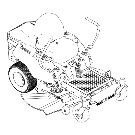
Chapter 3 Product Overview MyRide® suspension adjustment lever Battery box Motion-control lever Parking brake Caster wheel Anti-scalp roller Height-of-cut lever Grass deflector Control panel G427499 Battery charger Battery pack (4 included) G448680 Product Overview Page 3–1 3445-793 A... -
Page 17: Control Panel
Control Panel Become familiar with all the controls before you start and operate the machine. Blade-speed switch Traction-speed switch Information display Blade-control switch (power takeoff) Key switch G427498 Key Switch Use the key switch to power the machine O . Turn the key past the O position to start the machine. - Page 18 Blade-Speed Switch Use the blade-speed switch to select a faster or slower blade speed. Note: Use the F position for best cutting performance; use the S position for less energy consumption. G428591 Blade-Control (PTO) Switch The blade-control switch, represented by a power- takeoff (PTO) symbol, engages and disengages power to the mower blades.
- Page 19 Information Display (continued) Display Icon The battery temperature The operator is not in the is too high. seat. The blade-control switch The battery load is too (PTO) is engaged. high. The blade-control switch (PTO) is engaged but the machine is preventing the Limp mode is active.
-
Page 20: Parking Brake
Parking Brake Whenever you shut off the machine, engage the parking brake to prevent accidental movement of the machine. You can use the parking brake to stop the machine in emergency situations or when a machine fault disables the traction controls. G428514 Motion-Control Levers Use the motion-control levers to drive the machine forward, reverse, and turn either... -
Page 21: Specifications
Specifications Note: Specifications and design are subject to change without notice. Machine Cutting width 107 cm (42 inches) Width with deflector down 136 cm (53-1/2 inches) Width with deflector down 116 cm (45-1/2 inches) Length 185 cm (73 inches) Height 114 cm (45 inches) Weight 250 kg (552 lb) - Page 22 Compatible Battery Chargers Model 81802 81805 81801 Type 60V MAX Lithium-Ion 60V MAX Lithium-Ion 60V MAX Lithium-Ion Battery Charger Battery Rapid Charger Battery Charger Input 100 to 240 V AC 100 to 240V AC ~5.0A, 220 to 240V AC ~2.0A, ~2.0A, 50/60Hz 50/60Hz 50-60 Hz...
- Page 23 Attachments/Accessories A selection of Toro approved attachments and accessories is available for use with the machine to enhance and expand its capabilities. Contact your Authorized Service Dealer or authorized Toro distributor or go to www.Toro.com for a list of all approved attachments and accessories.
-
Page 24: Chapter 4: Operation
• This product generates an electromagnetic field. If you wear an implantable electronic medical device, consult your health care professional before using this product. • Use only accessories and attachments approved by Toro. • Do not carry passengers on the machine and keep bystanders and pets away from the machine during operation. -
Page 25: Installing The Battery Packs
Installing the Battery Packs Any Flex-Force Power System® battery can be used with the machine. Install at least 3 fully charged batteries, with 4 Ah or higher, for best mowing performance; 2 or fewer batteries, or batteries with lower amperage, may only provide enough power to drive the machine. -
Page 26: Safety-Interlock System
Safety-Interlock System The safety-interlock system is designed to prevent the machine from driving or engaging the blades unless the parking brake is disengaged: It also is designed to shut off the blades whenever you rise from the seat. WARNING If the safety-interlock switches are disconnected or damaged, the machine could operate unexpectedly, causing personal injury. -
Page 27: Positioning The Seat
Safety-Interlock System (continued) 6. Disengage the blade-control switch. 7. Ensure that the parking brake is engaged and slowly move the motion-control levers forward. The machine should not move, and the information display should show the following icon. G427902 8. Shut off the machine and remove the key. Positioning the Seat G451798 Adjusting the Motion-Control Lever Height... -
Page 28: Adjusting The Motion-Control Lever Tilt
Adjusting the Motion-Control Lever Tilt Adjust the motion-control levers forward or rearward for your comfort. 1. Loosen the upper bolt. 2. Loosen the lower bolt enough to pivot the control lever forward or rearward. 3. Tighten both bolts. 4. Repeat the adjustment for the other control lever. -
Page 29: Converting To Side Discharge
Converting to Side Discharge Install the fasteners into the same holes in the deck from where they were originally removed. This ensures that no holes remain open when operating the mower deck. WARNING Open holes in the machine expose you and others to thrown debris that can cause severe injury. - Page 30 Converting to Side Discharge (continued) G468164 Existing carriage bolt—5/16 x 3/4 inch New hex bolt—5/16 x 3/4 inch (2) Existing nut—5/16 inch (3) 7. Remove the 2 kicker baffles and install the fasteners into the open holes. G468337 Thread-forming bolt—5/16 x 3/4 inch (4) Kicker baffle (2) 8.
-
Page 31: During Operation
During Operation During Operation Safety • Before you start the machine, ensure that all drives are in neutral. • Keep away from holes, ruts, bumps, rocks, and other hidden hazards. Use care when approaching blind corners, shrubs, trees, tall grass or other objects that may hide obstacles or obscure vision. -
Page 32: Starting The Machine
During Operation Safety (continued) Safe Zone—use the machine here on slopes less than 15° or flat areas. Danger Zone—use a walk- behind mower and/or a hand trimmer on slopes greater than 15° and near drop-offs or water. Water W = Width of the machine Keep a safe distance (twice the width of the machine) between the machine and any hazard. -
Page 33: Shutting Off The Machine
Shutting Off the Machine CAUTION Children or bystanders may be injured if they move or attempt to operate the machine while it is unattended. Always remove the key and engage the parking brake when leaving the machine unattended. 1. Park the machine on a level surface. 2. -
Page 34: Driving The Machine
Driving the Machine CAUTION Positioning one lever too far in front of the other causes the machine to spin very rapidly. As a result, you may lose control of the machine, causing personal injury to you and damage to the machine. Slow down the machine before making sharp turns. - Page 35 Driving the Machine (continued) 2. Slowly push the motion-control levers forward or rearward. Move 1 lever farther than the other lever to turn. Note: The farther you move the motion- control levers, the faster the machine moves in that direction. 3.
-
Page 36: Operating The Mower Blade-Control Switch (Pto)
Operating the Mower Blade-Control Switch (PTO) DANGER The rotating blades under the mower deck are dangerous. Blade contact will cause serious injury or death. Do not put your hands or feet under the mower or mower deck when the blades are engaged. -
Page 37: Side Discharge
Side Discharge The hinged grass deflector disperses clippings to the side and down toward the turf. DANGER Without the grass deflector, discharge cover, or complete grass catcher assembly mounted in place, you and bystanders are exposed to blade contact and thrown debris. -
Page 38: Adjusting The Anti-Scalp Rollers
Adjusting the Anti-Scalp Rollers Whenever you change the height of cut, adjust the height of the anti-scalp rollers. 1. Park the machine on a level surface, disengage the blade-control switch (PTO), and engage the parking brake. 2. Shut off the machine, remove the key, and wait for all moving parts to stop before leaving the operating position. - Page 39 Operating Tips (continued) Mowing Frequency Grass grows at different rates at different times of the year. To maintain the same cutting height, mow more often in early spring. As the grass growth rate slows in mid summer, mow less frequently. If you cannot mow for an extended period, first mow at a high cutting height, then mow again 2 days later at a lower height setting.
-
Page 40: After Operation
After Operation After Operation Safety • Disengage the PTO whenever you are transporting or not using the machine. • Use full-width ramps for loading the machine into a trailer or truck. • Tie the machine down securely using straps, chains, cable, or ropes. Both front and rear straps should be directed down and outward from the machine. - Page 41 Charging the Battery Packs (continued) 2. Line up the cavity in the battery pack with the tongue on the charger. 3. Slide the battery pack into the charger until it is fully seated 4. Wait for the battery pack(s) to charge. Refer to the following table to interpret the LED indicator light on the battery charger.
-
Page 42: Hauling The Machine
Hauling the Machine Use a heavy-duty trailer or truck to haul the machine. Use a full-width ramp. Ensure that the trailer or truck has all the necessary brakes, lighting, and marking as required by law. Please carefully read all the safety instructions. Knowing this information could help you or bystanders avoid injury. - Page 43 Hauling the Machine (continued) Full-width ramp(s) in stowed position Side view of full-width ramp in loading position Not greater than 15 degrees Ramp is at least 4 times as long as the height of the trailer or truck bed to the ground H = height of the trailer or truck bed to the ground...
- Page 44 Hauling the Machine (continued) 4. Back the machine up the ramp. 5. Shut off the machine, remove the key, and engage the parking brake. G414592 6. Tie down the machine using straps, chains, cable, or ropes. Refer to local regulations for tie-down requirements.
-
Page 45: Chapter 5: Maintenance
Modifying the original machine, parts, and/or accessories may alter the warranty, controllability, and safety of the machine. Making unauthorized modifications to the original machine and/or not using genuine Toro parts could lead to serious injury or death. • Do not make unauthorized modifications to the machine, parts, and/or accessories. -
Page 46: Recommended Maintenance Schedule
Recommended Maintenance Schedule Maintenance Maintenance Procedure Service Interval After the first 50 Check the lug-nut torque. hours Check the safety-interlock system. Before each use or Inspect the blades. daily Inspect the grass deflector for damage. Clean grass and debris from the machine. After each use Check the tire pressure. -
Page 47: Raising The Machine
Raising the Machine Use jackstands to support the machine when you raise it. WARNING Supporting the machine on the transaxle or motor may damage them and cause the machine to fall, injuring you or bystanders. Do not use the transaxle or motor to lift or support the machine. G454948 3445-793A Page 5–3... -
Page 48: Electrical System Maintenance
Electrical System Maintenance Preparing the Battery Pack for Recycling IMPORTANT Upon removal, cover the terminals of the battery pack with heavy-duty adhesive tape. Do not attempt to destroy or disassemble the battery pack or remove any of its components. Lithium-ion battery packs labeled with the Call2Recycle seal can be recycled at any participating retailer or battery recycling facility in the Call2Recycle program (US and Canada only). -
Page 49: Drive System Maintenance
Drive System Maintenance Checking the Tire Pressure Maintain the air pressure in the front and rear tires as specified. Uneven tire pressure can cause an uneven cut. Check the pressure at the valve stem when the tires are cold to get the most accurate pressure reading. - Page 50 Adjusting the Tracking (continued) G447992 5. Lower the seat. 6. Start the machine and drive it forward across a flat, level surface with both motion- control levers fully forward to verify that the machine tracks straight. Repeat the procedure as needed. Maintenance: Drive System Maintenance Page 5–6 3445-793 A...
-
Page 51: Mower-Deck Maintenance
Mower-Deck Maintenance Blade Service To ensure a superior quality of cut, keep the blades sharp. For convenient sharpening and replacement, keep extra blades on hand. Replace the blades if they hit a solid object, or if the blade is out of balance or bent. Before Inspecting or Servicing the Blades 1. - Page 52 Blade Service (continued) Blade edge previous measured Opposite blade edge G447261 5. Measure from the tip of the blade to the level surface. Blade (in position for measuring) Level surface Measured distance between blade and the surface (B) G447260 6. If the difference between A and B is greater than 3 mm (1/8 inch), replace the blade. Note: If you replace the blade and the difference continues to exceed 3 mm (1/8 inch), the blade motor shaft could be bent.
- Page 53 WARNING Operating a machine after incorrectly installing the blade assembly and/or not using genuine Toro blade and blade hardware could allow a blade or blade component to be thrown out from under the deck, resulting in serious injury or death.
-
Page 54: Leveling The Mower Deck
Leveling the Mower Deck Ensure that the mower deck is level any time you install the mower deck or when you see an uneven cut on your lawn. Preparing to Level the Mower Deck 1. Park the machine on a level surface, disengage the blade-control switch (PTO), and engage the parking brake. - Page 55 Leveling the Mower Deck (continued) 3. Position 1 blade front-to-rear. 4. Measure at locations from a level surface to the cutting edge of the blade tips The front blade tip should be 1.6 to 7.9 mm (1/ 16 to 5/16 inch) lower than the rear blade tip. If the measurement is not correct, adjust the front-to-rear level.
- Page 56 Leveling the Mower Deck (continued) 4. Place 2 blocks, each having a thickness of 7.3 cm (2-7/8 inches), under each side of the rear edge of the cutting deck skirt. 5. Adjust the side-to-side level as necessary: A. Remove the hairpin cotter and washer from the left lower lift-arm pin. G448684 B.
- Page 57 Leveling the Mower Deck (continued) D. Repeat the adjustment for the other side of the machine. E. Check the side-to-side level and adjust it again until the measurements are correct. 6. Adjust the front-to-rear level as necessary: A. Rotate the adjustment nut in the front of the mower deck. To raise the front of the deck, tighten the adjustment nut;...
-
Page 58: Brake Maintenance
Brake Maintenance Testing the Parking Brake 1. Start the machine. 2. Slowly drive the machine forward on level ground and engage the parking brake while moving. 3. Verify that the machine stops moving and the parking brake icon appears on the information display, then move the levers to neutral. -
Page 59: Cleaning
Cleaning Cleaning Under the Mower Deck Clean the underside of the mower deck after each use to prevent grass buildup for improved mulch action and clipping dispersal. IMPORTANT Do not use water to clean the mower deck, otherwise you could damage the electric motors. -
Page 60: Chapter 6: Storage
Chapter 6 Storage Storing the Machine Store the machine, battery pack, and charger only in temperatures that are within the appropriate range; refer to Specifications, page 3–6. 1. Park the machine on a level surface, disengage the blade-control switch (PTO), and engage the parking brake. -
Page 61: Chapter 7: Troubleshooting
Chapter 7 Troubleshooting Machine Troubleshooting The machine vibrates abnormally Possible Cause Corrective Action The cutting blade(s) is/are bent or Install new cutting blade(s). unbalanced. The blade mounting bolt is loose. Tighten the blade mounting bolt. The blade spindle is bent. Contact an Authorized Service Dealer. -
Page 62: Battery And Charger Troubleshooting
Battery and Charger Troubleshooting The battery system loses charge quickly. Possible Cause Corrective Action The battery system is over or under the Move the machine to a location where it is appropriate temperature range. dry and the temperature is within the range indicated in Specifications. - Page 63 The LED indicator light on the battery charger is red. Possible Cause Corrective Action The battery charger and/or battery pack is Unplug the battery charger and move the over or under the appropriate temperature battery charger and battery pack to a range.
-
Page 64: Display Error And Fault Code Troubleshooting
Display Error and Fault Code Troubleshooting Before diagnosing an error, shut off the machine, remove the key, and remove the batteries. Error Icons Description Icon Corrective Action Shut off the machine, remove the battery, and The battery temperature is too wait for the battery to cool. - Page 65 System for Fault First 2 Digits of Code System Power management unit (PMU)—battery box Primary controller Left traction motor Right traction motor 83, 84, or 85 Blade motor Power Management Unit (PMU) Faults Last 2 Digits of Fault Description Corrective Action Code Restart the machine;...
- Page 66 Power Management Unit (PMU) Faults (continued) Last 2 Digits of Fault Description Corrective Action Code Remove and charge the battery. Install the battery. If issues persist, replace the battery or contact an Authorized Service Dealer. Ensure that the battery is installed properly.
- Page 67 Primary Controller Faults (continued) Code Fault Description Corrective Action A fault occurred in the right motion- Check for loose connections; if issues 80-XXX-08 control sensor. persist, contact an Authorized Service Dealer. There is no CAN signal for the blade Check for loose connections; if issues 80-XXX-10 controller (refer to the serial number to persist, contact an Authorized Service...
- Page 68 Traction/Blade Motor Controller Faults (continued) Code Fault Description Corrective Action 82-XXX-02 83-XXX-02 84-XXX-02 85-XXX-02 81-XXX-07 82-XXX-07 Clear any obstructions; if issues The motor rotor is locked. persist, contact an Authorized Service 83-XXX-07 Dealer. 84-XXX-07 85-XXX-07 81-XXX-10 82-XXX-10 The motor rotor operates too fast. Contact an Authorized Service Dealer.
- Page 69 Traction/Blade Motor Controller Faults (continued) Code Fault Description Corrective Action 84-XXX-19 85-XXX-19 81-XXX-20 82-XXX-20 There is a gate driver integrated circuit Contact an Authorized Service Dealer. 83-XXX-20 (IC) component error. 84-XXX-20 85-XXX-20 81-XXX-21 82-XXX-21 Check for loose connections; if issues The connector on the motor phase is persist, contact an Authorized Service 83-XXX-21...
- Page 70 Traction/Blade Motor Controller Faults (continued) Code Fault Description Corrective Action 81-XXX-28 82-XXX-28 There is a flash data validation error. Contact an Authorized Service Dealer. 83-XXX-28 84-XXX-28 85-XXX-28 81-XXX-29 82-XXX-29 There is an MCU non-maskable Contact an Authorized Service Dealer. 83-XXX-29 interrupt error.
-
Page 71: Chapter 8: Schematic: Electrical Diagram
Chapter 8 Schematic: Electrical Diagram G465696 3445-793 A Page 8–1 Schematic: Electrical Diagram...