
Related Manuals for D-Link DMS-1250 Series


Summary of Contents for D-Link DMS-1250 Series
- Page 1 Version 1.02 | 12/25/2023 Hardware Installation Guide Multi-G Ethernet Smart Managed Switch DMS-1250 Series...
- Page 2 Information in this document is subject to change without notice. Reproduction in any manner whatsoever, without the written permission of D-Link Corporation, is strictly forbidden. Trademarks used in this text: D-Link and the D-LINK logo are trademarks of D-Link Corporation; Microsoft and Windows are registered trademarks of Microsoft Corporation.
-
Page 3: Table Of Contents
DMS-1250 Series Multi-G Ethernet Smart Managed Switch Hardware Installation Guide Table of Contents Typographical Conventions ........................... iv Notes and Cautions ............................... iv Switch Description ..............................1 Package Contents ..............................1 Features .................................. 1 Front Panel Components ............................2 Ports .................................. 3 Reset Button .............................. -
Page 4: Typographical Conventions
DMS-1250 Series Multi-G Ethernet Smart Managed Switch Hardware Installation Guide Intended Readers The DMS-1250 Series Multi-G Ethernet Smart Managed Switch Hardware Installation Guide contains detailed information about the hardware specifications of the switches in this series. It also contains brief information on how to configure and manage a switch in this series. -
Page 5: Switch Description
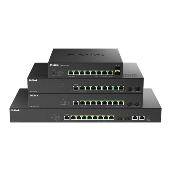
Side Panel Components Switch Description The DMS-1250 Series is D-Link’s next generation Smart Managed Switch. The Switch has a combination of 2.5GBASE-T and SFP+ ports that may be used to connect various networking devices to the Switch. The SFP+ ports are used with fiber-optical transceiver cabling in order to uplink various other networking devices for a 1Gbps or 10 Gbps link that may span great distances. -
Page 6: Front Panel Components
DMS-1250 Series Multi-G Ethernet Smart Managed Switch Hardware Installation Guide • Supports Auto Voice and Surveillance VLAN. • Supports IPv4/IPv6 interfaces. • Supports Static Routing. • Supports Quality of Service (QoS) with Queue Handling and Class of Service (CoS). • Supports Access Control List (ACL). -
Page 7: Ports
The RJ45 console port can be used to connect to the command line interface (CLI) of the switch for configuration, management and monitoring (for DMS-1250- 10S/DMS-1250-10SP/DMS-1250-12TP). 100/1000/2.5GBASE-T RJ45 The DMS-1250 series Switches are equipped with 2.5GE RJ45 Ethernet ports. Ports These ports can operate at 100Mbps, 1Gbps and 2.5Gbps wire-speeds. 100/1000/2.5GBASE-T RJ45... -
Page 8: Led Indicators
DMS-1250 Series Multi-G Ethernet Smart Managed Switch Hardware Installation Guide LED Indicators Located on the front panel of this switch are LED indicators: Power, Console, Fan Error, and Link/Act indicators for all the ports. Location LED indicator Color Status Description... -
Page 9: Port Functions
DMS-1250 Series Multi-G Ethernet Smart Managed Switch Hardware Installation Guide Location LED indicator Color Status Description When there is a secure 2.5Gbps Solid Light connection at the port. Blue When there is reception or transmission Blinking occurring at the port. - Page 10 DMS-1250 Series Multi-G Ethernet Smart Managed Switch Hardware Installation Guide Feature Description SFP/SFP+ Ports Compliant with the following standards: • IEEE 802.3ae compliance • IEEE 802.3z compliance SFP Transceivers Supported: • DEM-310GT (1000BASE-LX, single-mode, 10 km, with DDM) • DEM-311GT (1000BASE-SX, multi-mode, 550 m) •...
-
Page 11: Rear Panel Components
DMS-1250 Series Multi-G Ethernet Smart Managed Switch Hardware Installation Guide Feature Description Type 3 (802.3bt) Max Power used by PD: 51 Watt • The total PoE power budget of DMS-1250-10SP/12TP : 240 W. • The total PoE budget of DMS-1250-10SPL: 120 W. -
Page 12: Side Panel Components
DMS-1250 Series Multi-G Ethernet Smart Managed Switch Hardware Installation Guide Side Panel Components The side panels of this switch contain heat vents, fans, and rack-mounting screw holes. The heat vents are used to dissipate internal heat and facilitate internal air circulation. Do not block these openings. Leave at least 4 inches of space at the sides of the Switch for proper ventilation. -
Page 13: Smart Fans
DMS-1250 Series Multi-G Ethernet Smart Managed Switch Hardware Installation Guide Smart Fans The DMS-1250 Series Switches includes smart fans that will automatically change their speed depending on the internal temperature detected by the sensors built-in the Switch’s hardware. The following will explain at what temperature the speed of the fan(s) will change: •... -
Page 14: Installation Guidelines
DMS-1250 Series Multi-G Ethernet Smart Managed Switch Hardware Installation Guide 2. Installation Installation Guidelines Installing the Switch without a Rack Installing the Switch in a Standard 19" Rack Installing Transceivers into the Transceiver Ports Power On (AC Power) Installation Guidelines This section will discuss the hardware installation guidelines that the user must follow in order to properly and safely install this switch into the appropriate environment. -
Page 15: Installing The Switch In A Standard 19" Rack
DMS-1250 Series Multi-G Ethernet Smart Managed Switch Hardware Installation Guide Installing the Switch in a Standard 19" Rack This section is used to guide the user through installing the Switch into a switch rack. The Switch can be mounted in a standard 19"(1U) rack using the provided mounting brackets. -
Page 16: Power On (Ac Power)
DMS-1250 Series Multi-G Ethernet Smart Managed Switch Hardware Installation Guide The figure below illustrates how to properly insert SFP/SFP+ transceivers into the Switch’s SFP/SFP+ ports. Figure 2-4 Inserting transceivers into the transceiver ports The SFP/SFP+ ports also support other transceiver form factors like SFP and SFP+ transceivers. A complete list of SFP/SFP+ transceivers, compatible with this switch, can be found in the SFP+/SFP Ports section in Appendix A - Technical Specifications at the end of this document. -
Page 17: Installing Power Cord Retainer
DMS-1250 Series Multi-G Ethernet Smart Managed Switch Hardware Installation Guide Installing Power Cord Retainer To prevent accidental removal of the AC power cord, it is recommended to install the power cord retainer together with the power cord. With the rough side facing down, insert the tie wrap into the hole below the power socket. - Page 18 DMS-1250 Series Multi-G Ethernet Smart Managed Switch Hardware Installation Guide Slide the retainer through the tie wrap until the end of the cord. Figure 2-7 Slide the Retainer through the Tie Wrap Circle the tie of the retainer around the power cord and into the locker of the retainer.
- Page 19 DMS-1250 Series Multi-G Ethernet Smart Managed Switch Hardware Installation Guide Fasten the tie of the retainer until the power cord is secured. Figure 2-9 Secure the power cord *All the product pictures shown are for illustration purposes only. Actual product appearance may differ from that...
-
Page 20: Switch To An End Node
DMS-1250 Series Multi-G Ethernet Smart Managed Switch Hardware Installation Guide 3. Switch Connections Switch to an End Node Switch to Another Switch Switch to a Server Switch to an End Node An end node is a generic name for edge networking devices that will be connected to this switch. Typical examples of end nodes are Personal Computers (PCs), Notebooks, Access Points, Print Servers, VoIP Phones and more. -
Page 21: Switch To A Server
DMS-1250 Series Multi-G Ethernet Smart Managed Switch Hardware Installation Guide Switch to a Server The Switch is ideal for connecting to a network backbone, server, or server farm. The RJ45 ports (Port 11-12) operate at a speed of 100Mbps/1G/2.5G/5G/10G. The SFP+ ports operate at a speed of 1/10 Gbps. -
Page 22: Management Options
Switch. Most of the features available through the CLI can be accessed through the Web UI. Web browsers like Microsoft’s Internet Explorer, Mozilla Firefox, Google Chrome, or Safari can be used. For more information about the Web UI, refer to the DMS-1250 Series Web UI Reference Guide. Connecting to the Console Port The front panel of the Switch provides an RJ45 console port to connect a remote system for monitoring and configuring the Switch. -
Page 23: Connecting To The Switch For The First Time
DMS-1250 Series Multi-G Ethernet Smart Managed Switch Hardware Installation Guide • Set flow control to none. Figure 4-1 COM Port Configuration To be able to view the boot procedure, the Switch needs to be rebooted. The simplest way, at this stage, to reboot the Switch is to unplug and re-insert the power cable from and into the power receptacle on the back of the Switch. -
Page 24: Creating A User Account
DMS-1250 Series Multi-G Ethernet Smart Managed Switch Hardware Installation Guide Both the default Username and Password is admin. Enter the username and password when prompt to do so and press enter after each entry. The CLI prompt will immediately be available, as shown below. -
Page 25: Connecting Using Snmp
DMS-1250 Series Multi-G Ethernet Smart Managed Switch Hardware Installation Guide In the above example, • Enter the configure terminal command to enter the Global Configuration Mode. Press ENTER. • Enter the interface vlan 1 command to enter the VLAN Configuration Mode of the default VLAN 1. -
Page 26: Management Information Base (Mib)
DMS-1250 Series Multi-G Ethernet Smart Managed Switch Hardware Installation Guide Management Information Base (MIB) A Management Information Base (MIB) stores management and counter information. The Switch uses the standard MIB-II Management Information Base module. Consequently, values for MIB objects can be retrieved from any SNMP-based network management software. -
Page 27: Introduction
DMS-1250 Series Multi-G Ethernet Smart Managed Switch Hardware Installation Guide 5. Web-based Switch Configuration Introduction Logging into the Web UI Web User Interface (Web UI) Introduction Most software functions of the Switch can be managed, configured, and monitored via the embedded HTML Web UI. - Page 28 DMS-1250 Series Multi-G Ethernet Smart Managed Switch Hardware Installation Guide After pressing the ENTER key, the following authentication window should appear, as shown below. Figure 5-2 Web UI Login Window Enter the User Name and Password in the corresponding fields and click Login. This will open the Web UI.
-
Page 29: Web User Interface (Web Ui)
Switch. This area displays the Switch’s ports and expansion modules. It also shows port activity based on a specific mode. Some management functions, including port monitoring, are accessible from here. Click the D-Link logo to go to the D-Link website. -
Page 30: Web Pages
DMS-1250 Series Multi-G Ethernet Smart Managed Switch Hardware Installation Guide Web Pages In Area 2, mentioned above, the following main folders will be available for selecting. Folder Name Description System Features regarding the Switch’s configuration can be viewed and configured in this folder. -
Page 31: Appendix A - Technical Specifications
DMS-1250 Series Multi-G Ethernet Smart Managed Switch Hardware Installation Guide Appendix A - Technical Specifications General Physical and Environmental Performance LED Indicators Port Functions General Feature Description Data Transfer Rates Half-duplex Full-duplex Ethernet 10 Mbps 20 Mbps Fast Ethernet 100 Mbps... -
Page 32: Performance
DMS-1250 Series Multi-G Ethernet Smart Managed Switch Hardware Installation Guide Feature Description Storage: -20 °C to 70 °C (-4 °F to 158 °F) Humidity Operating: 0 % to 95 % RH (non-condensing) Storage: 0 % to 95 % RH (non-condensing) Heat Dissipation DMS-1250-10S: 46.33 BTU/hr... -
Page 33: Safety Instructions
DMS-1250 Series Multi-G Ethernet Smart Managed Switch Hardware Installation Guide Safety/Sécurité Safety Instructions Consignes de sécurité General Precautions for Rack-Mountable Products Protecting Against Electrostatic Discharge Safety Instructions Please pay careful attention to the following safety guidelines to ensure your own personal safety and to help protect your system from potential damage. -
Page 34: Consignes De Sécurité
DMS-1250 Series Multi-G Ethernet Smart Managed Switch Hardware Installation Guide • Observe the extension cable and power strip ratings. Make sure that the total ampere rating of all products plugged into the extension cable or power strip does not exceed 80 percent of the ampere ratings limit for the extension cable or power strip. - Page 35 DMS-1250 Series Multi-G Ethernet Smart Managed Switch Hardware Installation Guide • Eloignez le système des radiateurs et des sources de chaleur. Par ailleurs, n'obturez pas les fentes d'aération. • Ne versez pas de liquide sur les composants du système et n'introduisez pas de nourriture à l'intérieur. Ne faites jamais fonctionner l'appareil dans un environnement humide.
-
Page 36: General Precautions For Rack-Mountable Products
DMS-1250 Series Multi-G Ethernet Smart Managed Switch Hardware Installation Guide General Precautions for Rack-Mountable Products Please pay careful attention to the following precautions concerning rack stability and safety. Systems are considered to be components in a rack. Thus, a component refers to any system, as well as to various peripherals or supporting... -
Page 37: Protecting Against Electrostatic Discharge
DMS-1250 Series Multi-G Ethernet Smart Managed Switch Hardware Installation Guide Protecting Against Electrostatic Discharge Static electricity can harm delicate components inside the system. To prevent static damage, discharge static electricity from your body before touching any of the electronic components, such as the microprocessor. This can be done by periodically touching an unpainted metal surface on the chassis. -
Page 38: Additional Info
DMS-1250 Series Multi-G Ethernet Smart Managed Switch Hardware Installation Guide Additional Info Documentation/Support/Warranty Online Documentation / Documentazione online / Online Dokumentation / Documentación en línea / Documentazione online/ Документация онлайн / Documentação online / 線上文件 / Dokumentasi online / オンラインドキュメント / 在線文 檔...