Table of Contents
Advertisement
Quick Links
INSTALLATION AND OPERATING
Thank you for purchasing this Panasonic product.
Please read these instructions carefully before attempting to install, operate or service
the Panasonic product. Please carefully read "INSTALLATION INSTRUCTIONS" (P.2~5)
of this instructions before installation. Failure to comply with instructions could result
in personal injury or property damage. Please explain to users how to operate and
maintain the product after installation, and this booklet should be presented to users.
Please carefully read "USE AND MAINTENANCE INSTRUCTIONS" (P.16~17) of this
instructions before operation.
Please retain this booklet for future reference.
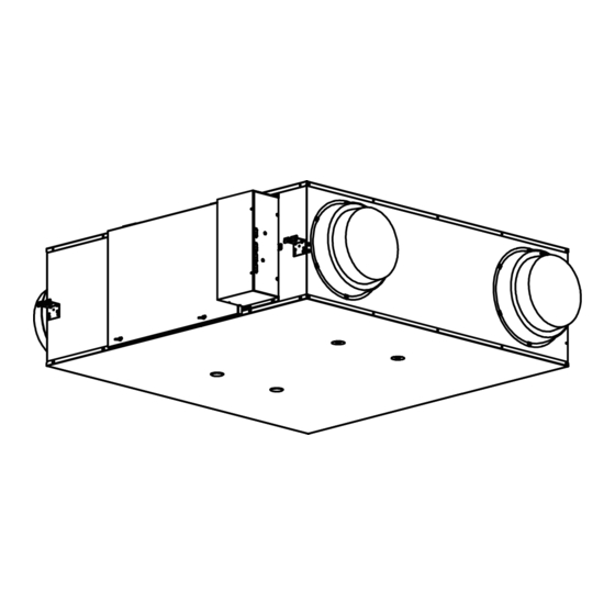
Energy Recovery Ventilator
Model No.
FV-15ZY1
FV-50ZY1
FV-1KZY1
INSTRUCTIONS
FV-25ZY1
FV-65ZY1
FV-1HZY1
CONTENTS:
SAFETY INSTRUCTIONS ····················· 2
INSTALLATION INSTRUCTIONS ············· 2~5
INSTALLATION AND OPERATING REQUIREMENTS · 5~6
PRODUCT FEATURES ······················· 6
SUPPLIED ACCESSORIES ···················· 7
PART NAMES AND DIMENSIONS ··········· 7~8
WORK BEFORE INSTALLATION ··············· 9
HOW TO INSTALL ····················· 10~15
TEST RUN ··························· 15~16
USE AND MAINTENANCE INSTRUCTIONS ··· 16~17
MAINTENANCE ······················· 18~20
WIRING DIAGRAM ···················· 21~22
TROUBLESHOOTING ······················ 22
SPECIFICATIONS ·························· 23
OPTIONAL ACCESSORIES ·················· 24
FV-35ZY1
FV-80ZY1
FV-2KZY1
Advertisement
Table of Contents

Related Manuals for Panasonic FV-15ZY1


Summary of Contents for Panasonic FV-15ZY1
-
Page 1: Table Of Contents
Thank you for purchasing this Panasonic product. Please read these instructions carefully before attempting to install, operate or service the Panasonic product. Please carefully read “INSTALLATION INSTRUCTIONS” (P.2~5) of this instructions before installation. Failure to comply with instructions could result in personal injury or property damage. -
Page 2: Safety Instructions
SAFETY INSTRUCTIONS Please observe strictly ■Disconnect power supply before maintenance. ■This product is not intended for use by persons (including children) with reduced physical, sensory or mental capabilities, or lack of experience and knowledge, unless they have been given supervision or instruction concerning use of the product by a person responsible for the safety. Children should be supervised to ensure that they do not play with the product. - Page 3 INSTALLATION INSTRUCTIONS WARNING Please install a suitable all-pole Avoid the back-flow of gas into the switch with a contact separation of room from an open flue with flammable gas or other open-fire more than 3 mm (site supplied). Please use the switch with rated appliances.
- Page 4 INSTALLATION INSTRUCTIONS CAUTION Do not operate together with open- The building structure and fixings burning appliance (e.g. gas or oil which are used to install the product furnaces). must have sufficient strength to Otherwise, it may cause support more than 5 times the carbon monoxide poisoning.
- Page 5 INSTALLATION INSTRUCTIONS CAUTION Heat-insulate the outdoor duct Do not install the product in an (including the indoor side, if environment where the indoor necessary) to prevent condensation. temperature is significantly lower than the outdoor temperature. If heat insulation is not adequate, condensate may enter the property Otherwise, it may cause condensation, causing damage.
-
Page 6: Product Features
INSTALLATION AND OPERATING REQUIREMENTS Using conditions & Precautions Using condition Be careful of frost and dew As shown in the following figure, it is supposed Outdoor air condition that a high temperature absorbing air condition A Temperature range -10 ℃ 40 ℃... -
Page 7: Supplied Accessories
The following accessories are provided with the product in the package. When you unpack, check if the accessories are all included. If not, please contact your dealer. Drawing Name and Purpose ① Installation and operating instructions ② Model label PART NAMES AND DIMENSIONS ■FV-15ZY1、FV-25ZY1、FV-35ZY1、FV-50ZY1、FV-65ZY1、FV-80ZY1、FV-1KZY1 Unit: mm Applicable duct Model No. diameter FV-15ZY1 144.5 107.5 Φ97.6 Φ150... - Page 8 PART NAMES AND DIMENSIONS ■FV-1HZY1、FV-2KZY1 Unit: mm Applicable duct Model No. diameter FV-1HZY1 1224 1141 1127 1004 808 185.5 Φ245 Φ300 Φ250 FV-2KZY1 1224 1368 1127 1231 808 185.5 Φ245 Φ300 Φ250 (Suspension point dimensions) (Exhaust Air) (Room Air) Main Sub unit Sub unit Main...
-
Page 9: Work Before Installation
(1)No other devices should be set inside the double dot scribing area, which is reserved for maintenance. (2)During reverse installation, the position of the inspection opening should also meet the dimensional relationship shown in Figure 2. Unit: mm Model No. FV-15ZY1 FV-25ZY1 FV-35ZY1 FV-50ZY1 FV-65ZY1 FV-80ZY1... -
Page 10: How To Install
HOW TO INSTALL ■Installation of energy recovery ventilator ①Installation diagram(Figure 1、Figure 2、Figure 3) ■FV-15ZY1、FV-25ZY1、FV-35ZY1、FV-50ZY1、FV-65ZY1、FV-80ZY1、FV-1KZY1 Support Support Pipe hood Pipe hood (Supply air) (Supply air) (Room air) (Room air) (Outside air) Room air duct (Exhaust air) (Exhaust air) (Outside Room air duct... - Page 11 HOW TO INSTALL Positioning and installation of supports (Figure 1) ② (1)Please set the supports according to the Nut (site supplied) support parts of the energy recovery ventilator. Washer (site supplied) (site supplied: M10-M12) (2)Install the support parts (4) of the energy recovery ventilator to the suspenders (site supplied).
- Page 12 Ground wire (Yellow and green) Notice Sheath ●For the remote control (optional) wiring arrangement, Unit: mm Figure 1 please refer to the installation and operating instructions of remote control for more details. ■FV-15ZY1 ■FV-65ZY1 ■FV-1HZY1 FV-25ZY1 FV-80ZY1 FV-2KZY1 FV-35ZY1 FV-1KZY1 Main unit FV-50ZY1...
- Page 13 HOW TO INSTALL When connecting the switch ■ Earth Wire clip terminal (Make sure the power cord is securely fastened) Power cord 源 开 Make sure connecting wires are securely fastened Damper Wire plug Terminal block Figure 4 (4) If you need to use the remote control (optional) with RS485 function, please connect the wire according to the wiring diagram in the instructions of the remote control.
- Page 14 H (High) or L (Low) volume volume Air volume Air volume Air volume Air volume (Pa) (Pa) setting 2 setting 1 setting 1 setting 2 H1(L1) (Factory set) FV-15ZY1 H2(L2) H3(L3) 43.5 H4(L4) FV-25ZY1 50.5 FV-35ZY1 24.5 FV-50ZY1 FV-65ZY1 34.5 26.5 FV-80ZY1 34.5 26.5...
-
Page 15: Test Run
HOW TO INSTALL Fix the screws removed in step ② (P.12) ⑧ 15ZY1 65ZY1 ■ ■ 1HZY1 ■ onto the cover of the electrical equipment 25ZY1 80ZY1 2KZY1 box again. (Figure 8) 35ZY1 1KZY1 Main unit 50ZY1 ... -
Page 16: Use And Maintenance Instructions
TEST RUN In case of any abnormality, please immediately turn the dedicated circuit breaker to "OFF" and ● confirm the wiring again. Situation Analysis Description The product does not start ● The OA damper will be This is normal. Please wait ●... - Page 17 USE AND MAINTENANCE INSTRUCTIONS WARNING Please entrust the dealer or similarly Do not turn the switch on/off when qualified person to repair the product there are combustible gas leaks. excluding filter maintenance. Sparks from the switch may cause gas Otherwise, it may cause the fire, electric explosion.
-
Page 18: Maintenance
MAINTENANCE CAUTION Please wear gloves during main- Please pay attention to the iden- tenance. tifier of the filter when cleaning or replacing the filter. The incisions of sheet metal and resin parts, as well as bulges and sharp Otherwise, the purification efficiency corners of the product, may cause may decrease. - Page 19 "A". Then slide and remove the inspection cover along the direction indicated by Butterfly bolt arrow "B". (Figure 2) Figure 1 FV-15ZY1~FV-1KZY1 FV-1HZY1、FV-2KZY1 Figure 2 Remove two (one set) outdoor filters (Figure 3) along the direction indicated by arrow "C". ③...
- Page 20 (Figure 5) The arrow should point to the heat exchange core. ※ Outdoor filter Outdoor filter Outdoor filter Heat exchange core FV-15ZY1~FV-1KZY1 FV-1HZY1、FV-2KZY1 Figure 5 CAUTION Fix the inspection cover by reversing the steps. ⑥ Please pay attention to the installation directions of the filters.Improper installation...
-
Page 21: Wiring Diagram
WIRING DIAGRAM Connect wires indicated by dashed lines. Please use the switch with rated current above 10 A. ■FV-15ZY1、FV-25ZY1、FV-35ZY1、FV-50ZY1 Second Unit *Power source and all-pole switch to be supplied to on and after second unit. ■FV-65ZY1、FV-80ZY1、FV-1KZY1 Second Unit *Power source and all-pole switch to be supplied to... -
Page 22: Troubleshooting
WIRING DIAGRAM ■FV-1HZY1、FV-2KZY1 Second Unit *Power source and all-pole switch to be supplied to on and after second unit. TROUBLESHOOTING Please check according to the following table. If the abnormality still exists, please power off the product and contact the dealer. Symptom Cause Troubleshooting... -
Page 23: Specifications
Exhaust air efficiency efficiency volume (%) (%) (Pa) (dB(A)) (kg) Cooling Heating Cooling Heating High FV-15ZY1 High FV-25ZY1 43.5 High FV-35ZY1 50.5 62.5 High FV-50ZY1 62.5 High FV-65ZY1 63.5 High FV-80ZY1 1000 High FV-1KZY1 1500 63.5... -
Page 24: Optional Accessories
FV-FP65ZY1 FV-80ZY1 FV-FP80ZY1 FV-1HZY1* FV-1KZY1 FV-FP1KZY1 FV-2KZY1* *For the FV-1HZY1 or FV-2KZY1 model, two sets are used each time. For other models, one set is used each time. Panasonic Corporation Web site: http://www.panasonic.com Issue date:05/2023 © Panasonic Corporation 2023 P0523-0 1KZY16853...