Table of Contents
Advertisement
Quick Links
INSTALLATION AND OPERATING INSTRUCTIONS
Remote Control for Energy Recovery Ventilator (ERV)
Thank you for purchasing this Panasonic product.
Please read these instructions carefully before attempting to install, operate or service the
Panasonic product.
Please carefully read "INSTALLATION INSTRUCTIONS" (P.2~3) of this instructions before
installation. Failure to comply with instructions could result in personal injury or property
damage. Please explain to users how to operate and maintain the product after installation,
and this booklet should be presented to users. Please carefully read "USE AND MAINTENANCE
INSTRUCTIONS" (P.12) of this instructions before operation.Please retain this booklet for
future reference.
Model No. FV-SWGR1
CONTENTS
SAFETY INSTRUCTIONS ........................................ 2
INSTALLATION INSTRUCTIONS ........................ 2~3
REQUIREMENTS ................................................... 4
SUPPLIED ACCESSORIES ....................................... 4
PART NAMES AND DIMENSIONS .......................... 4
HOW TO INSTALL ............................................ 5~7
TEST RUN ............................................................. 7
RS485 CONNECTION SETTINGS ....................... 7~8
LIST OF REGISTER ADDRESSES....................... 8~10
DESCRIPTION .............................................. 10~11
OPERATION ................................................. 11~12
USE AND MAINTENANCE INSTRUCTIONS ........... 12
TROUBLESHOOTING........................................... 13
WIRING DIAGRAM ............................................. 13
SPECIFICATIONS ................................................. 14
Advertisement
Table of Contents

Related Manuals for Panasonic FV-SWGR1


Summary of Contents for Panasonic FV-SWGR1
-
Page 1: Table Of Contents
TROUBLESHOOTING........... 13 WIRING DIAGRAM ..........13 SPECIFICATIONS ..........14 Thank you for purchasing this Panasonic product. Please read these instructions carefully before attempting to install, operate or service the Panasonic product. Please carefully read “INSTALLATION INSTRUCTIONS” (P.2~3) of this instructions before installation. -
Page 2: Safety Instructions
SAFETY INSTRUCTIONS Please observe strictly Disconnect power supply before maintenance. This product is not intended for use by persons (including children) with reduced physical, sensory or mental capabilities, or lack of experience and knowledge, unless they have been given supervision or instruction concerning use of the product by a person responsible for the safety. - Page 3 INSTALLATION INSTRUCTIONS WARNING Please use fixed wiring with a nominal Always isolate the power supply to all cross-sectional area of 1.5 mm per core the circuits before touching the and a rated voltage of 300 V/500 V or terminals or wiring. less as the control wire between the Otherwise, it may cause an electric shock.
-
Page 4: Installation And Operating Requirements
INSTALLATION AND OPERATING REQUIREMENTS The remote control can link up to 10 energy recovery ventilators. ● The mounting surface should be as flat as possible to prevent deformation of the ● product. (If the wall is not flat, the LCD screen may be damaged, or faults may occur.) Switch Box If the installation position is too high or too low, you may not be able to see the ●... - Page 5 HOW TO INSTALL 1-1. Connect the wire Draw out the control wire from the switch box, open the right back cover of the base, and connect the wire as illustrated in the Wiring Diagram. For details, please refer to the following figure or the attached Wiring Diagram.
- Page 6 HOW TO INSTALL(RS485 CONNECTION) 2-1. Connect the wire Low voltage connection (where the remote control is connected to the ERV): Refer to “1-1. Connect the wire” in the section “How to Install”. Extra-low voltage connection(where the remote control is connected to RS485): Open the left back cover, and refer to the figure below or the attached Wiring Diagram for details.
-
Page 7: How To Install
HOW TO INSTALL(RS485 CONNECTION) 2-4. Fix the base into the switch box Refer to “1-3. Fix the base into the switch box” in the section “How to Install”. 2-5. Fix the top cover Refer to “1-4. Fix the Top Cover” in the section “How to Install”. TEST RUN When installation is complete, turn on the power, press each of the function keys on the remote control to check if the ERV works correctly. -
Page 8: List Of Register Addresses
RS485 CONNECTION SETTINGS Communication frame structure Name Start Machine address Function code Data Check code Number of bytes Default interval Default interval Start: Set a default range of 3.65 ms or more between signals (without communication time). Machine address: Specify a machine address to connect the RS485 module. (Refer to “List of the machine addresses”... - Page 9 LIST OF REGISTER ADDRESSES Register Function Read/ Data length Data name Type Data value [Byte] address code Write 0x01: Low 0x03 UINT16 0x03: High Air volume 0x06 0x0003 0x10 0xFF: set Skip (keep the current setting) The time remaining 0x000B 0x03 UINT16 0~720h...
-
Page 10: Key Functions And Display Description
LIST OF REGISTER ADDRESSES Cases of Setting Communication Framework for the RS485 Device ■ When reading and writing the data of register addresses 0x0011 to 0x0013 for a device with 0x01 as its machine address. 0x0011: Set the time for TIMER ON. 0x0012: Set TIMER ON/Cancel the timer. -
Page 11: Operation
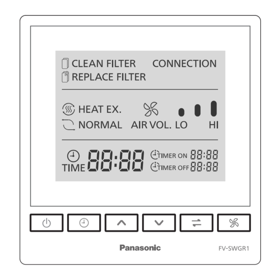
KEY FUNCTIONS AND DISPLAY DESCRIPTION Name Function Heat exchange/ Switches between heat exchange and normal ventilation. Normal ventilation key Air volume key Switches between the high and low volume. When the ERV has run for 720 hours, 1440 hours and 2160 hours, the CLEAN FILTER indicator CLEAN FILTER flashes. -
Page 12: Use And Maintenance Instructions
OPERATION When the number for the minute flashes, press to select a time for TIMER ON or TIMER OFF, and press the TIME key again to confirm the number of minutes. After that, press the TIME key again to finalise the TIMER ON or TIMER OFF mode, and the TIMER ON/OFF indicator will stay solid on. The time set for TIMER ON/OFF is now set. -
Page 13: Troubleshooting
TROUBLESHOOTING Phenomenon Solution The product does not work after Is the power supply connected? the standby switch is turned on. Is there a power failure? Is the power cord connection loose? The ERV does not act after Is the connection to the ERV correct? the remote control is operated. -
Page 14: Specifications
SPECIFICATIONS 220 V~ 50 Hz 2.0 W ﹣10 ℃~ 40 ℃ Panasonic Corporation Web Site: http://www.panasonic.com Issue date: 05/2023 Panasonic Corporation 2023 P0523-0 SWGR16857...