Panasonic PT-D7500U Operating Instructions Manual
Dlp based projector
Hide thumbs
Also See for PT-D7500U:
- Operating instructions manual (112 pages) ,
- Specifications (12 pages)
Table of Contents
Advertisement
Quick Links
DLP
TM
POWER
ON
OFF
AUTO
SETUP
RGB
RGB
1
2
AUX
SHUTTER
S-
VIDEO
VIDEO
SHUT
MENU
FREEZE
PAGE
UP
ENTER
DOWN
PAGE
ON SCREEN
1
2
3
SYSTEM
STD
OSD
SEL
D.ZOOM
FUNC
4
5
6
1
BRIGHT
CONTRAST
7
LENS
8
9
NEXT
ASPECT
0
USER
LIGHT
ID ALL
ID SET
LASER ON/OFF
Computer
Projector
Numetric
Read these instructions completely before operating this unit.
Based Projector
Operating Instructions
Commercial Use
PT-D7500U
Model No.
PT-D7600U
TQBJ 0113-3
Advertisement
Table of Contents

Related Manuals for Panasonic PT-D7500U


Summary of Contents for Panasonic PT-D7500U
- Page 1 Based Projector Commercial Use Operating Instructions PT-D7500U Model No. PT-D7600U POWER AUTO SETUP SHUTTER VIDEO VIDEO SHUT MENU FREEZE PAGE ENTER DOWN PAGE ON SCREEN SYSTEM D.ZOOM FUNC BRIGHT CONTRAST LENS NEXT ASPECT USER LIGHT ID ALL ID SET LASER ON/OFF...
-
Page 2: Important Safety Notice
This instruction booklet provides all the necessary operating information that you might require. We hope it will help you to get the most performance out of your new product, and that you will be pleased with your Panasonic DLP based projector. - Page 3 Model Number: PT-D7500U/PT-D7600U Trade Name: Panasonic Responsible Party: Matsushita Electric Corporation of America One Panasonic Way, Secaucus, NJ 07094 Telephone Number: 1-800-524-1448 or 1-800-526-6610 Email: pbtsservice@panasonic.com This device complies with Part 15 of the FCC Rules. Operation is subject to the...
-
Page 4: Table Of Contents
Contents IMPORTANT SAFETY NOTICE ......2 Adjusting the color temperature ........53 Adjusting color matching ..........54 Precautions with regard to safety ....5 Sharpness / Gamma / Noise reduction / Caution ..............6 Pulldown mode ..............55 Accessories ............7 To set the sRGB compliant picture........56 Precautions on handling ........8 To input BETACAM with YC 480i....56... -
Page 5: Precautions With Regard To Safety
Precautions with regard to safety WARNING If a problem occurs (such as no image) or if you notice smoke or a strange smell coming from the projector, turn off the power and disconnect the power cord from the wall outlet. •... -
Page 6: Caution
Precautions with regard to safety Do not place liquid containers on top of the projector. • If water spills onto the projector or gets inside it, fire or electric shocks could result. • If any water gets inside the projector, contact an Authorized Service Center. Do not insert any foreign objects into the projector. -
Page 7: Accessories
Do not look into the lens while the projector is being used. • Strong light is emitted from the projector’s lens. If you look directly into this light, it can hurt and damage your eyes. Do not bring your hands or other objects close to the air outlet port. •... -
Page 8: Precautions On Handling
Precautions on handling Precautions on transport Precautions on use To view clear images: The projection lens is susceptible to vibrations and impacts. Care should be taken to protect the lens from • The audience cannot enjoy high-contrast and vibrations and impacts when transporting. clear images if outside light or the illumination Precautions on installation interferes the screen surface.Draw window... -
Page 9: Examples Of System Expansion
Examples of system expansion The projector is provided with a number of terminals and optional accessories to enable various system expansions. Both input and output are provided to all terminals on the main unit. The following are some examples of system expansion: System 1 System 2 Stacking two projectors with the... -
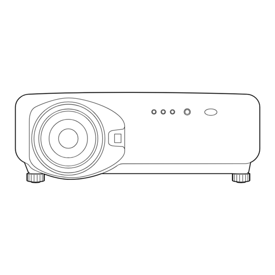
Page 10: Name And Function Of Parts
Name and function of parts Remote control POWER AUTO SETUP SHUTTER VIDEO VIDEO SHUT MENU FREEZE PAGE ENTER PAGE DOWN ON SCREEN SYSTEM D.ZOOM FUNC BRIGHT CONTRAST LENS NEXT ASPECT USER LIGHT ID SET ID ALL LASER ON/OFF Computer Projector Numetric <... - Page 11 POWER AUTO SETUP SHUTTER SHUT VIDEO VIDEO MENU FREEZE PAGE ENTER PAGE DOWN ON SCREEN SYSTEM D.ZOOM FUNC BRIGHT CONTRAST LENS NEXT ASPECT USER LIGHT ID ALL ID SET LASER ON/OFF Computer Projector Numetric <When the operation mode selector USER button Displays the sub-memory screen of the signal set to Computer>...
-
Page 12: Front And Side Of The Projector
Name and function of parts Front and side of the projector Side-mounted connection terminals (page 14) AC IN terminal (page 39) LAMP1 monitor (page 94) Connect the supplied line power cord into this This lamp lights up when the time to replace lamp receptacle. -
Page 13: Rear View Of The Main Unit
Rear view of the main unit Controls on rear panel AUTO SETUP RGB 1 RGB 2 VIDEO S-VIDEO SHUTTER LENS ENTER MENU Lamp unit housing door AUTO SETUP button (page 43) The lamp unit is housed. Pressing this button while projecting an image automatically corrects the picture positioning on Remote control receiver window (rear) (page 15) the screen. -
Page 14: Side-Mounted Connection Terminals
Name and function of parts Side-mounted connection terminals RS-232C (G) / RS-422 (R) RS-232C (G) / RS-422 (R) REMOTE 1 REMOTE 2 SERIAL S-VIDEO VIDEO RGB 1 IN RGB 2 IN / RGB 1 OUT SYNC/HD S-VIDEO IN terminal (pages 24 and 25) SERIAL OUT terminal (pages 26, 27, 78–80) An input terminal for S-video signals This terminal is an RS-232C/RS-422 compliant... -
Page 15: Using The Remote Control Unit
Using the remote control unit Loading dry cells Effective range of remote control operation When loading supplied AA dry cells into the battery compartment of the remote control, make sure that The remote control should normally be aimed at either their polarities are correct. -
Page 16: Setting Projector Id Number To Remote Control
Using the remote control unit Setting projector ID number to remote control Every projector has its ID number and the ID number button unless the NEXT button and a numeric button of the controlling projector must be set to the remote are pressed within five seconds after the ID SET control in advance so that the user can operate the button is pressed. -
Page 17: Using The Remote Control As A Pc Mouse
Using the remote control as a PC mouse Operation mode selector switch Put the knob to the Computer position. POWER AUTO SETUP • ENTER button SHUTTER Pressing the front, rear, left and right edges of the PAGE UP button VIDEO VIDEO SHUT MENU... -
Page 18: Installation
(ET-PKD75) (9.3") (Default position) Rear projection Table standing Ceiling mount Screen *For PT-D7500U, : Projection distance H= -0.2 x SH to SH : Height of the image 1.2 x SH SW: Image width For PT-D7600U, H : Vertical distance between the... -
Page 19: Projection Distances By The Type Of Projection Lenses (Optional)
19-22. Screen : Projection distance SH : Effective screen height Projection distances by the type of projection lenses (for PT-D7500U) • For the screen aspect ratio of 4:3 Units: m (feet/inches) Projection distance (L) - Page 20 Installation Projection distances by the type of projection lenses (for PT-D7500U) • For the screen aspect ratio of 16:9 Units: m (feet/inches) Projection distance (L) Screen dimensions Screen Zoom lens Fixed-focus lens size ET-D75LE4/SC(6.25-10.0 :1) ET-D75LE5 Effective Effective ET-D75LE1/SC(1.87-2.5 :1) ET-D75LE2/SC(2.5-3.75 :1)
- Page 21 Projection distances by the type of projection lenses (for PT-D7600U) • For the screen aspect ratio of 5:4 Units: m (feet/inches) Projection distance (L) Screen dimensions Screen Zoom lens Fixed-focus lens size ET-D75LE1/SC (1.5-2.0 :1) ET-D75LE2/SC (2.0-3.0 : 1) ET-D75LE3/SC (3.0-5.0 :1) ET-D75LE4/SC(5.0-8.0 :1) ET-D75LE5 Effective Effective...
- Page 22 Installation Projection distances by the type of projection lenses (for PT-D7600U) • For the screen aspect ratio of 16:9 Units: m (feet/inches) Projection distance (L) Screen dimensions Screen Zoom lens Fixed-focus lens size ET-D75LE4/SC (5.0-8.0 :1) ET-D75LE5 Effective Effective ET-D75LE1/SC (1.5-2.0 : 1) ET-D75LE2/SC (2.0-3.0 :1) ET-D75LE3/SC (3.0-5.0 :1) (inch)
- Page 23 If the projector is used with a screen size not listed in this manual, check the diagonal dimension (inch) of your screen and calculate the projection distance using the following formulas. Calculation formulas for projection distance by lens types (for PT-D7500U) Model number of projection lens Aspect ratio...
-
Page 24: Connection
Connection Before starting connection The pin-out and signal names of the S-VIDEO IN Before connection, read carefully the instruction terminal are shown in the diagram below. manual for the device to be connected. Turning off the power switch of the devices Signal Pin No. -
Page 25: Example Of Connecting With Video Devices
Example of connecting with VIDEO devices Video deck (TBC built-in) Color monitor Control PC RS-232C (G) / RS-422 (R) RS-232C (G) / RS-422 (R) REMOTE 1 REMOTE 2 SERIAL S-VIDEO VIDEO RGB 1 IN RGB 2 IN / RGB 1 OUT SYNC/HD Red (connected to P terminal) -
Page 26: Example Of Connecting With Personal Computers
Connection Example of connecting with personal computers Control PC PC or color monitor with RGB input terminals RS-232C (G) / RS-422 (R) RS-232C (G) / RS-422 (R) REMOTE 1 REMOTE 2 SERIAL S-VIDEO VIDEO RGB 1 IN RGB 2 IN / RGB 1 OUT SYNC/HD RS-232C (G) / RS-422 (R) RS-232C (G) / RS-422 (R) -
Page 27: Example Of Connecting With The Signal Selector
Example of connecting with the signal selector Notebook computer Video deck Control PC (TBC built-in) Signal selector Digital broadcasting DVD player tuner RS-232C (G) / RS-422 (R) RS-232C (G) / RS-422 (R) REMOTE 1 REMOTE 2 SERIAL S-VIDEO VIDEO RGB 1 IN RGB 2 IN / RGB 1 OUT SYNC/HD RS-232C (G) / RS-422 (R) -
Page 28: Installation Of Input Module (Optional)
Installation of input module (optional) Installing the input module Types of the input modules (optional) Prepare beforehand an input module (optional) compatible with the input signals of the system. Module model No Input signal Input signal level impedance of 75 Ω Image signal input: Synchronizing signal input: impedance of 75 Ω... - Page 29 Procedure of installation Disconnect the power before installing the input module. Remove the slot cover. Slot cover Remove 2 screws. Insert the input module. Slot Input module Fix the input module. Tighten the two screws. Register the input signal. • This projector needs to register the type of input signal after the installation of the input module.
-
Page 30: Connecting Signals To The Input Module
Installation of input module (optional) Connecting signals to the input module When installing the projector, it is necessary to connect signals to the input module in accordance with the connecting equipment. Refer to the following diagram to establish proper signal connection. Signal selector RS-232C RGB signal... -
Page 31: Connecting The Signal To The Analog Rgb Signal Input Module
Connecting the signal to the analog RGB signal input module An interface (D-SUB BNC) is necessary to connect the projector with a PC using an analog RGB signal input module. 1. Connecting analog RGB signals RGB signal input module (optional) ET-MD95RGB H/H·V RGB Module... -
Page 32: Connecting The Signals To The Video Signal Input Module
Installation of input module (optional) Connecting the signal to the video signal input module 1. Connecting the video signals Video signal input module (optional) ET-MD95VM2 LINE/Cr IN LINE OUT C/Cb IN Y IN Video Module ET-MD95VM2 Luminance Color Image signal signal signal Image signal... - Page 33 2. Connecting the component signals Video signal input module (optional) ET-MD95VM2 LINE/Cr IN LINE OUT Y IN C/Cb IN Video Module ET-MD95VM2 Luminance signals Y Color-difference Color-difference signals Cb signals Cr DVD player Video deck (TBC built-in) • For details on switching between the video signals connection and the component signals connection, refer to the section for switching the signals of ET-MD95VM2 (optional) on page 68.
-
Page 34: Connecting The Signal To The Serial Digital Signal Input Module
Installation of input module (optional) Connecting the signal to the serial digital signal input module Serial digital input module (optional) ET-MD95SD1 (for 480i/576i) 480i Module SERIAL ET-MD95SD1 SD signal SD signal output (active through) Business digital video deck • Insert the input module suitable for the input signal specifications. •... - Page 35 1. For 480p dual link (4:2:2p) SMPTE294M-compliant, 720x483 active line 59.94 Hz progressive scan 270 Mbps Serial digital input module (optional) ET-MD95SD2 (for 480p/480i/576i) MAIN IN MAIN OUT SUB IN SUB OUT 480p Module SERIAL ET-MD95SD2 SD signal MAIN MAIN (Link-B) (Link-A) (Link-A)
- Page 36 Installing the input module (optional) Serial digital input module (optional) ET-MD95SD3 (for HD SDI) 1080i/720p Module HD SERIAL ET-MD95SD3 HD SD signal HD SD signal output (active through) Business-use digital video deck • Insert the input module that meets the input signal specifications. •...
-
Page 37: Connecting Signals To The Dvi Signal Input Module
Connecting signals to the DVI signal input module DVI-D input module (optional) ET-MD75DV DVI-D IN DVI-D OUT DVI Module ET-MD75DV DVI signal PC with DVI output • Pin assignments and signal names of DIV-D input Pin No. Signal Pin No. Signal terminal are listed in the table at right (terminal for TMDS data 2–... -
Page 38: How To Install And Remove The Projection Lens (Optional)
How to install and remove the projection lens (optional) How to install the How to remove the projection lens projection lens While pressing the lock button on the While pressing the lock button on the projection lens cover, pull the cover projection lens cover, pull the cover forward to remove it. -
Page 39: Projection
Projection AUTO POWER SETUP AUTO SETUP SHUTTER RGB 1 RGB 2 VIDEO VIDEO SHUT MENU FREEZE VIDEO S-VIDEO SHUTTER PAGE LENS ENTER MENU ENTER PAGE DOWN ON SCREEN SYSTEM D.ZOOM FUNC BRIGHT CONTRAST LENS NEXT ASPECT USER LIGHT ID ALL ID SET LASER ON/OFF Computer... -
Page 40: Powering Off The Projector
Projection POWER AUTO AUTO SETUP SETUP SHUTTER VIDEO VIDEO SHUT RGB 1 RGB 2 MENU FREEZE VIDEO S-VIDEO SHUTTER PAGE ENTER LENS MENU ENTER PAGE DOWN ON SCREEN SYSTEM D.ZOOM FUNC BRIGHT CONTRAST LENS NEXT ASPECT USER LIGHT ID ALL ID SET LASER ON/OFF Computer... -
Page 41: How To Adjust The Lens
Adjustment range after lens position (optical shift) Do not move the lens beyond the bounds of the shift range as this may cause a change in the focus. This limitation is to protect the parts of the projector. PT-D7500U Floor projection Ceiling projection 0.28H... -
Page 42: How To Adjust The Lens For Addressing Unevenness Of Focusing
How to adjust the lens PT-D7600U Floor projection Ceiling projection Standard Standard projection projection position position Projected Projected 0.31H 0.31H 0.31H 0.31H screen width,H screen width,H How to adjust the lens for addressing unevenness of focusing If the image is out of focus in any portion of the screen, adjust the lens by turning the adjustment screws to obtain evenness of focusing. -
Page 43: Automatic Adjustment (Auto Setup)
Automatic adjustment (AUTO SETUP) Automatic adjustment function adjust the resolution, clock phase and image position automatically when dots- structured analog RGB signals such as computer signal are supplied. (Automatic adjustment is not available if signals or moving images other than analog RGB signals are supplied.) It is recommended to supply images with a bright white frame at the outermost periphery containing characters etc. -
Page 44: Registration Of Input Signal Data
Registration of input signal data The input signal data must be registered because it is not registered on shipment of the projector. • Up to 96 input signals can be registered. Note • Registration is performed by supplying the signal that corresponds to the mounted input module. Registration of new data When a new signal is supplied, press the MENU button on the remote control or operating section of the main unit, and a “NEW SIGNAL INPUTS”... -
Page 45: If New Registration Is Not Available Because Of Full Memory
If new registration is not available because of full memory: If the number of already registered signals is 96, or the memory is full when you entered a new signal, then press the MENU button of the remote control or the operating section of the main unit, and a “Confirm overwriting registration” screen appears. -
Page 46: Sub Memory
Registration of input signal data Sub memory The projector is provided with a sub memory function to register plural pieces of image adjustment data even they are determined to be the same signal by the frequency and form of the synchronization signal source. Use this function when the user needs adjustment of picture quality such as aspect switching and white balance using the same signal source. - Page 47 On-screen indications Input switching / signal switching This shows the registered signal name on the status screen for signal switching. NAME: MEMORY NO: A1 (1-2) S.S. NO: – – – INPUT NO: RGB1 Details of registered signal REGISTERED SIGNAL STATUS NAME: SXGA60-A1 The designation can be set by the sub memory items.
-
Page 48: Using The Freeze Function
Using the FREEZE function Pressing the “FREEZE” button of the remote control switches between a still image and a motion image. Still image Motion image Using the SHUTTER function If the projector is not used for a certain period of time during the meeting intermission, for example, a shutter mode is available that allows the user to hide images temporarily. -
Page 49: On-Screen Menus
On-screen menus Structure of menu screens Menus are extensively used for configuring, adjusting or reconfiguring the projector. The menus structure is as follows: MAIN MENU MAIN MENU PICTURE (pages 51-56) PICTURE POSITION LANGUAGE PICTURE OPTION PICTURE MODE STANDARD TEST PATTERN COLOR SIGNAL LIST TINT... -
Page 50: Basic Operations On Menu Screen
On-screen menus Basic operations on menu Returning to the previous screen screen • When the “MENU” is on the screen, pressing the Press the “MENU” button. “MENU” button returns to the previous page. The MAIN MENU appears on the screen. •... -
Page 51: Adjusting The Picture
Adjusting the picture Switching the picture mode The user can switch to the desired picture mode suitable for the image source and the environment in which this projector is used. Press the “MENU” button. MAIN MENU PICTURE The MAIN MENU screen will be displayed. POSITION Select “PICTURE”... -
Page 52: Adjusting Contrast / Bright / Color / Tint
Adjusting the picture The desired picture can be obtained by following the procedure below. Adjusting Contrast / Bright / Color / Tint Adjustment procedure – to adjust picture (color intensity) Press the “MENU” button. MAIN MENU PICTURE The MAIN MENU screen will be displayed. POSITION LANGUAGE Select “PICTURE”... -
Page 53: Adjusting The Color Temperature
Adjusting the color temperature Adjustment procedure (to be performed while projecting the signals to be adjusted) Press the “MENU” button. MAIN MENU PICTURE The MAIN MENU screen will be displayed POSITION LANGUAGE Select “PICTURE” with the OPTION buttons. TEST PATTERN SIGNAL LIST Press the “ENTER”... -
Page 54: Adjusting Color Matching
Adjusting the picture Adjusting color matching When multiple sets are used simultaneously, this projector allows the user to correct the difference of colors among the sets. Procedure of adjustment Press the “MENU” button. MAIN MENU PICTURE The MAIN MENU screen will be displayed. POSITION LANGUAGE Select “PICTURE”... -
Page 55: Sharpness / Gamma / Noise Reduction / Pulldown Mode
Sharpness / Gamma / Noise reduction / Pulldown mode Procedure of adjustment MAIN MENU PICTURE Press the “MENU” button. POSITION The MAIN MENU screen will be displayed. LANGUAGE OPTION Select “PICTURE” with the TEST PATTERN SIGNAL LIST buttons. :MENU SELECT ENTER:SUB MENU Press the “ENTER”... -
Page 56: To Set The Srgb Compliant Picture
Adjusting the picture To set the sRGB compliant picture sRGB is the international color reproduction standard (IEC61966-2-1) established by IEC (International Electrotechnical Commission). Perform the following setting procedure to reproduce the higher-fidelity picture in compliance with sRGB. 1. Set color matching adjustment to “OFF”. 2. -
Page 57: Adjusting The Position
Adjusting the position Desired position can be achieved by following the procedure below. Shift adjustment This function allows the user to adjust the picture position vertically or horizontally if the position of the image projected on the screen is displaced when the projector is properly positioned against the screen. Procedure of adjustment Press the “MENU”... -
Page 58: Size Adjustment
Adjusting the position Size adjustment Procedure of adjustment Press the “MENU” button. MAIN MENU PICTURE The MAIN MENU screen will be displayed. POSITION Select the “POSITION” with the LANGUAGE OPTION buttons. TEST PATTERN SIGNAL LIST :MENU SELECT ENTER:SUB MENU Press the “ENTER” button. POSITION The POSITION screen will be displayed. - Page 59 If the aspect ratio of the input signals is different from that of the panel, the pictures are displayed by converting it into the panels aspect ratio (4:3 for PT-D7500U and 5:4 for PT-D7600U). • VID AUTO: The projector identifies the video ID (VID) embedded in the picture signals and displays the picture by automatically switching the screen sizes between 4:3 and 16:9.
-
Page 60: Blanking Adjustment
Adjusting the position Blanking adjustment Blanking adjustment fine-tunes the images projected by the video deck or other devices when the noise appears on the edges of the screen or if a part of the image lies slightly offscreen. Procedure of adjustment Press the “MENU”... -
Page 61: Clock Phase Adjustment
Clock phase adjustment Clock phase adjustment achieves the best image when the screen flickers or halo is observed around the contour. Procedure of adjustment Press the “MENU” button. MAIN MENU PICTURE The MAIN MENU screen will be displayed POSITION Select the “POSITION” with the LANGUAGE OPTION buttons. -
Page 62: Adjusting The Input Resolution
Adjusting the position Adjusting the input resolution Input resolution adjustment achieves the best image when the screen flickers or halo is observed around the contour. Procedure of adjustment Press the “MENU” button. MAIN MENU PICTURE The MAIN MENU screen will be displayed. POSITION Select the “POSITION”... -
Page 63: Adjusting The Clamp Position
Adjusting the clamp position Use the clamp position adjustment to achieve the optimal value when dark areas of the image are crushed or displayed in green. Procedure of adjustment Press the “MENU” button. MAIN MENU PICTURE The MAIN MENU screen will be displayed. POSITION Select “POSITION”... -
Page 64: Keystone Distortion Correction
• The adjusted value is reflected in other input signals. • Keystone distortion can be corrected to ±40° of the angle of tilt for the projector against the screen. (If fixed-focus lens is used, the angle will be within ±27° for PT-D7500U and within ±22° for PT-D7600U.) -
Page 65: Edge Blending Adjustment
Edge blending adjustment This projector has the function to hide the seams for multi-screens. Procedure of adjustment Press the “MENU” button. MAIN MENU PICTURE The MAIN MENU screen will be displayed. POSITION Select the “POSITION” with the LANGUAGE OPTION buttons. TEST PATTERN SIGNAL LIST :MENU SELECT... -
Page 66: Changing The Display Language
Adjusting the position Select the “BRIGHT” with the BRIGHT ADJUST buttons. BRIGHT INSIDE BRIGHT OUTSIDE Press the ENTER button. UPPER The BRIGHT ADJUST screen will be displayed. LOWER Select the “BRIGHT INSIDE” with the LEFT RIGHT buttons. Adjust the compensation value (0-255) with the buttons. -
Page 67: How To Change The System Format
How to change the system format Pressing the SYSTEM SELECTOR button on the remote control or the control panel of the main unit allows the user to make the following changes depending on the currently selected input module. The name of the selected system such as RGB, YP and AUTO is displayed on the top left of the screen and disappears automatically. -
Page 68: How To Change The Signal For The Et-Md95Vm2 (Optional)
How to change the signal for the ET-MD95VM2 (optional) When ET-MD95VM2 (optional) is installed with the projector, select the signaling system according to the connected device. Procedure of setting Press the “MENU” button. MAIN MENU The MAIN MENU screen will be displayed. PICTURE POSITION Select “OPTION”... -
Page 69: How To Use Rgb Reality Mode
How to use RGB REALITY mode RGB REALITY mode converts RGB (primary colors) input signals into component signals and achieves the high- quality playback by motion-image-specific picture conversion process. This mode is effective only when the signal input is applied to the RGB input signal module (ET-MD95RGB). The appropriate mode can be selected according to the signal. -
Page 70: Optional Settings
Option settings ID number setting The projector has an ID number setting function that helps the user to control two or more projectors either simultaneously or separately with a single remote control. The ID number is set to "ALL" by default. Hence the ID number need not be set when only one projector is used. -
Page 71: Installation Setting
Installation Setting A projection scheme can be chosen depending on the installation of the projector. If the picture is shown upside down or in reverse, change the projection scheme using the following figures A to D. A: Floor mount front projection (Front – Floor mount) B: Ceiling mount front projection (Front –... -
Page 72: Lamp Select
Option settings Lamp select Lamp power Two internal lamps in the projector can be used either The luminance of the projection lamp can be changed in “DUAL” or “SINGLE” mode depending on user's depending on user's needs or the viewing conditions. needs or viewing conditions. -
Page 73: System Information
System information Fan control When using the projector over 1 400 m (4605.3') Displays the system information of the projector. above sea level, set to “High”. SYSTEM INFORMATION ROM VERSION: 1.00 FAN CONTROL NORMAL SET RUNTIME: LAMP1 RUNTIME: LAMP2 RUNTIME: HIGH INPUT BOARD: NOT YET... -
Page 74: P In P
Option settings P IN P • Type: The user can select the window that is displayed by This item is used to set the condition of the Picture-In- priority when two windows overlap. Picture. “MAIN WINDOW”: The main window is displayed by OPTION priority. -
Page 75: Setting Func1
List of P IN P RGB1 RGB2 ET-MD95RGB ET-MD95VM2 Subwindow Main window RGB input YCbCr input RGB1 YPbPr input RGB input RGB2 YCbCr input YPbPr input VIDEO input S-VIDEO input RGB input RGBrealiry input ET-MD96RGB YCbCr input YPbPr input LINE input ET-MD95VM2 Y / C input YCbCr input... -
Page 76: Setting The Contrast Mode
Setting the contrast mode This equipment has 2 mode types for adjusting to the use environment. Press the “MENU” button. MAIN MENU PICTURE The MAIN MENU screen will be displayed. POSITION Select “OPTION” with the LANGUAGE OPTION buttons. TEST PATTERN SIGNAL LIST :MENU SELECT ENTER:SUB MENU... -
Page 77: How To Switch The Input Impedance (Signal Level) Of The Synchronization Signal
How to switch the input impedance (signal level) of the synchronization signal When the ET-MD95RGB input module (sold separately) is mounted, the user can switch the input impedance (signal level) of the synchronization signal with the analog RGB input. Choose 75 Ω when connecting with the equipment whose synchronization output impedance is 75 Ω such as a signal selector, or switch to HI-Z (TTL) when connecting with the equipment whose synchronization output is TTL such as a video card of a PC. -
Page 78: Using The Serial Terminals
Using the serial terminals The main unit is equipped with SERIAL terminals located in its terminal section on the side, and this terminal is compliant with RS-232C. Also a serial output terminal is provided to enable plural projector control. Examples of connection Single projector Plural projectors <Terminal section on Projector 1>... -
Page 79: Procedure Of Setting Communication Conditions
Procedure of setting communication conditions Press the “MENU” button. MAIN MENU The MAIN MENU screen will be displayed. PICTURE POSITION Press buttons to select LANGUAGE OPTION “OPTION”. TEST PATTERN SIGNAL LIST :MENU SELECT ENTER:SUB MENU Press the “ENTER” button. OPTION The OPTION screen will be displayed. -
Page 80: Control Commands
Using the serial terminals Control commands When controlling the projector from a computer, the following commands are available: Command Function of command Remarks Power “ON” In standby mode, commands other than “PON” are invalid. • While the lamp is ON and being controlled, a “PON” command will not be accepted. Power “OFF”... -
Page 81: Using The Remote 2 Terminal
Using the REMOTE 2 terminal Using the REMOTE 2 terminal provided on the side of the main unit, it is possible to operate the projector from a control panel etc. furnished in a distant location where infrared remote control signal cannot be received. Example of a control panel layout Remote terminal External control... -
Page 82: Displaying The Internal Test Pattern
Displaying the internal test pattern The projector has seven types of internal test patterns to check the condition of the set. To display test patterns, follow the steps below. • Results of adjustment on the image, picture quality, position, size and other factors will not be reflected Note in test patterns. -
Page 83: How To Use Network Module (Optional)
How to use network module (optional) The network module of the projector (ET-MD75NT) is provided with a LAN interface to enable projector control from the Web browser of personal computer. In addition, the network module also fulfills automatic E-mail transmission function. It can send mail to a predefined E-mail address when the system malfunctions or when the lamp used hours reaches the set value. -
Page 84: Initial Setting Of Network Module
How to use network module (optional) Initial setting of network module Procedure of setting Press the “MENU” button. MAIN MENU The MENU screen will be displayed. PICTURE Select “OPTION” with the POSITION LANGUAGE buttons. OPTION TEST PATTERN SIGNAL LIST :MENU SELECT ENTER:SUB MENU OPTION Press the “ENTER”... - Page 85 Description Items Function Display of host name and setting Make alteration if necessary when to use the HOSTNAME DHCP server. DHCP client function Set the DHCP item to ON when to acquire an IP address automatically using the DHCP server. DHCP Set to OFF if DHCP server is not used.
-
Page 86: Accessing From The Web Browser
Activate the Web browser in the personal computer. Enter the IP address set by the projector into the URL input field of the Web browser. Enter “user1” in the user name field and enter “panasonic” (lower case) in the password field. - Page 87 Top page Control button Click this item, and a projector control page appears. Update button Click this item, and a projector firmware update page appears. E-mail setting button Click this item, and an E-mail setting page appears. Monitor information button Click this item, and the status of the Network setting button projector is displayed.
- Page 88 How to use network module (optional) Network setting page Select ON to enable the DHCP client function. Enter the IP address if DHCP server is not used. Enter the port number. Normally use the value of 80 as indicated. Enter the net mask if DHCP server is not used.
- Page 89 Status indication page Displays the status of input slot. Displays temperature of projector’s intake air. Displays temperature inside the projector. Displays temperature of projector exhaust. Displays the lamp lit hours. Displays used hours of the projector. Displays self-diagnosis information. Displays the firmware version of the projector main unit.
- Page 90 How to use network module (optional) E-mail setting page • This page allows the user to send mail to up to two mail addresses automatically. The user can enter the location of, for example, the installed projector Enter the IP address of Select “Enable”...
- Page 91 E-mail setting page (continuing) Select the conditions for sending E-mail. Error: an error is detected by self-diagnosis: Warning LAMP1: remaining lamp service time has reached the value set in the field on the right. Warning LAMP2: remaining lamp service time has reached the value set in the field on the right.
- Page 92 How to use network module (optional) Firmware update page (Only those personnel with expertise must execute firmware update.) Enter file name and press the Upload Enter the file name of the desired button, which starts transfer. It will firmware for updating. take some tens of seconds to finish transfer.
-
Page 93: Returning The Network Module Setting Back To The Factory Setting
Page for control of image files Folder selection button This button specifies the folder to store the image data. Display selection button This button selects the format of listing of images stored in the network module. Transmission button Transfers an image stored in the PC to the network module. -
Page 94: Indication Of Monitor Lamp
Indication of monitor lamp Three monitor lamps are provided at the top of main unit front to inform the user of the lamp replacement time and unusual internal temperature. These lamps indicate the degree of abnormality by combination of blinking and/or lighting lamps. -
Page 95: Cleaning And Replacement Of Air Filter
Cleaning and replacement of air filter If too much dust is deposited in the air filter, temperature inside the main unit will rise and the temperature monitor (TEMP) lamp blinks, eventually turning off the power supply. Clean the air filter section once every 100 hours or so as a guideline depending on the location of projector operation. -
Page 96: Replacement Of Lamp Unit
Replacement of lamp unit CAUTION Wait until the lamp is cooled sufficiently before replacing the lamp unit. Precautions on lamp unit replacement Timing of lamp unit Be careful when handling a light source lamp. replacement The lamp may burst if it is hit by solid objects or if it is dropped because of high air pressure The lamp used for the light source has its due life. -
Page 97: Procedure Of Lamp Unit Replacement
Procedure of lamp unit replacement Caution • After 1 500 hours of operating the same lamp, it is only possible to operate the unit for approximately 10 minutes. Steps 8 to 14 must be completed within ten minutes. 1. Turn the power off by following the steps on pages 39 ~ 40, remove the power plug and confirm that the surroundings of the lamp unit have cooled off. - Page 98 Replacement of lamp unit 8. Insert the power cord plug into the wall outlet and then press the MAIN POWER switch. Caution • If the power does not turn on (power indicator lamp (red) does not turn on) even after turning the MAIN POWER switch “I”, turn the MAIN POWER “...
-
Page 99: Before Asking For Service
Before asking for service … try to check the following points again. Symptoms Checkpoint • Is the power cord securely plugged in the receptacle? • Is the MAIN POWER switch put to the “ ” position? • Is power supply live at the receptacle? •... -
Page 100: Specifications
Horizontally 15.73 kHz/15.63 kHz, vertically 59.94 Hz/50 Hz For RGB signal Horizontally 15 kHz–100 kHz, vertically 24 kHz–120 kHz, Panasonic Intelligent Auto Scanning (PIAS) system Dot clock frequency 20 MHz–162 MHz For DVI-D signal (When DVI module (optional item) is mounted) VGA–S-XGA Dot clock frequency 25 MHz–112 MHz... - Page 101 Model No. PT-D7500U PT-D7600U Interface ports RGB2 input/RGB1 output terminal 1 set of high-density, D-sub 15p (female) [For YP input] Y: 1.0 V [p-p] synchronization signal included, : 0.7 V[p-p] 75 Ω [For RGB input] 0.7 V[p-p] 75 Ω For G-SYNC: 1.0 V[p-p] 75 Ω...
-
Page 102: Appendix
1280 x 1024 for display. • The number of displayed dots of PT-D7500U is 1024 x 768. Those combinations listed in the above table that exceed these limits will be converted into 1024 x 768 for display. -
Page 103: Outside Dimensions
Outside dimensions <Units: mm(inch)> 530 (20.8") Note: Purchase of this equipment includes the rights to use this software (the built-in microcomputer and information recorded on ROMs) but does not grant copyrights. Do not reverse engineer, change or modify the software. The guarantee will not be valid for any malfunctions caused by such actions. -
Page 104: Français Information
NOTES IMPORTANTES CONCERNANT LA SÉCURITÉ AVERTISSEMENT: POUR RÉDUIRE LES RISQUES DE FEU OU DE CHOC ÉLECTRIQUE, NE PAS EXPOSER CE PRODUIT À L’EAU OU À L’HUMIDITÉ CAUTION RISK OF ELECTRIC SHOCK. DO NOT OPEN AVIS: RISQUE DE CHOC ÉLECTRIQUE NE PAS OUVRIR. VORSICHT: ZUR VERMEIDUNG EINES ELEKTRISCHEN SCHLAGES GERÄT NICHT ÖFFNEN. - Page 105 Précautions concernant la sécurité AVERTISSEMENT En cas de problème (pas d’image), ou si le projecteur dégage de la fumée ou une odeur étrange, éteindre l’appareil et débrancher immédiatement la fiche d’alimentation de la prise de courant. • Ne pas continuer d’utiliser le projecteur dans ces cas, autrement cela peut entraîner un incendie ou des chocs éIectriques.
- Page 106 Précautions concernant la sécurité Brancher la fiche du cordon d’alimentation fermement dans la prise de courant. • Si la fiche n’est pas complètement insérée, cela peut entraîner des chocs électriques ou la faire surchauffer. • Si la fiche est endommagée ou la plaque de la prise est desserrée, elles ne devraient pas être utilisées. Ne pas placer le projecteur sur des surfaces instables.
- Page 107 Lors de l’insertion de la pile, s’assurer que les polarités (+ et -) sont correctes. • Si la pile est insérée incorrectement, elle peut éclater ou fuire et cela peut causer un incendie, des blessures ou la contamination du compartiment des piles. N’utiliser que la pile indiquée.
- Page 108 Précautions pour la manipulation Précautions pour le transport Précautions pour l'utilisation Si le projecteur est utilisé en continu pendant plus de L'objectif de projection est sensible aux vibrations et huit heures, un réglage spécial est requis. Consulter aux impacts. Le protéger contre les vibrations et les un agent de service.
- Page 109 Remplacement de la lampe CAUTION Attendez que la lampe soit refroidie pour effectuer le remplacement. Précautions pour le remplacement de la lampe Période de remplacement Soyez prudent en manipulant la lampe source de la lampe de lumière. La lampe peut éclater si elle est heurtée par des objets solides ou si elle tombe La lampe utilisée comme source lumineuse dans le à...
- Page 110 Remplacement de la lampe Procédure de remplacement de la lampe Attention • Au bout de 1 500 heures de fonctionnement pour une même lampe, le projecteur ne peut plus fonctionner que pendant environ 10 minutes. 10 minutes. Les étapes 8 à 14 doivent être achevées en moins de dix minutes.
- Page 111 8. Branchez la fiche du cordon d'alimentation dans la prise murale et actionnez l'interrupteur MAIN POWER. Attention • Si la mise sous tension ne s'effectue pas (le témoin d'alimentation (rouge) ne s'éclaire pas) bien que vous ayez positionné l'interrupteur principal sur “ I ”, replacez l'interrupteur principal sur “ ”, vérifiez que la lampe et son cache sont correctemrnt installés et effectuez une nouvelle fois la mise sous tension.
- Page 112 Professional/Industrial Video Panasonic Broadcast & Television Systems Company Division of Matsushita Electric Corporation of America One Panasonic Way 4E-7 Secaucus, NJ 07094 (201) 392-4443 3330 Cahuenga Blvd West Los Angels, CA 90068 (323) 436-3500 Technical Support: (800) 524-1448 (800) 526-6610 FAX: (201) 392-6514 E-Mail: pbtssupport@panasonic.com...