Table of Contents
Advertisement
Quick Links
TABLE OF CONTENTS
1 Safety Precautions----------------------------------------------- 2
2 Specifications ----------------------------------------------------- 2
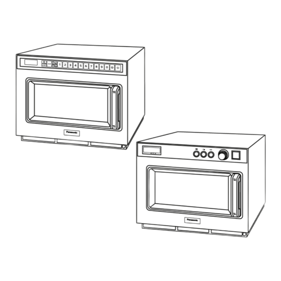
3 Location of Controls and Components ------------------- 3
4 Operating Instructions------------------------------------------ 5
5 Test Mode ----------------------------------------------------------18
6 Troubleshooting Guide ----------------------------------------20
7 Disassembly and Assembly Instructions ---------------23
8 Measurements and Adjustments---------------------------27
9 Wiring Connection Diagram ---------------------------------28
10 Schematic Diagram ---------------------------------------------29
11 Exploded View and Replacement Parts List -----------30
Model No.
Model No.
Destination : Continental Europe Countries
PAGE
© Panasonic Corporation 2022 Unauthorized copy-
ing and distribution is a violation of law.
Order Number MOD2203608CE
Microwave Oven
NE-2153-2EYG
NE-2143-2EYG
Advertisement
Table of Contents

Related Manuals for Panasonic NE-2153-2EYG


Summary of Contents for Panasonic NE-2153-2EYG
-
Page 1: Table Of Contents
7 Disassembly and Assembly Instructions ---------------23 8 Measurements and Adjustments---------------------------27 9 Wiring Connection Diagram ---------------------------------28 10 Schematic Diagram ---------------------------------------------29 11 Exploded View and Replacement Parts List -----------30 © Panasonic Corporation 2022 Unauthorized copy- ing and distribution is a violation of law. -
Page 2: Safety Precautions
1 Safety Precautions 2 Specifications Models: NE-2143-2 NE-2153-2 Power Source: 50 Hz, single phase 230V 50 Hz, single phase 230V Power Requirement: 14.3A 3160W 14.3A 3160W *Output: HIGH P10: 2100 W* 2100 W* MEDIUM P9: 90% HIGH P8: 80% --------------- P7: 70% P6: 60% MEDIUM... -
Page 3: Location Of Controls And Components
3 Location of Controls and Components 3.1. Outline diagram... -
Page 5: Operating Instructions
4 Operating Instructions 4.1. Operation procedure... -
Page 18: Test Mode
5 Test Mode 5.1. Component test procedure 5.1.2. High voltage capacitor 1. Check continuity of capacitor with meter on highest OHM scale. 2. A normal capacitor will show continuity for a short time, and then indicate 9MΩ once the capacitor is charged. 3. - Page 19 5.1.4. Diode 5.1.7. Temp sensor (Thermal protector) 1. Isolate the diode from the circuit by disconnecting the A temp sensor is mounted on exhaust guide. Its purpose is to leads. automatically shut off the oven in case the cavity overheats for 2.
-
Page 20: Troubleshooting Guide
6 Troubleshooting Guide 6.1. Cautions to be observed when troubleshooting Unlike many other appliances, the microwave oven is high-volt- age, high-current equipment. Though it is free from danger in ordinary use, extreme care should be taken during repair. 6.1.1. Check the grounding Do not operate on a 2-wire extension cord. - Page 21 6.1.7. Confirm after repair 1. After repair or replacement of parts, make sure that the screws of the oven, etc. are neither loose nor missing. Microwave might leak if screws are not properly tight- ened. 2. Make sure that all electrical connections are tight before inserting the plug into the wall outlet.
- Page 22 6.2. Troubleshooting guide...
-
Page 23: Disassembly And Assembly Instructions
7 Disassembly and Assembly Instructions 7.1. Magnetron (Upper and Lower) Upper magnetron 1. Discharge electric charge remaining on the high voltage capacitors. 2. Remove the entire rear panel by removing screws as shown. 3. Disconnect all lead wires from magnetron and thermal cutout. - Page 24 7.3. Digital programmer circuit board (PCB AU) NOTE: Please use care in handling the PCB AU to avoid damage. 1. Disconnect 2 flat cables from PCB AU. 2. Disconnect all of the connector from PCB AU. 3. Remove 2 screws holding PCB AU to detach it from its mounting bracket.
- Page 25 7.5. Upper antenna 7.6. Floor shelf and Lower antenna 1. To remove the floor shelf, insert a screwdriver through the small opening on the left side of the oven cavity and care- fully lift the floor shelf. 2. For removal of lower antenna, use the same procedure as upper antenna.
- Page 26 7.7. Temp sensor (Thermal protector) 1. Cut 2 lead wires at the top of sensor terminals. 2. Remove 2 screws holding temp sensor and replace with a new temp sensor. 3. Solder the lead wires securely to the sensor terminals. 7.8.
-
Page 27: Measurements And Adjustments
8 Measurements and Adjustments 8.1. Measurements and adjustments 8.1.1. Adjustment of Primary interlock switch, Secondary interlock switch and Interlock monitor switch 1. When mounting Primary interlock switch, Secondary interlock switch and Interlock monitor switch to Door hook (U), mount the Primary interlock switch, the Secondary interlock switch and the Interlock monitor switch to the Door hook (U) as shown in the figure. -
Page 28: Wiring Connection Diagram
9 Wiring Connection Diagram NOTE: When replacing, check the lead wire colour as shown. -
Page 29: Schematic Diagram
10 Schematic Diagram... -
Page 30: Exploded View And Replacement Parts List
11 Exploded View and Replacement Parts List 11.1. Exploded view and parts list NE-2153-2EYG,NE-2143-2EYG... - Page 31 AIR GUIDE B LOWER A4091-3290 SCREW FOR AIR FILTER FLAME A41073980AP EXHAUST GUIDE B ANE50328U0AP MAGNETRON BRACKET A603L3G1AEU D.P.CIRCUIT (U) NE-2153-2EYG, PCB AU A603L3G2AEU D.P.CIRCUIT (U) NE-2143-2EYG, PCB AU F60408U0AP OVEN LAMP SHEET A61454210AP THERMAL CUTOUT FOR MAGNETRON ANE60708U0BP INSULATION SHEET A...
- Page 32 XNW5EFN H0922000AI CUSHION RUBBER C H0922000AP CUSHION RUBBER C H0922000AY CUSHION RUBBER C XTWA4+8BJ SCREW NE-2153-2EYG, (4X8) FOR MEMBRANE SWITCH A393C3318GP DOOR HOOK (U) H01703F90EU DOOR LABEL H0922000CE CUSHION RUBBER C FOR OVEN (U) (BOTTOM PLATE) H0961000CJ CUSHION RUBBER D...
- Page 33 11.2. DOOR ASSEMBLY Safety Ref. Part No. Part Name & Description Pcs/set Remarks F3003CL00XPS DOOR FRAME (U) H3007-3J00 HINGE F301ACL00XP DOOR A H301H-3850 DOOR KEY LEVER B F301Q-3500 DOOR EU NOT INCLUDE DOOR SCREEN A H3018-3850 DOOR KEY H3019-3850 DOOR KEY B F3021CL00XP DOOR KEY SPRING ANE30562Q0AP...
- Page 34 11.3. ESCUTCHEON BASE ASSEMBLY NE-2153-2EYG NE-2153-2EYG Safety Ref. Part No. Part Name & Description Pcs/set Remarks A80163F80AP SPACER A603M-3J0A PC BOARD B (U) PCB BU H630Y3F90EUS MEMBRANE SWITCH A6590-3E20 FLAT CABLE H801N8U0APS ESCUTCHEON A (U) H80023E20P6 ESCUTCHEON B H80063E20P6 ESCUTCHEON D...
- Page 35 NE-2143-2EYG NE-2143-2EYG Safety Ref. Part No. Part Name & Description Pcs/set Remarks A603M-3J0A PC BOARD B (U) PCB BU ANE605Q8Y0BP PC BOARD F (U) PCB FU ANE61424L0AG MICRO SWITCH H61628Y0BP START SWITCH BRACKET ANE62648Y0BP SELECT SWITCH BUTTON A608C3G0AEUS TIMER KIT A6590-3E20 FLAT CABLE A800D3G00EU...
- Page 36 11.4. PACKING AND ACCESSORIES Safety Ref. Part No. Part Name & Description Pcs/set Remarks H00033F90EU INSTRUCTION BOOK H01023G10EUS PACKING CASE,PAPER NE-2153-2EYG H01023G20EUS PACKING CASE,PAPER NE-2143-2EYG H01043F90EU UPPER FILLER H01053F90EU LOWER FILLER H01065200AP VINYL COVER H01072Q00AP DOOR SHEET B H01083C00BP TRAY PACKING...
- Page 37 11.5. WIRING MATERIAL Safety Ref. Part No. Part Name & Description Pcs/set Remarks F030A3F90EU LEAD WIRE HARNESS A0KG00000169 FERRITE CORE A03523F90BP LEAD WIRE...