Table of Contents
Advertisement
Available languages
Available languages
Quick Links
AIR CONDITIONER (SPLIT TYPE)
Installation Manual
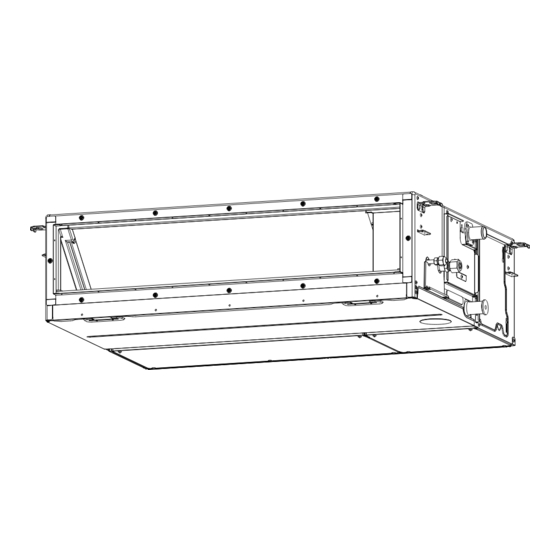
Indoor Unit
Model name:
Concealed Duct Type
RAV-GE1301BP Series
RAV-GE1801BP Series
RAV-GE2401BP Series
RAV-GE3001BP Series
RAV-GE3601BP Series
RAV-GE4001BP Series
RAV-GE4201BP Series
RAV-GE4801BP Series
RAV-GE6001BP Series
1116950140_00_cover.indd C1
1116950140_00_cover.indd C1
For commercial use
Untuk keperluan komersil
สํ า หรั บ ใช ง านเชิ ง พาณิ ช ย
1116950140
Installation Manual
1
English
Bahasa
Petunjuk Pemasangan
26
indonesia
ภาษาไทย
คู ม ื อ การติ ด ตั ้ ง
51
11/8/18 1:56 PM
11/8/18 1:56 PM
Advertisement
Chapters
Table of Contents

Related Manuals for Toshiba RAV-GE1301BP Series


Summary of Contents for Toshiba RAV-GE1301BP Series
- Page 1 Installation Manual For commercial use Indoor Unit Untuk keperluan komersil สํ า หรั บ ใช ง านเชิ ง พาณิ ช ย Model name: Concealed Duct Type RAV-GE1301BP Series RAV-GE1801BP Series RAV-GE2401BP Series RAV-GE3001BP Series RAV-GE3601BP Series RAV-GE4001BP Series RAV-GE4201BP Series...
-
Page 2: Table Of Contents
– 1 – Contents Original instruction Please read this Installation Manual carefully before installing the Air Conditioner. • This Manual describes the installation method of the indoor unit. Precautions for safety..........3 •... - Page 3 Clothing to provide protection from electric shock • The qualified installer is a person who installs, maintains, relocates and removes the air conditioners made by Toshiba Carrier Corporation. He or she has been trained to install, maintain, relocate and remove the air Work done at...
-
Page 4: Precautions For Safety
– 3 – Warning indications on the air conditioner unit Precautions for safety The manufacturer shall not assume any liability for the damage caused by not observing the description of this manual. WARNING WARNING WARNING ELECTRICAL SHOCK HAZARD ELECTRICAL SHOCK HAZARD Disconnect all remote General Disconnect all remote electric power supplies before servicing. - Page 5 • Do not touch the aluminium fi n of the unit. You may injure Selection of installation location yourself if you do so. If the fi n must be touched for some • When the air conditioner is installed in a small room, provide reason, fi...
- Page 6 – 5 – • Follow the instructions in the Installation Manual to install the • Nitrogen gas must be used for the airtight test. air conditioner. Failure to follow these instructions may cause • The charge hose must be connected in such a way that it is not the product to fall down or topple over or give rise to noise, slack.
- Page 7 Test run Relocation • Before operating the air conditioner after having completed the • Only a qualifi ed installer(*1) or qualifi ed service person(*1) is work, check that the electrical control box cover of the indoor allowed to relocate the air conditioner. It is dangerous for the air unit and service panel of the outdoor unit are closed, and set conditioner to be relocated by an unqualifi...
-
Page 8: Accessory Parts
– 7 – Accessory parts Selection of installation place Accessory parts Avoid installing in the following places Select a location for the indoor unit where the cool or warm air will circulate evenly. Avoid installation in the following kinds of locations. ’... -
Page 9: Installation
Installation under high-humidity atmosphere Installation In some cases including the rainy season, especially inside of the ceiling may become high-humidity atmosphere (dew-point temperature: 23 °C or higher). CAUTION 1. Installation to inside of the ceiling with tiles on the roof 2. - Page 10 – 9 – Installation of hanging bolt Installation of indoor unit Mounting filter rails and filters Consider the piping / wiring after the unit is hung to Treatment of ceiling Mount the filter rail so that the hooks fit into the corresponding holes. determine the location of the indoor unit installation The ceiling differs according to structure of building.
-
Page 11: Drain Piping
Gravitational drainage Drain piping Reattach the drain cap. CAUTION * For gravitational drainage, remove the white connector Following the Installation Manual, perform the drain piping work so that water is properly drained. Apply a (CN504) on the upper left of the circuit board in the electrical Upper pipe heat insulation so as not to cause a dew condensation. - Page 12 – 11 – Check the draining Heat insulating process In the test run, check that water drain is properly performed and water does not leak from the connecting part of As shown in the figure, cover the flexible hose and hose band with the attached heat insulator up to the bottom the pipes.
- Page 13 Fan characteristics GE130, GE180 GE240, GE300, GE360 Standard air volume: 800 m Standard air volume: 1200 m Lower limit of external Lower limit of external static pressure (120 Pa) static pressure (120 Pa) High (120 Pa) Upper limit of Upper limit of external static external static High...
-
Page 14: Duct Design
– 13 – Duct design Arrangement (Unit: mm) Referring to the following dimensions, manufacture duct at the local site. GE130, GE180 GE240, GE300, GE360 GE400, GE420, GE480, GE600 <Under air intake> <Under air intake> <Under air intake> 959.4 1359.4 659.4 37.5 37.5 37.5... -
Page 15: Refrigerant Piping
Evacuation Refrigerant piping CAUTION Do not scratch the inner surface of the flared part Perform vacuuming from the charge port of valve of the Connecting refrigerant piping when removing burrs. outdoor unit by using a vacuum pump. CAUTION Flare processing under the condition of scratches on For details, follow to the Installation Manual attached to the inner surface of flare processing part will cause the outdoor unit. -
Page 16: Electrical Connection
– 15 – Heat insulation process Electrical connection Apply heat insulation for the pipes separately at liquid side and gas side. For the heat insulation to the pipes at gas side, be sure to use the material with heat-resisting temperature 120 °C or higher. - Page 17 Wiring between indoor unit and outdoor unit Wire connection 1. Figure below shows the wiring connections between the indoor and outdoor units and between the indoor units REQUIREMENT and remote controller. The wires indicated by the broken lines or dot-and-dash lines are provided at the locally. 2.
-
Page 18: Applicable Controls
– 17 – External static pressure Applicable controls Each time button is pushed, indoor settings unit numbers in the control group change cyclically. Select the indoor unit to change Basic procedure for changing REQUIREMENT settings for. <Change on wired remote controller> settings The fan of the selected unit runs and the louvers When you use this air conditioner for the first... - Page 19 External static pressure Filter sign setting Push TIME buttons, to adjust the setting of power level. When using the wireless remote controller According to the installation condition, the filter sign Each push of the button changes the power To set up the external static pressure, use the DIP switch on the circuit board of the wireless reception part. term (Notification of filter cleaning) can be changed.
- Page 20 – 19 – Remote controller switch Group control for system of multiple units Push button to return to the normal One remote controller can control maximum 8 indoor units as a group. monitoring function display. Group control in single system Indoor unit data This function is available to call the service monitor Outdoor unit...
-
Page 21: Auto Restart Setting
To recognize the position of the Auto restart setting After confirmation, push button to return corresponding indoor unit though the to the normal mode. When button is pushed, the display indoor UNIT No. is known This product is designed so that, after a power failure, disappears and the status becomes the Check the position during operation stop. -
Page 22: Test Run
– 21 – When a test run is not Test run Wireless remote controller performed properly When TEMPORARY button is pushed for Before test run Wired remote controller 10 seconds or more, “Pi!” sound is heard When a test run is not performed properly, refer and the operation changes to test run. -
Page 23: Maintenance
Maintenance Periodic Maintenance For environmental conservation, it is strongly recommended that the indoor and outdoor units of the air conditioner in use be cleaned and maintained regularly to ensure efficient operation of the air conditioner. <Daily maintenance> When the air conditioner is operated for a long time, periodic maintenance (once a year) is recommended. Furthermore, regularly check the outdoor unit for rust and scratches, and remove them or apply rustproof Cleaning of air filter treatment, if necessary. -
Page 24: Troubleshooting
– 23 – Check codes and parts to be checked Troubleshooting Wired Wireless remote controller remote Confi rmation and check Confirmation of error log Sensor block display of controller receiving unit Judging display Main defective parts Parts to be checked / error description conditioner device When an error occurred in the air conditioner, an error... - Page 25 Wired Wired Wireless remote controller Wireless remote controller remote remote Sensor block display of Sensor block display of controller controller receiving unit receiving unit Judging Judging display display Main defective parts Parts to be checked / error description conditioner Main defective parts Parts to be checked / error description conditioner device...
-
Page 26: Appendix
– 25 – Appendix 5. When a commercially available dryer is attached to the Work instructions existing pipes. The existing R22 and R410A piping can be reused for There is the possibility that copper green rust has inverter R32 product installations. Existing pipes: Cannot be used. - Page 27 Petunjuk asli Baca Petunjuk Pemasangan ini secara cermat sebelum memasang AC ini. • Petunjuk ini menjelaskan cara memasang unit indoor. Petunjuk keselamatan..........28 •...
- Page 28 Toshiba Carrier Corporation. Mereka telah dilatih untuk memasang, merawat, memindahkan, ketinggian Helm untuk penggunaan dalam industri dan melepas AC yang dibuat oleh Toshiba Carrier Corporation atau, dengan kata lain, mereka telah (50 cm atau lebih) mendapat petunjuk dalam hal pekerjaan demikian oleh orang yang terlatih sehingga telah sangat menguasai pengetahuan yang terkait dengan pekerjaan-pekerjaan ini.
-
Page 29: Petunjuk Keselamatan
Petunjuk keselamatan Pesan peringatan pada Unit AC ■ Produsen tidak bertanggung jawab atas kerusakan akibat tidak Indikasi peringatan Penjelasan mematuhi penjelasan dalam petunjuk ini. WARNING PERINGATAN PERINGATAN ELECTRICAL SHOCK HAZARD BAHAYA TERSENGAT LISTRIK Disconnect all remote Umum Lepas sambungan semua catu daya listrik sebelum melakukan servis. electric power supplies before servicing. - Page 30 – 29 – • Jangan menyentuh sirip-sirip aluminium unit. Menyentuh sirip • Jangan memasang AC di lokasi tempat kebocoran gas bisa tersebut dapat membuat Anda terluka. Jika terpaksa Anda terjadi. Jika gas bocor dan terakumulasi di sekitar unit, gas harus menyentuh sirip tersebut, gunakan sarung tangan dapat tersulut dan menyebabkan kebakaran.
- Page 31 • Lakukan pekerjaan pemasangan sebagaimana ditentukan Sistem kelistrikan untuk melindungi dari kemungkinan angin topan dan gempa • Hanya pemasang berkualifi kasi(*1) atau petugas teknisi bumi. Jika AC tidak dipasang dengan benar, unit AC dapat servis yang berkualifi kasi(*1) yang diperbolehkan menangani roboh atau jatuh, sehingga menyebabkan kecelakaan.
- Page 32 – 31 – • Pekerjaan pengawatan kelistrikan harus dilakukan sesuai • Selesai pemasangan, gunakan Pedoman Pemilik untuk dengan hukum dan peraturan di masyarakat dan petunjuk menjelaskan cara menggunakan dan merawat unit kepada pemasangan. pengguna Pekerjaan yang tidak dilaksanakan dengan cara demikian dapat Pemindahan menyebabkan kematian akibat tersengat listrik atau hubungan •...
-
Page 33: Komponen Aksesori
Memilih lokasi pemasangan Komponen aksesori Hindari memasang di tempat-tempat berikut ini. Komponen aksesori ■ Pilih lokasi untuk unit indoor di mana udara sejuk atau hangat akan bersirkulasi secara merata. Hindari memasang di jenis-jenis tempat berikut ini. Daerah berair asin (daerah pantai). •... -
Page 34: Pemasangan
– 33 – Pemasangan Pemasangan dalam atmosfer berkelembaban tinggi ■ Dalam beberapa keadaan termasuk dalam musim penghujan, terutama di dalam langit-langit, atmosfer dapat menjadi sangat lembab AWAS (suhu titik embun: 23 °C atau lebih). 1. Pemasangan di dalam langit-langit dengan atap ubin Patuhi dengan ketat aturan berikut untuk mencegah kerusakan pada unit indoor dan juga cedera. - Page 35 Memasang baut gantung Pemasangan unit indoor Memasang rel filter dan filter ■ ■ ■ Pertimbangkan pemipaan / pengabelan setelah unit • Perlakuan untuk langit-langit Pasang rel filter sehingga kaitnya terpasang pas ke dalam lubang yang sesuai. tergantung untuk menentukan lokasi pemasangan Langit-langit berbeda-beda berdasarkan struktur dan orientasi unit indoor.
-
Page 36: Pipa Kuras
– 35 – Pipa kuras Drainase gravitasi ■ Pasang kembali tutup kuras. AWAS * Untuk drainase gravitasi, lepaskan konektor putih (CN504) di kiri atas papan rangkaian di Ikuti Petunjuk Pemasangan, jalankan kerja pipa kuras sehingga air benar-benar dikeringkan. Aplikasikan dalam kotak kontrol listrik. Pipa atas insulasi panas sehingga tidak menyebabkan kondensasi embun. - Page 37 Memeriksa pengurasan Proses insulasi panas ■ ■ Pada uji pengoperasian, periksa apakah pengurasan air dijalankan dengan benar dan air tidak bocor dari • Sebagaimana yang diperlihatkan dalam gambar, tutup slang fl eksibel dan selotip slang dengan insulator panas yang komponen sambungan pipa. Ketika melakukan ini, juga pastikan tidak ada suara tidak normal dari motor pompa disertakan dari atas sampai bawah unit indoor dengan rapat.
- Page 38 – 37 – Ciri-ciri kipas ■ GE130, GE180 GE240, GE300, GE360 Volume udara standar: 800 m Volume udara standar: 1200 m Batas bawah tekanan Batas bawah tekanan statis eksternal (120 Pa) statis eksternal (120 Pa) Tinggi Batas atas Batas atas tekanan (120 Pa) tekanan statis Tinggi...
-
Page 39: Desain Saluran
Desain saluran Pengaturan ■ (Satuan: mm) Dengan mengikuti dimensi berikut ini, buatlah saluran sendiri di tempat. GE130, GE180 GE240, GE300, GE360 GE400, GE420, GE480, GE600 <Pengisapan udara bawah> <Pengisapan udara bawah> <Pengisapan udara bawah> 959.4 1359.4 659.4 37.5 37.5 37.5 37.5 37.5 37.5... -
Page 40: Pipa Refrigeran
– 39 – Pipa refrigeran AWAS AWAS • Jangan sampai menggores permukaan dalam Pengencangan dengan torsi yang berlebihan dapat Menyambungkan pipa ■ AWAS komponen yang difl aring saat membuang meretakkan mur tergantung pada kondisi pemasangan. refrigeran kekasaran. Bila pipa refrigeran panjang, sediakan braket Pemrosesan fl... -
Page 41: Sambungan Kelistrikan
Sambungan kelistrikan Proses insulasi panas Aplikasikan insulasi panas untuk pipa secara terpisah pada cairan cairan dan sisi gas. • Untuk insulasi panas ke pipa pada sisi gas, pastikan untuk menggunakan bahan dengan ketahanan panas PERINGATAN 120 °C atau lebih. • Menggunakan bahan insulasi panas yang disertakan, aplikasikan insulasi panas pada bagian penyambung pipa Gunakan kawat yang ditentukan untuk sambungan kabel antar terminal. - Page 42 – 41 – Kabel antara unit indoor dan unit outdoor Sambungan kabel ■ ■ 1. Gambar di bawah ini memperlihatkan koneksi kabel antara unit indoor dengan outdoor dan antara unit indoor KETENTUAN dengan remote control. Kabel yang ditunjukkan dengan garis putus-putus atau garis titik-titik adalah kabel yang dibeli sendiri.
-
Page 43: Kontrol Yang Sesuai
Kontrol yang sesuai Pengaturan tekanan statis ■ Setiap kali tombol ditekan, nomor unit indoor dalam grup kontrol berubah eksternal Prosedur dasar untuk secara memutar. Pilih unit indoor yang ■ KETENTUAN pengaturannya akan diubah. Buat perubahan tap berdasarkan tekanan statis mengubah pengaturan Bila Anda menggunakan AC ini untuk pertama •... - Page 44 – 43 – Tekanan statis eksternal Mengubah waktu menyala ■ ■ Sesuaikan pengaturan hemat daya dengan tanda filter menekan tombol TIME Ketika menggunakan remote control nirkabel • Setiap kali tombol ditekan akan mengubah Untuk menetapkan tekanan statis eksternal, gunakan sakelar DIP pada papan rangkaian bagian penerimaan nirkabel. Tergantung pada kondisi pemasangan, waktu tingkat daya 1% dalam kisaran mulai 100 % Untuk perinciannya, rujuklah petunjuk penggunaan kit pengontrol remote control nirkabel.
- Page 45 Fungsi pemantauan saklar Kontrol grup untuk sistem multi-unit ■ Tekan tombol untuk kembali ke tampilan remote control normal. Satu remote control dapat mengontrol maksimum 8 unit indoor sebagai satu grup. ▼ Kontrol grup dalam sistem tunggal Data unit indoor Fungsi ini tersedia untuk memanggil mode monitor servis dari remote control selama uji pengoperasian CODE No.
-
Page 46: Setelan Auto Restart
– 45 – Setelan Auto restart Untuk mengenali posisi unit indoor Setelah mengonfirmasi, tekan tombol yang sesuai meskipun UNIT No. indoor untuk mengembalikan mode ke mode diketahui normal. Produk ini dirancang agar dapat hidup kembali secara Ketika tombol ditekan, tampilan menghilang otomatis, setelah terjadi kegagalan daya, dalam mode Periksa posisi selama pengoperasian dihentikan. -
Page 47: Uji Pengoperasian
Uji pengoperasian Bila uji pengoperasian tidak Remote control nirkabel ■ berjalan dengan benar Bila tombol TEMPORARY ditekan selama Sebelum uji pengoperasian Remote control berkabel 10 detik atau lebih, suara "Pi!" akan ■ • Bila uji pengoperasian tidak dijalankan dengan terdengar dan pengoperasian berubah ke benar, bacalah kode kesalahan dan bagian yang Sebelum menghidupkan catu daya, lakukan •... -
Page 48: Perawatan
– 47 – Perawatan ▼ Pemeliharaan Berkala Untuk kelestarian lingkungan, sangat disarankan agar unit Indoor dan outdoor AC yang digunakan dibersihkan dan dirawat secara teratur untuk memastikan pengoperasian AC yang efisien. Bila AC dioperasikan untuk jangka waktu lama, pemeliharaan berkala (sekali setahun) disarankan. Selain itu, <Perawatan harian>... -
Page 49: Jika Ada Masalah
Jika Ada Masalah Kode kesalahan dan komponen yang perlu diperiksa ■ Konfirmasi log kesalahan Tampilan Konfirmasi dan pemeriksaan ■ ■ Tampilan blok sensor remote Remote control nirkabel control unit penerima Bila terjadi kesalahan pada AC, log kesalahan dapat berkabel Ketika terjadi kesalahan pada AC, kode periksa dan Komponen utama Perangk Komponen yang perlu diperiksa / deskripsi... - Page 50 – 49 – Tampilan Tampilan Tampilan blok sensor Tampilan blok sensor remote remote Remote control nirkabel Remote control nirkabel control control unit penerima unit penerima berkabel berkabel Komponen utama Perangk Komponen yang perlu diperiksa / deskripsi Komponen utama Perangk Komponen yang perlu diperiksa / deskripsi Status AC Status AC yang cacat...
-
Page 51: Apendiks
Apendiks Petunjuk kerja 5. Jika pengering yang dijual bebas dipasang ke pipa Pipa lama: Tidak bisa dipakai. lama. Adakah goresan atau penyok pada pipa lama? Pipa R22 dan R410A bekas dapat digunakan kembali Gunakan pipa baru. • • Ada kemungkinan bahwa karat hijau tembaga telah untuk pemasangan produk inverter R32 timbul. - Page 52 – 51 – คํ า แนะนํ า เบื ้ อ งต น สารบั ญ โปรดอ า นคู ม ื อ การติ ด ตั ้ ง นี ้ อ ย า งละเอี ย ดก อ นการติ ด ตั ้ ง เครื ่ อ งปรั บ อากาศ คู...
- Page 53 ขอบคุ ณ ที ่ เ ลื อ กซื ้ อ เครื ่ อ งปรั บ อากาศ TOSHIBA คํ า อธิ บ ายอุ ป กรณ ป อ งกั น โปรดอ า นคํ า แนะนํ า ต า งๆ ที ่ ม ี ข อ มู ล สํ า คั ญ ซึ ่ ง ตรงตาม Machinery Directive (Directive 2006/42/EC) อย า งละเอี ย ดถี ่ ถ ว น และ...
-
Page 54: ข อ ควรระวั ง เพื ่ อ ความปลอดภั ย
– 53 – ข อ ควรระวั ง เพื ่ อ ความปลอดภั ย สั ญ ลั ก ษณ ค ํ า เตื อ นของตั ว เครื ่ อ งปรั บ อากาศ ■ ผู ผ ลิ ต ไม ข อรั บ ผิ ด ชอบต อ ความเสี ย หายที ่ ม ี ส าเหตุ ม าจากการละเลยไม ป ฏิ บ ั ต ิ ต าม สั... - Page 55 ห า มแตะต อ งครี บ อะลู ม ิ เ นี ย ม คุ ณ อาจได ร ั บ อั น ตรายหากแตะต อ งชิ ้ น ส ว น ห า มติ ด ตั ้ ง ในสถานที ่ ท ี ่ อ าจเสี ่ ย งต อ การสั ม ผั ส กั บ ก า ซไวไฟ หากก า ซรั ่ ว ซึ ม •...
- Page 56 – 55 – ดํ า เนิ น การติ ด ตั ้ ง ตามที ่ ร ะบุ ไ ว เ พื ่ อ ป อ งกั น สภาวะลมแรงและแผ น ดิ น ไหว หาก การเดิ น สายไฟ • เครื ่ อ งปรั บ อากาศไม ไ ด ร ั บ การติ ด ตั ้ ง อย า งถู ก ต อ ง ตั ว เครื ่ อ งอาจพลิ ก ควํ ่ า หรื อ การดํ...
- Page 57 การทดสอบการทํ า งาน การย า ยที ่ ต ิ ด ตั ้ ง ก อ นเป ด ใช ง านเครื ่ อ งปรั บ อากาศภายหลั ง การติ ด ตั ้ ง ควรตรวจสอบให แ น ใ จ ควรให ผ ู ต ิ ด ตั ้ ง ที ่ ม ี ค วามชํ า นาญ (*1) หรื อ ช า งบริ ก ารที ่ ม ี ค วามชํ า นาญ (*1) •...
-
Page 58: ชิ ้ น ส ว นอุ ป กรณ เ สริ ม
– 57 – ชิ ้ น ส ว นอุ ป กรณ เ สริ ม การเลื อ กสถานที ่ ต ิ ด ตั ้ ง หลี ก เลี ่ ย งการติ ด ตั ้ ง ในบริ เ วณต อ ไปนี ้ ชิ... -
Page 59: การติ ด ตั ้ ง
การติ ด ตั ้ ง การติ ด ตั ้ ง ในสภาพอากาศที ่ ม ี ค วามชื ้ น สู ง ■ ในบางกรณี ซ ึ ่ ง รวมถึ ง ฤดู ฝ น ในเพดานอาจมี ค วามชื ้ น สู ง (อุ ณ หภู ม ิ ข องจุ ด นํ ้ า ค า ง: 23°C หรื อ สู ง กว า ) ข... - Page 60 – 59 – การติ ด ตั ้ ง สลั ก สํ า หรั บ แขวน การติ ด ตั ้ ง ภายใน การยึ ด รางยึ ด แผ น กรองและแผ น กรอง ■ ■ ■ ขณะที ่ ท ํ า การกํ า หนดตํ า แหน ง และทิ ศ ทางที ่ จ ะแขวนตั ว การดู...
-
Page 61: การติ ด ตั ้ ง ท อ ระบายนํ ้ า
การติ ด ตั ้ ง ท อ ระบายนํ ้ า การระบายนํ ้ า ตามแรงโน ม ถ ว ง ■ ข อ ควรระวั ง 1 อุ ด จุ ก ป ด ท อ ระบายนํ ้ า เข า ไปใหม * สํ า หรั บ การระบายนํ ้ า ตามแรงโน ม ถ ว ง ให ถ อดขั ้ ว ต อ สี ข าว ต... - Page 62 – 61 – การตรวจสอบการระบายนํ ้ า การใช ฉ นวนกั น ความร อ น ■ ■ ในการทดสอบให ด ู ว า นํ ้ า ไหลได ด ี แ ละไม ม ี ร อยรั ่ ว จากบริ เ วณที ่ ม ี ก ารเชื ่ อ มต อ ของท อ ขณะดํ า เนิ น การนี ้ ต อ งตรวจสอบด ว ยว า ไม ไ ด ควรคลุ...
- Page 63 ลั ก ษณะการทํ า งานของพั ด ลม ■ GE130, GE180 GE240, GE300, GE360 ปริ ม าณอากาศมาตรฐาน: 800 ม /ชม. ปริ ม าณอากาศมาตรฐาน: 1200 ม /ชม. ขี ด จํ า กั ด ตํ ่ า สุ ด ของแรงดั น ขี ด จํ า กั ด ตํ ่ า สุ ด ของแรงดั น สถิ...
-
Page 64: การออกแบบท อ
– 63 – การออกแบบท อ การจั ด เตรี ย ม (หน ว ย: มม.) ■ โปรดอ า งอิ ง ตามขนาดท อ ต อ ไปนี ้ เ มื ่ อ ติ ด ตั ้ ง GE130, GE180 GE240, GE300, GE360 GE400, GE420, GE480, GE600 <ช... -
Page 65: การติ ด ตั ้ ง ท อ สารทํ า ความเย็ น
การติ ด ตั ้ ง ท อ สารทํ า ความเย็ น ข อ ควรระวั ง การไล อ ากาศออก ■ ห า มให พ ื ้ น ผิ ว ด า นในของบริ เ วณที ่ ข ยายออกเกิ ด รอยขี ด ใช ป ม สุ ญ ญากาศ ไล อ ากาศออกจากช อ งเติ ม นํ ้ า ยาของวาล ว การต... -
Page 66: การต อ สายไฟ
– 65 – การต อ สายไฟ ขั ้ น ตอนการใช ฉ นวนกั น ความร อ น ใช ท อ ฉนวนกั น ความร อ นแยกกั น ระหว า งด า นของเหลวและด า นก า ซ คํ า เตื อ น สํ... - Page 67 การเดิ น สายไฟระหว า งตั ว เครื ่ อ งภายในกั บ ตั ว เครื ่ อ งภายนอก การต อ สายไฟ ■ ■ 1. รู ป ภาพด า นล า งแสดงการเชื ่ อ มต อ สายไฟระหว า งตั ว เครื ่ อ งภายในกั บ ตั ว เครื ่ อ งภายนอก และระหว า งตั ว เครื ่ อ งภายในกั บ ข...
-
Page 68: การควบคุ ม การใช ง าน
– 67 – การควบคุ ม การใช ง าน ทุ ก ครั ้ ง ที ่ ก ดปุ ม หมายเลขตั ว เครื ่ อ งภายใน การตั ้ ง ค า แรงดั น สถิ ต ย ภ ายนอก ■ จะเปลี ่ ย นไปตามวงจรหมายเลขให เ ลื อ กตั ว เครื ่ อ ง ขั... - Page 69 แรงดั น สถิ ต ย ภ ายนอก การตั ้ ง ค า สั ญ ญาณเตื อ นทํ า ความ กดปุ ม TIME เพื ่ อ ปรั บ การตั ้ ง ค า การ ■ ■ ประหยั ด พลั ง งาน สะอาดแผ...
- Page 70 – 69 – ฟ ง ก ช ั น การตรวจสอบสวิ ต ช กดปุ ม เพื ่ อ กลั บ ไปที ่ ห น า จอปกติ การควบคุ ม เป น กลุ ม สํ า หรั บ ระบบที ่ ม ี ห ลายเครื ่ อ ง ■...
-
Page 71: การตั ้ ง ค า เริ ่ ม ทํ า งานใหม โ ดยอั ต โนมั ต
การตั ้ ง ค า เริ ่ ม ทํ า งานใหม โ ดยอั ต โนมั ต ิ หากต อ งการจดจํ า ตํ า แหน ง ของตั ว เครื ่ อ งภายใน หลั ง ยื น ยั น แล ว ให ก ดปุ ม เพื... -
Page 72: การทดสอบการทํ า งาน
– 71 – การทดสอบการทํ า งาน รี โ มทคอนโทรลแบบใช ส าย เมื ่ อ ทํ า การทดสอบไม ถ ู ก ต อ ง ■ เมื ่ อ กดปุ ม TEMPORARY ค า งไว 10 วิ น าที ขึ ้ น ไป ก... -
Page 73: การบํ า รุ ง รั ก ษา
การบํ า รุ ง รั ก ษา การบํ า รุ ง รั ก ษาประจํ า ป ▼ เพื ่ อ เป น การรั ก ษาสิ ่ ง แวดล อ ม ขอแนะนํ า ให ท า นทํ า ความสะอาด และบํ า รุ ง รั ก ษาตั ว เครื ่ อ งภายในและตั ว เครื ่ อ งภายนอกของเครื ่ อ ง <การบํ... -
Page 74: การแก ไ ขป ญ หา
– 73 – การแก ไ ขป ญ หา รหั ส การตรวจสอบและชิ ้ น ส ว นที ่ ต อ งตรวจสอบ ■ การยื น ยั น และการตรวจสอบ การยื น ยั น รายงานข อ ผิ ด พลาด ■ ■ หน า จอ รี... - Page 75 หน า จอ หน า จอ รี โ มทคอนโทรลไร ส าย รี โ มทคอนโทรลไร ส าย ของรี โ มท ของรี โ มท หน า จอบล็ อ คเซ็ น เซอร หน า จอบล็ อ คเซ็ น เซอร คอนโทรล คอนโทรล สถานะของ ของตั ว รั บ สั ญ ญาณ ของตั...
- Page 76 – 75 – หน า จอ รี โ มทคอนโทรลไร ส าย ของรี โ มท หน า จอบล็ อ คเซ็ น เซอร คอนโทรล ของตั ว รั บ สั ญ ญาณ สถานะของ แบบใช ส าย อุ ป กรณ ชิ ้ น ส ว นหลั ก ที ่ ช ํ า รุ ด ชิ...
-
Page 77: ภาคผนวก
ภาคผนวก คํ า แนะนํ า ในการปฏิ บ ั ต ิ ง าน 5. เมื ่ อ มี เ ครื ่ อ งเป า แห ง ที ่ จ ํ า หน า ยทั ่ ว ไปแนบติ ด อยู ก ั บ ท อ เดิ ม ใช... - Page 78 – 77 – MEMO ..........................................................................................................................................................................................................................................................................................................................................................................................................................................................................................................................................................................................................................................................................................................................................................
- Page 79 1116950140_03_TH.indd 78 1116950140_03_TH.indd 78 11/13/18 2:20 PM 11/13/18 2:20 PM...
- Page 80 1116950140 1116950140_00_cover.indd C2 1116950140_00_cover.indd C2 11/8/18 1:56 PM 11/8/18 1:56 PM...