Table of Contents
Advertisement
Quick Links
SERVICE MANUAL
Outdoor Condensing Unit
Applicable Model
■
R22
OCU-R200SF
OCU-R300SF
OCU-S350HF
OCU-S400HF
OCU-S400HF-D
OCU-S500HF
OCU-S500HF-D
OCU-S600HF
■
R404A
OCU-NR200SF
OCU-NR200SF-D
OCU-NR300SF
OCU-NR300SF-D
OCU-NS350HF
OCU-NS400HF
OCU-NS400HF-D
OCU-NS500HF
OCU-NS500HF-D
Thank you for having purchased
Panasonic product! For proper
installation and maintenance, please
read and follow this manual carefully
before beginning. Please keep this
manual for future reference.
OCU-S700HF
OCU-S400SF
OCU-S500SF
OCU-S600SF
OCU-S350QSF-D
OCU-S400QSF
OCU-S500QSF
OCU-S600QSF
OCU-NS600HF
OCU-NS700HF
OCU-NS400SF
OCU-NS500SF
OCU-NS600SF
OCU-NS350QSF-D
OCU-NS400QSF
OCU-NS500QSF
OCU-NS600QSF
Contents
Applicable Model.......................................... 2
■
Safety Precautions.......................................... 3
■
Names of Components.......................................7
■
Application Standards.......................................9
■
Tips on the Effective Use of the Unit .................. 10
■
Selection of Installation Location........................ 12
■
■Delivery·Installation....................................... 12
Examples of Installation....................................13
■
Refrigerant Piping Work....................................15
■
Refrigerant Oil................................................ 17
■
Refrigerant Circuit Diagram................................. 18
■
Refrigerant Charge............................................. 2 4
■
Electrical Wiring Work....................................... 25
■
PCB Function............................................. 30
■
PCB Function................................................30
■
Check Points and Settings for Operation.................. 32
■
Maintenance................................................... 34
■
Troubleshooting Guide....................................... 35
■
Troubleshooting Analysis.................................... 36
■
Warranty Conditions....................................... 38
■
Advertisement
Table of Contents

Related Manuals for Panasonic OCU-R200SF


Summary of Contents for Panasonic OCU-R200SF
- Page 1 OCU-NS500HF OCU-NS500QSF Troubleshooting Analysis……………………………… 36 ■ OCU-NS500HF-D OCU-NS600QSF Warranty Conditions………………………………… 38 ■ Thank you for having purchased Panasonic product! For proper installation and maintenance, please read and follow this manual carefully before beginning. Please keep this manual for future reference.
-
Page 2: Applicable Model
Applicable Model Outdoor Condensing Unit R22 Model R404A Model ■ ■ OCU-R200SF OCU-S700HF OCU-NR200SF OCU-NS600HF OCU-R300SF OCU-S400SF OCU-NR200SF-D OCU-NS700HF OCU-S350HF OCU-S500SF OCU-NR300SF OCU-NS400SF OCU-S400HF OCU-S600SF OCU-NR300SF-D OCU-NS500SF OCU-S400HF-D OCU-S350QSF-D OCU-NS350HF OCU-NS600SF OCU-S500HF OCU-S400QSF OCU-NS400HF OCU-NS350QSF-D OCU-S500HF-D OCU-S500QSF OCU-NS400HF-D OCU-NS400QSF OCU-S600HF... -
Page 3: Safety Precautions
Safety Precautions Make it sure to follow In order to avoid any personal injury or property damage, please read following “SAFETY PRECAUTIONS” carefully before perform any servicing. ■ The following symbols used in this manual are divided into 2 sections according to the level of safety hazard and damage. This symbol indicates a hazard or unsafe practice which can result in severe personal injury WARNING or death. -
Page 4: Operating Precautions
Safety Precautions Make it sure to follow Electrical Wiring Work Make it sure to use the designated circuit. This unit must be properly earthed. Be sure to follow the local national wiring The earthing work should be implemented by electrical standards,regulations and installation instruction. -
Page 5: Electrical Work
Safety Precautions Make it sure to follow CAUTION Installation Work Do not install the unit in a place where the flammable gases Only the operator can touch the unit may leak. Set up the notice label and guard rail to prevent The leaked flammable gas accumulating surrounding of personnel other than specified operators to operate the the unit may cause fire. - Page 6 Safety Precautions Make it sure to follow Operating Precautions Take care of the liquid refrigerant when open the refrigerant Turn off the power supply when conducting maintenance cycle. and inspection. The refrigerant will spray out when opening the service Applying current when doing the cleaning or carrying valve.
-
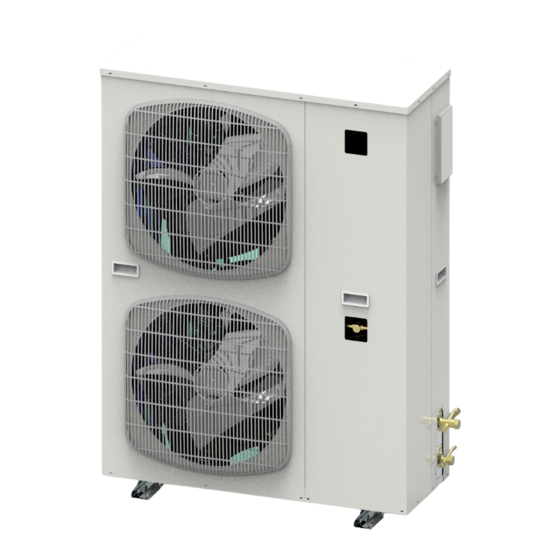
Page 7: Names Of Components
Names of Components Names of the Components Models : OCU-R200SF OCU-NR200SF OCU-R300SF OCU-NR200SF-D OCU-S350HF OCU-NR300SF OCU-S400HF OCU-NR300SF-D OCU-S400HF-D OCU-NS350HF OCU-S400SF OCU-NS400HF OCU-S400QSF OCU-NS400HF-D OCU-S350QSF-D OCU-NS350QSF-D Electric control Fan Cover cover Fan Blade Pressure Switch Sight Glass Suction line Service valve... - Page 8 Names of Components Names of Components Models: OCU-S500HF OCU-NS500HF OCU-S500HF-D OCU-NS500HF-D OCU-S600HF OCU-NS600HF OCU-S700HF OCU-NS700HF OCU-S500SF OCU-NS500SF OCU-S600SF OCU-NS600SF OCU-S500QSF OCU-NS500QSF OCU-S600QSF OCU-NS600QSF Electric control Fan Cover cover Pressure Switch Sight Glass Suction line Service valve Drier Filter Liquid Line Service Valve Compressor Service Valve...
- Page 9 MT Scroll Unit Rotor Unit Unit Unit Unit OCU-S350HF OCU-S400SF OCU-NS400SF OCU-NS350HF OCU-S400HF OCU-S500SF OCU-NS500SF OCU-NS400HF OCU-NR200SF-D OCU-S400HF-D OCU-S600SF OCU-NS600SF OCU-NS400HF-D Applicable OCU-R200SF OCU-NR300SF-D Unit OCU-S500HF OCU-S350QSF-D OCU-NS350QSF-D OCU-NS500HF OCU-R300SF OCU-NR200SF Model OCU-S500HF-D OCU-S400QSF OCU-NS400QSF OCU-NS500HF-D OCU-NR300SF OCU-S600HF OCU-S500QSF OCU-NS500QSF OCU-NS600HF...
- Page 10 Tips on the Effective Use of the Unit For Economical Use Following tips are the recommendations for the economical use of the condensing unit, for your reference. Cooling capacity greatly varies depending on application conditions. Cooling capacity decreases by 3 to 6% as evaporating temperature (temperature-conversion value of the pressure measured at the entrance to unit) drops by 1°C.
- Page 11 Tips on the Effective Use of the Unit Use with Specified Refrigerant The filter dryer in this unit will react with water and air, so please carefully observe following instructions. Never install this unit into a refrigeration system which is using different type refrigerant or oil. ( Only use this unit in a new system in case of the cleanliness, impurities and oil) .
-
Page 12: Selection Of Installation Location
Selection of Installation Location General precautions For the installation of the equipment, select a location where it is easy to do construction work and to perform daily operation and maintenance. ① ① As for distance between the equipment, select a place where the length of piping and wiring become as short as possible, and where it is easy to do construction work. -
Page 13: Examples Of Installation
Examples of Installation When there are no obstructions near the air outlet side and above air flow and above and above and above When there are obstructions near the air outlet side 2000mm and above 180mm and above (300+h) mm and above (850+h) mm and above Page... - Page 14 Examples of Installation Double Stack Installation Back to Back Installation 150mm and above 1000mm and above 180mm and above Face to face(Face to back) Installation 600mm 3500mm and above and above Page...
-
Page 15: Refrigerant Piping Work
Refrigerant Piping Work The quality of the design and construction work of refrigerant piping has great impact on the performance and reliability of Condensing unit. Observe precautions given below in the case of design and construction work. The compressor is cooled by liquid injection, if the refrigerant charge volume is not enough, the cooling effect will be decreased due to gas bubble in liquid line, it will result in high temperature of compressor. - Page 16 Refrigerant Piping Work When the evaporator is installed above the unit ● Difference in height shall be within 5 meters. Otherwise, flash gas may be caused by increased pressure loss Liquid prevent loop of a liquid refrigerant due to difference in height. Downward slope Evaporator...
-
Page 17: Refrigerant Oil
Technical Specification Ref. Oil Amount Ref. Oil Amount 压缩机头原冷 压缩机头原冷 Model Ref. Oil Ref. Ref. Oil Model 冷媒 机组型号 冷冻机油 机组型号 冷冻机油 冻油充填量L 冻油充填量L OCU-R200SF OCU-S350HF 3GSD-T OCU-R300SF OCU-S400HF OCU-S350QSF-D OCU-S400HF-D SAY-56T OCU-S400QSF OCU-S500HF R-22 OCU-S400SF OCU-S500HF-D 3GSD OCU-S500QSF OCU-S600HF OCU-S500SF... -
Page 18: Refrigerant Circuit Diagram
Refrigerant Circuit Diagram Models: OCU-R200SF OCU-NR200SF OCU-R300SF OCU-NR300SF Condenser Accumulator Fusible Plug Dryer Filter Sight Glass Liquid Injection Cooling Low pressure gas inlet pipe φ 15.9 Suction (Internal Welding) Accumulator High pressure liquid Pipe φ 15.9 Filter (Internal Welding) Customer oriented Models: OCU-NR200SF-D OCU-NR300SF-D... - Page 19 Refrigerant Circuit Diagram Models: OCU-S350HF OCU-S400HF OCU-S500HF OCU-S600HF OCU-S700HF Condenser Accumulator Fusible Plug Dryer Filter Sight Glass Liquid Injection Cooling Low pressure gas inlet pipe φ 19.05 (Internal Welding) High pressure liquid Pipe φ 9.52 Filter (Internal Welding) Customer oriented Models: OCU-NS350HF OCU-NS400HF OCU-NS500HF OCU-NS600HF OCU-NS700HF Condenser...
- Page 20 Refrigerant Circuit Diagram Models: OCU-S400HF-D OCU-S500HF-D Condenser Accumulator Fusible Plug Dryer Filter Sight Glass Liquid Injection Cooling Low pressure gas Suction inlet pipe φ 19.05 Accumulator (Internal Welding) High pressure liquid Pipe φ 9.52 Filter (Internal Welding) Customer Pressure-equalizing oriented solenoid valve Models: OCU-NS400HF-D OCU-NS500HF-D Condenser Accumulator Fusible Plug...
- Page 21 Refrigerant Circuit Diagram Models: OCU-S400SF OCU-NS400SF Condenser Accumulator Fusible Plug Dryer Filter Sight Glass Liquid Injection Cooling Suction Low pressure gas inlet pipe φ Accumulator 19.05(Internal Welding) High pressure liquid Pipe φ 9.52 Filter (Internal Welding) Customer oriented Models: OCU-S500SF OCU-NS500SF OCU-S600SF OCU-NS600SF Condenser Accumulator Fusible Plug Dryer Filter...
- Page 22 Refrigerant Circuit Diagram Models: OCU-S400QSF OCU-NS400QSF Condenser Accumulator Fusible Plug Dryer Filter Liquid Injection Cooling Sight Glass Low pressure gas inlet pipe Suction Accumulator φ 19.05(Internal High pressure liquid Pipe φ 9.52 Filter (Internal Welding) Customer oriented Models: OCU-S500QSF OCU-NS500QSF OCU-S600QSF OCU-NS600QSF Condenser Accumulator Fusible Plug Liquid Injection Dryer Filter...
- Page 23 Refrigerant Circuit Diagram Models: OCU-S350QSF-D OCU-NS350QSF-D Condenser Accumulator Fusible Plug Liquid Injection Dryer Filter Cooling Sight Glass Low pressure gas inlet pipe Suction φ 19.05(Internal Accumulator High pressure liquid Pipe φ 9.52 (Internal Welding) Filter Customer Pressure-equalizing oriented solenoid valve Page #...
-
Page 24: Refrigerant Charge
(8) An additional liquid tank may be installed if the refrigerant charge is too much for recovery. Standard Charge Volume Bubble Only Liquid Less refrigerant amount Proper refrigerant amount Volume of liquid receiver OCU-R200SF OCU-S400SF OCU-NR200SF OCU-NS400SF OCU-S600HF OCU-R300SF OCU-S500SF... -
Page 25: Electrical Wiring Work
Electrical Wiring Work Electrical work shall be done by qualified technicians with enough electrical knowledge. Ensure to install an earth leakage breaker with the designated capacity Use of an earth leakage breaker other than the one with designated capacity may disable the safety shutdown and cause electrical shock or fire. - Page 26 Electrical Wiring Project Wiring capacity of the unit is as followed: Power Line 电源线规格 Leakage protector or circuit Items Earthing Wiring 项目 漏电保护器※1 接地线 ※1 (mm )※2 breaker Rated leakage current Rated Current 额定电流 感度电流 Wire Diameter Within 30m 机组名称 30m以内 Model Names 线径(mm (mA) OCU-NR300SF...
- Page 27 Page...
- Page 30 This will cause damages to the stored items. Therefore, please take into consideration the setting up of alarm device and establishment of temperature management system at the planning period of project. Electrical Diagram Model: OCU-R200SF-D OCU-R300SF-D OCU-NR200SF-D OCU-NR300SF-D 第 页...
- Page 31 Electrical Wiring Project Electrical Diagram Models: OCU-S350QSF-D OCU-S400HF-D OCU-S500HF-D OCU-NS350QSF-D OCU-NS400HF-D OCU-NS500HF-D Page...
- Page 33 Electrical Wiring Project(续) Electrical Diagram Models: OCU-NR200SF OCU-R200SF OCU-S400SF OCU-NS400SF OCU-NR300SF OCU-R300SF OCU-S500SF OCU-NS500SF OCU-NS350HF OCU-S350HF OCU-S600SF OCU-NS600SF OCU-NS400HF OCU-S400HF OCU-S400QSF OCU-NS400QSF OCU-NS500HF OCU-S500HF OCU-S500QSF OCU-NS500QSF OCU-NS600HF OCU-S600HF OCU-S600QSF OCU-NS600QSF OCU-NS700HF OCU-S700HF Page #...
-
Page 34: Pcb Function
ON value of the pressure switch, the compressor will be started up in a delay time of 1 minute set by the factory. Delay time 1min 3min OCU-R200SF OCU-NR200SF OCU-S400HF-D OCU-S400SF OCU-NS400SF OCU-R300SF... - Page 35 Alarm code Fault Analysis Alarm Code Fault Analysis table Fault Code Table Fault Code Cause Method Anti-phase Protection Adjust the phase sequence Discharge Temp Abnormal Condenser Dirty Clean the condenser Confirm valve opening status one by one according to system Low charge quantity or refrigerant leakage diagram mprove ventilation conditions to ensure adequate ventilation...
- Page 36 Check Points and Settings for Operation Points to be confirmed before starting ⑴ ⑴ Reconfirm that there are no alarms or loosen connection in wiring. ⑵ ⑵ Open all the service valves to full extent with a ratchet wrench. ⑶ ⑶ Confirm that power-supply voltage falls within ±10% of rated voltage. ⑷...
- Page 37 Check Points and Settings for Operation Suction Superheat of Compressor Superheat = suction temperature of compressor - evaporation temperature of refrigerant in evaporator. With superheat, non refrigerant that enters into the compressor is in liquid state, which prevents the wet stroke. In order to avoid wet stroke, a certain degree of suction superheat is required to ensure that only dry steam enters the compressor (the presence of superheat indicates the complete evaporation of the liquid refrigerant due to the nature of the refrigerant).
-
Page 38: Maintenance
Maintenance The maintenance should be conducted by specialized technicians Some parts of the condensing unit are not for permanent use but for limited time. In order to prevent accidents, the regular maintenance and replacement of parts are required. We would like to ask you and customers to have a maintenance agreement and carry out regular maintenance of the equipment including the cooling system. -
Page 39: Troubleshooting Guide
Troubleshooting Guide When the unit fails to work or has a problem, please ask the specialized agency to repair. What to do in case of failure For some reasons, if the condensing unit or refrigerant circuit part fails to work, turn off the power before repairing. In order to avoid repeated failures, please pay attention to the following points (1)In order not to repeat the same failure, ensure to carry out the failure diagnosis and identify the broken part and its cause before repairing... - Page 40 Fault Analysis Fault Analysis Cause Method Fault Power source fault Measure power supply voltage, phase sequence, etc Replace the fuse Blown fuse Retest the controlled release loop current to confirm whether it is a control loop problem Check the air switch, confirm whether it is the electric type, check whether Air switch tripping there is leakage or short circuit in the power circuit, and repair it in time.
-
Page 41: Fault Analysis
Fault Analysis Fault Analysis Fault Cause Method The unit needs to be placed horizontally. Insufficient levelness of the unit High sound Loose anchor bolt of compressor The footing is fixed and strengthened again level of Supplement lubricating oil properly Poor lubrication running Contact with components in the case Adjust fasteners to avoid contact and collision... -
Page 42: Warranty Conditions
Warranty Conditions Warranty period and scope In the condition that customer strictly follows all instructions in this service manual, the warranty period is 18 (eighteen) months from the date of factory delivery.If the unit is found to be defective in material or workmanship, we will supply the free components or repair work to customers. -
Page 43: Warranty Terms
Warranty Terms Following failures are outside the scope of warranty (6) In the case of an accident or a breakdown caused by a power source failure; ● In the case of an accident caused by a motor or electrical component failure due to loss of phase or (open phase) with fuse short circuit or loose terminals of wires;... - Page 44 Customer Refrigeration Please fill in below table for convenient maintenance. Model Purchase Date Dealer Contact Tel( ) Production License Number:XK06-015-01985 Panasonic Appliances Refrigeration System (Dalian) Co., Ltd. Add.:No.8 Songlan Street,Economic & Technical Development Zone,Dalian City,P.R.China Tel:+86-400-886-1099 Fax:+86-411-39254255 P.C.:116600 E-mail:rsdlmarket@rsdl.panasonic.cn D00-2-L004-005-00-3 Web:http://rsdl.panasonic.cn...
- Page 45 MT and LT MT and LT Rotor MT and LT Scroll Items MT Scroll Unit Rotor Unit Unit Unit OCU-S350HF OCU-S400SF OCU-NR200SF- OCU-S400HF OCU-S500SF OCU- OCU-S400HF-D OCU-S600SF Applicable R200SF OCU-NR300SF- OCU-S500HF OCU-S350QSF-D Unit Model OCU- OCU-S500HF-D OCU-S400QSF R300SF OCU-NR200SF OCU-S600HF OCU-S500QSF OCU-NR300SF OCU-S700HF...
- Page 46 MT and LT Scroll MT Scroll Unit Unit OCU-NS400SF OCU-NS350HF OCU-NS500SF OCU-NS400HF OCU-NS600SF OCU-NS400HF-D OCU-NS350QSF- OCU-NS500HF OCU-NS500HF-D OCU-NS400QSF OCU-NS600HF OCU-NS500QSF OCU-NS700HF OCU-NS600QSF R404A -40~-5 -15~10 0.008~0.42 0.27~0.73 ture, the best suction superheat range is from de of unit) 30~55 1.33~2.78 ure+10K and over)...
- Page 49 MT Scroll Unit...
- Page 50 Meaning Alarm code Reverse phase or Loss of phase High pressure anomaly Over current (Constant speed operation) Discharge gas temperature anomaly (3rd trip) Discharge gas temperature sensor anomaly Low pressure sensor anomaly High pressure sensor anomaly Suction gas temperature sensor anomaly Discharge gas temperature anomaly (1st to 2nd trip) Inverter communication anomaly...
- Page 51 Cause § Detected reverse phase or loss of phase. § Condenser fan motor protection breaker (EB4) has been turned OFF. High pressure increased to 2.83MPa or higher and generated an abnormal stop. Thermal relay starts operating due to over current of the compressor.
- Page 52 Correction method (1) Check for the presence of any anomalies in the power supply. (2) Check the connection of the control PCB “3P3 connector (LINE PHASE)". (3) Check for the condenser fan motor protection breaker (EB4). (1) Investigate the cause of high pressure anomaly. (2) Check whether the high pressure sensor has failed.