
Related Manuals for Panasonic LP-RH Series


Summary of Contents for Panasonic LP-RH Series
- Page 1 Laser Marker Setup / Maintenance Guide LP-RH series Please read these instructions carefully before using this product, and save this manual for future use. ME-LPRH-SM-3 2024.2 panasonic.net/id/pidsx/global...
-
Page 2: Preface
Preface Thank you for purchasing our product. For full use of this product safely and properly, please read this document carefully. This product has been strictly checked and tested prior to its delivery. However, please make sure that this product operates properly before using it. -
Page 3: Cautions In Handling
Cautions in Handling ALWAYS FOLLOW THESE IMPORTANT SAFETY PRECAUTIONS! To reduce the risk of injury, loss of life, electric shock, fire, malfunction, and damage to equipment or property, always observe the following safety precautions. The following symbols are used to classify and describe the level of hazard, injury, and property damage caused when the denotation is disregarded and improper use is performed. - Page 4 WARNING • Do not use this product anywhere where fire is strictly prohibited, near inflammable gas, objects or organic solvents such as thinner or gasoline, or in dusty place. There is a risk of fire. • Do not use this product except for water-resistant part in wet place. In addition, never conduct wiring or maintenance work with wet hands or when the product surface is wet.
- Page 5 WARNING • Remove the dust and/or gas which may be generated during the laser radiation with dust collector or exhauster. Use an appropriate dust collector or exhauster for dust or gas generated. Depending on the material of the objects, harmful dust and/or gas to the human body and the laser marker may be generated.
- Page 6 • Do not touch the laser emission port on the bottom of the head. It may affect the marking quality badly. • Do not apply strong force to the LP-RH series head or front panel of the controller. When carrying if you hold the front panel, the panel may come off.
- Page 7 For the Proper Use of Product • Be sure to observe the following matters to prevent a failure or a malfunction of this product and to maintain the product performance properly. „ Wiring • Verify that the cables are wired correctly before powering on. •...
- Page 8 Network security As you will use this product connected to a network, your attention is called to the following security risks. (1) Leakage or theft of information through this product (2) Use of this product for illegal operations by persons with malicious intent (3) Interference with or stoppage of this unit by persons with malicious intent It is your responsibility to take precautions such as those described below to protect yourself against the above network security risks.
- Page 9 Products) as occasioned by the improvements of Products. Consequently, when you place orders for these Products, Panasonic Industrial Devices SUNX asks you to contact one of our customer service representatives and check that the details listed in the document are commensurate with the most up-to-date information.
-
Page 10: Related Regulations And Standards
*3 : UK Address: Panasonic UK, a branch of Panasonic Marketing Europe GmbH Maxis 2, Western Road, Bracknell, Berkshire, RG12 1RT *4 : The printed copy of UK declarations of conformity “UK Declaration of Incorporation of Partly Completed Machinery” is included in the package of this product. - Page 11 • Construct a safety system before using this product as it is a class 4 laser product. • While constructing the system, check ISO 13849-1 and ISO 11553-1, and take the required safety measures accordingly. Please see the “Laser Safety Guide” for details. „...
-
Page 12: Information For Use
Information for use „ Target readers This document is intended for the following readers: “System Designer” and “System Administrator” of the system that uses this product. Also, it is necessary to appoint a “Laser Safety Manager” in order to ensure safety regarding laser. Classification Description Laser Safety Manager... -
Page 13: How To Read This Document
In the text, multiple models may be described collectively, as shown in the table below. Please remind that the illustration and the screen image may vary with the model. Target model Description in the text LP-RH300S LP-RH Series LP-RH300T LP-RH301S LP-RH301T LP-RH305S... - Page 14 „ Type of manuals For this product, the following manuals are prepared. Read each manual and operate this product correctly and safely. Also, save the manuals for future use. Laser Safety Guide This manual describes the items required for using this product correctly and safely. All users shall be required for reading this manual.
-
Page 15: Table Of Contents
Contents Preface ....................... 2 Cautions in Handling ................... 3 Related Regulations and Standards ..............10 Information for use ..................... 12 How to Read this Document ................13 1 Product Overview …………………………………………………… 19 1-1 Product Model ..................... 20 1-2 Product Configuration ................. 21 1-2-1 Basic composition .................. - Page 16 2-6-2 Power connection and earth (Grounding) ..........60 2-6-3 Restore of circuit protector ................ 62 2-6-4 Connection of PC (Laser marker NAVI smart) .......... 63 2-6-5 Connection of Console ................65 2-6-6 Connection of Monitor and Mouse ............66 2-7 Construction of System ................67 3 Operation Method……………………………………………………...
- Page 17 4-6-3 Marking trigger input (to static object): Single trigger ....... 120 4-6-4 Marking trigger input: Continuous trigger ..........121 4-6-5 On-the-fly marking: Single trigger ............123 4-6-6 On-the-fly marking: Marking at regular intervals ........124 4-6-7 On-the-fly marking: Multiple triggers ............125 4-6-8 On-the-fly marking: 2 sensors input ............
- Page 18 6-2-3 Connection ....................168 6-2-4 Preparation of readout code ..............169 6-2-5 Setting of code reader linkage functions ...........170 7 Maintenance ……………………………………………………… 172 7-1 Maintenance Items ..................173 7-2 Maintenance Details of Parts ..............174 7-2-1 Laser emission port (f θ lens) ..............174 7-2-2 Intake/exhaust vent ..................176 7-2-3 Air filter ......................
-
Page 19: Product Overview
1 Product Overview ME-LPRH-SM-3... -
Page 20: Product Model
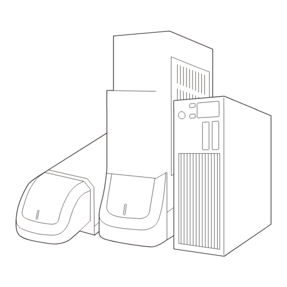
Tower „ Model description LP-RH 300 S Represents the series name. “LP-RH series” refers to the CO2 laser marker. Represents the laser output class. The following types are applicable to this product. Laser oscillator average output 30W Laser oscillator average output 20W Laser oscillator average output 10W Represents the marking field size. -
Page 21: Product Configuration
1-2 Product Configuration 1-2-1 Basic composition This product is a laser marker designed to mark and process the object by radiating a laser beam to the target. The laser marker LP-RH series consists of the following units mainly. Name Description Head It is the unit that radiates the laser beam. -
Page 22: Optional Items
1-2-2 Optional items The following optional items (sold separately) are available for this product. For purchasing and the detailed information, please contact our sales office. Option items Model AC power cable: Rating 125V AC, PSE certified cable (For Japan) LP-ACA10 AC power cable: Rating 250V AC, PSE certified cable (For Japan) LP-ACA11 AC power cable: Rating 250V AC, CE certified cable (For Europe) *1... -
Page 23: Package
1-2-3 Package Before using this product, be sure to check the packed objects. This product is packaged in one box with head and one box with controller. Though the package has been checked prior to the delivery, if you find any missing item, please contact the dealer you purchased from or our sales office. - Page 24 „ Laser marker controller □ Laser marker controller 1 unit □ System key □ Unit power cable □ Signal cable (5m) □ I/O connector (5m) qty.: 2 qty.: 1 qty.: 1 qty.: 1 □ I/O terminal block □ Jumper wire □...
-
Page 25: Download Software And Manual
1-2-4 Download software and manual „ Download Laser Marker Smart Utility Please download “Laser Marker Smart Utility” for the drivers, software and manuals of LP-RH series from our Internet website before use. Decompress the downloaded file and install the software to your PC. -
Page 26: Specification
1-3 Specification „ Optical specifications / Scanning specification Model Item LP-RH300S LP-RH200S LP-RH100S LP-RH301S LP-RH101S LP-RH305S LP-RH300T LP-RH200T LP-RH100T LP-RH301T LP-RH101T LP-RH305T Scanning system Galvano scanning method Marking field (X, 110mm x 110mm 55mm x 55mm 160mm x 160mm Work distance *1 185mm 111mm 262mm... - Page 27 Model Item LP-RH300S LP-RH200S LP-RH100S LP-RH301S LP-RH101S LP-RH305S LP-RH300T LP-RH200T LP-RH100T LP-RH301T LP-RH101T LP-RH305T West-European alphabet (A to Z, a to z, Latin-1 characters), numeric, symbol, user defined characters (up to 50 characters can be set) Character Japanese characters: Katakana, Hiragana, Kanji (JIS level-1 and level-2) Simplified Chinese characters: GB 2312 level-1 and level-2 TrueType TrueType fonts stored in the PC with Laser Marker NAVI smart installed *5...
- Page 28 Model Item LP-RH300S LP-RH200S LP-RH100S LP-RH301S LP-RH101S LP-RH305S LP-RH300T LP-RH200T LP-RH100T LP-RH301T LP-RH101T LP-RH305T Pollution degree Use location Indoor; at an altitude of 1000 m or below Head In all directions Installation direction Controller Vertically or horizontally Approx. Approx. Approx. Approx.
-
Page 29: Outer Dimensional Drawing
1-4 Outer Dimensional Drawing 1-4-1 Head „ Standard head model LP-RH300S / LP-RH200S / LP-RH100S / LP-RH301S / LP-RH101S / LP-RH305S Unit: mm (20) (148) (60) (13) (Φ7) (117) (16) (333) (119) (200) (51) Φ94 Description Work distance: LP-RH300S / LP-RH200S / LP-RH100S : 185mm LP-RH301S / LP-RH101S : 111mm LP-RH305S : 262mm Center of marking field... - Page 30 „ Tower head model LP-RH300T / LP-RH200T / LP-RH100T / LP-RH301T / LP-RH101T / LP-RH305T Unit: mm (43) (142) (20) (76) (30) 55 90 30.5 (38) Enlarged drawing of B 30.5 φ94 (182) 170.5 Enlarged drawing of C Description Work distance: LP-RH300T/ LP-RH200T / LP-RH100T : 185mm LP-RH301T / LP-RH101T : 111mm LP-RH305T : 262mm...
-
Page 31: Controller
1-4-2 Controller Unit: mm (23.5) (161) Description Controller fixing screw hole (4 holes each on the bottom and left side facing the front): M5 screw, depth 6 Screw for protective conductor terminal: M4 screw, screw hole depth 5 ME-LPRH-SM-3... -
Page 32: Cables
1-4-3 Cables „ Unit power cable Unit: mm Minimum bent radius 100mm +200 5000 0 „ Signal cable Unit: mm Minimum bent radius 100mm +200 5000 0 „ AC power cable: Optional item on request The AC power cable is not included in this product. Use the specified optional cable or a cable with the enough rating capacity to fulfil the power voltage specification of this product, which is compliant with the regulations and standards in the country or region where it is used. -
Page 33: Touch Panel Console
1-4-4 Touch panel console This product can use the touch panel console LP-ADP50 (sold separately) as a monitor during operation. Touch panel console is available when the optional expansion board is installed to the controller. Model: LP-ADP50 Weight: Approx. 1.5kg Unit: mm (265) (36) -
Page 34: Name Of Each Component
1-5 Name of Each Component 1-5-1 Head „ Standard model LP-RH300S / LP-RH200S / LP-RH100S / LP-RH301S / LP-RH101S / LP-RH305S 9 10 „ Tower head model LP-RH300T / LP-RH200T / LP-RH100T / LP-RH301T / LP-RH101T / LP-RH305T ME-LPRH-SM-3... - Page 35 Laser radiation indicator The display that shows the status of laser radiation and the laser marker. Laser marker status Head LED status Being in laser emitting Orange lighted-up Laser pumping is completed and internal shutter opened Green lighted-up Laser pumping is completed and internal shutter closed White lighted-up Laser pumping is in progress (uncompleted) and internal shutter opened Green flashing...
- Page 36 10. Arrow for Indicating Rotation Angle [Only for the standard head] This is the arrow that indicates rotation angle of the head scanner. For the details, refer to “2-3-3 Rotation of Standard Head Scanner” (P.48). ME-LPRH-SM-3...
-
Page 37: Controller
1-5-2 Controller „ Front Key switch: POWER The main power switch for the laser marker. Turn ON ( | ) the key switch to start-up the system, and turn OFF ( ○ ) to shut down the system. Only when the key switch is turned OFF (in O position), the key can be pulled out. When the laser marker is not in use, the key should be in safekeeping by a laser safety officer. - Page 38 Circuit protector: CIRCUIT PROTECTOR In case of the overcurrent, one or both circuit protectors pop out and cutoff current. Refer to “2-6-3 Restore of circuit protector” (P.62). USB port B: USB This is the connector for connecting the attached USB cable. When you connect the laser marker configuration software Laser Marker NAVI smart online, connect this cable to the PC.
- Page 39 „ Rear Power connector: POWER This is the connector for supplying the power to the head. Connect the attached unit power cable. • For the connecting details, refer to “2-6-1 Connection of head and controller” (P.59). Ethernet port: LAN The port to connect the LAN cable used when connecting the laser marker with the following devices via Ethernet. •...
- Page 40 Ports for industrial network: EtherNet/IP or PROFINET *1 The ports for the optional network unit (EtherNet/IP unit or PROFINET unit). Communication port (2-port switch) to control the laser marker by the industrial network with the control device such as a PLC. Connect a LAN cable.
- Page 41 14. Protective conductor terminal The terminal for ground. Connect this terminal to grounding port permanently. 15. Clamp The clamp to fix the AC power cable. 16. Controller air-cooling outlet The air-cooling outlet for the controller. *1: This port is equipped when the optional network unit (EtherNet/IP unit, PROFINET unit) is installed. *2: This port is equipped when the optional expansion board is installed.
-
Page 42: Laser Marker Installation
2 Laser Marker Installation ME-LPRH-SM-3... -
Page 43: Installation Environment
2-1 Installation Environment Use this product in the following environments. Item Installation environment conditions Operating ambient temperature *1 0°C to +40°C Operating ambient humidity *1 35 to 85%RH Ambient temperature for storage *1 -10°C to +60°C *2 Pollution degree Use location Indoor;... -
Page 44: Installation Space
2-2 Installation Space To keep the appropriate air cooling performance, provide space around the laser marker as shown in the following figure. • To maintain the air-cooling performance of the laser marker, install the head and controller in a well-ventilated place respectively. -
Page 45: Head Installation
2-3 Head Installation • Make sure that the power is turned OFF at installing. Failure to do so may cause electrical shock. WARNING • Install the product so that the laser beam path does not cross the eye height. • The laser beam path shall be enclosed with protective enclosure and make sure it is not exposed with direct light or reflected light. - Page 46 „ Tower head model When the mounting surface of the tower head is rear side, it can be mounted in the left, right, top and bottom direction. When the lens side is mounting surface, install the tower head always with the lens side down. •...
-
Page 47: Installation Method
2-3-2 Installation method • Install the head on a plate with a thickness of 10 mm to 15 mm which is made of aluminum or other material with radiation performance equivalent to that of aluminum. • For details of installation, refer to “1-4-1 Head” (P.29). •... -
Page 48: Rotation Of Standard Head Scanner
2-3-3 Rotation of Standard Head Scanner For the standard head models (LP-RH300S / LP-RH200S / LP-RH100S / LP-RH301S / LP-RH101S / LP-RH305S), the angle of the head scanner unit can be set freely. This function is specific to the standard head model. It is not equipped in the tower head model. „... -
Page 49: Marking Field And Marking Center Position
2-3-4 Marking field and marking center position LP-RH300S LP-RH300T LP-RH301S LP-RH301T Specified point LP-RH200S LP-RH200T LP-RH305S LP-RH305T LP-RH101S LP-RH101T LP-RH100S LP-RH100T Distance to center of 113mm 170.5mm 113mm 170.5mm 113mm 170.5mm marking field Marking field (X, Y) 110×110mm 55×55mm 160×160mm Work distance 185mm 111mm... -
Page 50: Marking Position Check
2-3-5 Marking position check „ Guide laser The marking position can be checked visually by using the guide function with the red laser beam. • Use the guide display function only as the guideline. For the appropriate marking quality, fine adjust the work distance and setting position of the target object by checking the actual marking results. -
Page 51: Focus Adjustment Function
2-3-6 Focus adjustment function With this function, the distance from work (focal length) can be adjusted without moving up/down the head. Marking energy density can be reduced by moving the focus point of the laser spot with the specified distance between the works and changing the spot diameter. - Page 52 Reinstall the focus adjustment cover. Tightening torque for the cover should be 0.65 to 0.75 N • m. • Focus adjustment range varies depending on models. • LP-RH300S / LP-RH300T / LP-RH200S / LP-RH200T / LP-RH100S / LP-RH100T: Approx. ± 3 mm •...
-
Page 53: Marking Check
2-3-7 Marking check Due to the characteristics of the laser marker, the laser output, focus (work distance), and marking state may vary depending on the temperature environment or operating conditions. Take the following measures to obtain stable results. • Before full operation, perform test marking to make sure that there is leeway in terms of the marking conditions and also marking performance is stable. -
Page 54: Controller Installation
2-4 Controller Installation • Make sure that the power is turned OFF at installing. Failure to do so may cause electrical shock. WARNING • To carry this product, wear the non-slip gloves. • In case it falls down, it may cause injury. 2-4-1 Installation method „... -
Page 55: Expansion Board Installation
2-5 Expansion board installation This section describes the procedure for installing the expansion board to the laser marker controller. When the expansion board is installed to the controller, the following functions can be used. • Connect a console or a commercially available monitor to the laser marker and use it for monitoring and setting during operation. - Page 56 Loosen four M3 screws fixing the plate at the location, to which the expansion board is installed, and remove the circuit board from the controller. Remove the protection cap from the connector located under the removed plate. Install the expansion board to the location shown in the figure. Insert the connector on the back of the board into the connector of the laser marker and tighten the four M3 screws removed earlier into screw holes in four corners of the board.
- Page 57 Not available 3.1.05 3.2.03 Not available 3.2.03 3.1.06 Available 3.2.03 3.2.04 Update the firmware in the controller and expansion board. The software for updating the LP-RH/LP-ZV series, Laser Marker Firmware Updater, can be downloaded from the following website: https://www3.panasonic.biz/ac/e/fasys/software_info/lasermarker/tol_lp-zv_firm.jsp ME-LPRH-SM-3...
- Page 58 The software for updating the LP-RH/LP-ZV series, Laser Marker Firmware Updater, can be downloaded from the following website: https://www3.panasonic.biz/ac/e/fasys/software_info/ lasermarker/tol_lp-zv_firm.jsp • Install the expansion board LP-AEB10 to the controller LP-RH/LP-ZV before performing the firmware updates. • The firmware of both controller and expansion board will be updated to the versions bound in Laser Marker Firmware Updater.
-
Page 59: Connecting Laser Marker
2-6 Connecting Laser Marker • Be sure to turn the power off before you conduct wiring or connection. Failure to do so may cause electrical shock. WARNING • Be sure to connect the head and controller of the laser marker with the correct combination of models. -
Page 60: Power Connection And Earth (Grounding)
2-6-2 Power connection and earth (Grounding) When connecting the power supply, be sure to perform earth (grounding) properly. Failure to do so may cause electrical shock in case of a failure or electrical leakage. Further, it may cause malfunction of the device. The power supply terminal, protective conductor terminal and frame ground terminal are located as indicated below. - Page 61 Connect the three wires to the terminals. The signs of “L (black)”, “N (white)” and “PE (GND) (yellow/green)” show in the cables. Connect each cable to the appropriate terminal. Screw size: M4 Tightening torque: 1.8N·m • For the AC power supply cable, use the specified optional AC power cable or a cable with the enough rating capacity to fulfil the power voltage specification of this product.
-
Page 62: Restore Of Circuit Protector
2-6-3 Restore of circuit protector Two circuit protectors are mounted in front of the controller for the overcurrent protection. In case of the overcurrent, One or both circuit protectors pop out and cutoff current. To recover the power supply of the laser marker, turn ON the switch of the circuit protector with the following procedures. Remove causes of the overcurrent. -
Page 63: Connection Of Pc (Laser Marker Navi Smart)
2-6-4 Connection of PC (Laser marker NAVI smart) This product is set and operated with the PC with the PC configuration software “Laser Marker NAVI smart” installed and the laser marker connected. „ Installation of laser marker NAVI smart • “Laser Marker Smart Utility” that contains the software including Laser Marker NAVI smart and PDF manuals is available from our Internet website. - Page 64 „ Connection type With one of the following methods you can connect a PC with Laser Marker NAVI smart installed and the laser marker. • One PC can be connected with multiple laser markers. However, only one laser marker can be connected with Laser Marker NAVI smart online.
-
Page 65: Connection Of Console
2-6-5 Connection of Console This product can be used for monitoring and setting during operation by connecting the touch panel console LP-ADP50 (sold separately). Touch panel console is available when the optional expansion board is installed to the controller. Refer to “2-5 Expansion board installation”... -
Page 66: Connection Of Monitor And Mouse
2-6-6 Connection of Monitor and Mouse This product can be used for monitoring and setting during operation by connecting a commercially available monitor and mouse. The monitor and mouse are available when the optional expansion board is installed to the controller. Refer to “2-5 Expansion board installation”... -
Page 67: Construction Of System
2-7 Construction of System The following figure shows the construction sample of the system. Description Installation and control sample Laser marker head Laser marker controller PC for laser marker setting/monitoring Protective enclosure Laser protection shutter for workpiece Construct a control system which will separate (cut off) the laser beams gateway or shut off the laser power when it is opened. -
Page 68: Operation Method
3 Operation Method ME-LPRH-SM-3... -
Page 69: Type Of Operations
3-1 Type of Operations The laser marker can be controlled by the following method: Control by the PC configuration software “Laser Marker NAVI smart” Establish an online connection of the laser marker and Laser Marker NAVI smart (PC). You can control the operations such as laser pumping or marking on the Laser Marker NAVI smart screen. -
Page 70: Start-Up & Termination
To configure and control by the PC configuration software, start Laser Marker NAVI smart and establish an online connection with the laser marker. • In Windows 11, open the start menu and select “All Apps” - “Panasonic-ID SUNX Laser” - “Laser Marker NAVI smart”. -
Page 71: Termination Procedure
3-2-2 Termination procedure Turn OFF the laser pumping. “Laser pumping” tool • PC configuration software control: Click “Laser pumping” on the ribbon to turn off the laser pumping. • Remote control: Turn off the laser pumping by LASER SUPPLY IN (X6) of I/O terminal or by the laser pumping command (LSR). ON status OFF status Overwrite the data as needed. -
Page 72: Operation By Pc Configuration Software
3-3 Operation by PC Configuration Software You can configure the following settings and operations with Laser Marker NAVI smart respectively when the laser marker is not connected (offline) and when the laser marker is connected (online). „ Offline editing The followings are supported in the offline editing. •... - Page 73 „ Online connection: Operation example from editing to marking Turn on the key switch of the laser marking system. Start up Laser Marker NAVI smart. For test marking For RUN mode Select “Online”. Select the laser marking system to connect. Select a file to edit in the “Marking settings”...
-
Page 74: Screen Types
3-3-2 Screen types Laser Marker NAVI smart has the different screen mode depending on the settings and operation contents. The availability of screens depends on the application mode and the user role (administrator or restricted user) as follows: • In online mode, the user is “Administrator”: “Startup”, “Marking settings”, “Monitor”, “Maintenance”, “Data management”, “System settings”... - Page 75 „ Maintenance This screen is used for the maintenance of the laser marking system. Main usages: • Check the operating data. • Measure the laser output using a power meter available in stores. • Simulate ON/OFF operation of the output signals •...
-
Page 76: How To Establish Online Connection
3-3-3 How to establish online connection Connect the laser marker and the PC with a USB cable. Start the laser marker. Start the Laser Marker NAVI smart. The startup screen appears. On the “Startup” screen, select “Online” to open the “Connection” dialog. Any laser marking system that is ready for an online connection is displayed in the list. - Page 77 „ Setting procedure for Ethernet online connection For communication between the laser marker and PC terminal using Ethernet, you need to configure the following communication settings first. Connect Laser Marker NAVI smart and laser marker to online via a USB cable. Go to the “System settings”...
-
Page 78: How To Disconnect Online Connection
3-3-4 How to disconnect online connection • Disconnect the online connection before turning the laser marker power OFF. Select the “Connection” tool in the ribbon or go to the “Startup” screen and select “Online”. “Connection” tool In the “Connection” dialog, select “Disconnect”. The online connection with the laser marking system is now disconnected. -
Page 79: User Selection And Password Settings
3-3-5 User selection and password settings In online mode, you can select between two user roles “Restricted user” or “Administrator”. If you have configured the password on the “System settings” screen, you are required to enter the password when you log in as an “Administrator”. - Page 80 If you specify the installation destination of Laser Marker NAVI Smart Utility to the default folder, you can find “ClearPassword.exe” at the following location. C:\Program Files (x86)\Panasonic-ID SUNX Laser\Laser Marker Smart Utility\Tools\ClearPassword\ClearPassword. C:\ProgramFiles\Panasonic-IDSUNXLaser\LaserMarkerSmartUtility\Tools\ClearPassword\ClearPassword.exe • During the “ClearPassword.exe” running, it does not matter whether the laser marker and PC are connected or not.
- Page 81 Start Laser Marker NAVI smart and establish an online connection with the laser marker of which password setting you want to delete. This deletes the password, and the password will not be required to log in as an administrator. Exit from the Laser Marker NAVI smart. Execute ClearPassword.exe again.
-
Page 82: Test Marking And Run Mode
3-3-6 Test marking and RUN mode When you execute marking using the PC configuration software control, the laser irradiates in the following methods: „ Test marking procedure Test marking is a marking method of radiating laser by the operations on the Laser Marker NAVI smart. Establish an online connection between your PC and the laser marking system and go to the “Marking settings”... - Page 83 „ RUN mode procedure In RUN mode, either a signal from Laser Marker NAVI smart or from an external device starts the laser radiation. Establish an online connection between your PC and the laser marking system. Select “Laser pumping” in the ribbon to turn on the laser pumping. “Laser pumping”...
-
Page 84: Operation By External Devices
3-4 Operation by External Devices 3-4-1 Operation method using external control device To control the laser marker with the external control device, the following connecting methods are applicable: Control by I/O (remote mode) Controls the laser marker from external devices such as PLC using I/O signals loaded into the laser marker. For details, refer to “4 External Control Using I/O”... -
Page 85: Operation Procedure With External Control
3-4-2 Operation procedure with external control ⿎ Operation example when controlling the laser marker from external control devices such as Turn ON key switch of laser marker controller Remote mode ON Refer to “3-4-4 Remote mode settings” (P.89). Control by communication I/O control commands Select file... -
Page 86: General Settings Before External Control
3-4-3 General settings before external control To control the laser marker via I/O or communication commands, configure the following items in advance at the system settings of Laser Marker NAVI smart. Establish an online connection between your PC and the laser marking system. Go to the “System settings”... - Page 87 When using I/O, click the “Inputs/outputs” tab and configure the following items: • One-shot pulse duration: Configure the output time of the signal being output as one-shot, such as PROCESSING END OUT (Y11). Setting range: 2 to 510ms (initial value is 40ms) •...
- Page 88 Under “Command format”, specify the communication command format. • Start code: STX (initial setting) / None • Include command in response: ON (initial setting) / OFF • Sub-command for response data: Any single byte character of ASCII code from 01(HEX) to 7F(HEX) can be specified.
-
Page 89: Remote Mode Settings
3-4-4 Remote mode settings To control the laser marker externally via I/O or communication commands, set the operation mode to the remote mode with one of the following methods. Select the method to switch to the remote mode on the system settings screen of Laser Marker NAVI smart. Refer to “3-4-3 General settings before external control”... -
Page 90: External Control Using I/O
4 External Control Using I/O ME-LPRH-SM-3... -
Page 91: I/O Interface Specification
4-1 I/O Interface Specification The I/O terminal block and the I/O connector are available as the external control I/O interface of this product. • I/O terminal block: Loaded with the basic input/output to control the laser marker. • I/O connector: Loaded with the input/output for data configuration such as selecting a file number and the input/output for the specific functions. -
Page 92: Signals And Details Of I/O Terminal Block
4-2 Signals and Details of I/O Terminal Block The I/O terminal block is loaded with the basic input/output to control the laser marker. „ List of signals Name Name 24V OUT 0V OUT Internal power 24V Internal power 0V IN COM. 1 OUT COM. - Page 93 „ Input signal operation on the I/O terminal block • The ON/OFF listed in this section refers to the ON/OFF operations. It does not refer to the voltage level (High/Low). Name and description 24V OUT: Internal power (power for input/output) + 24V DC (max. output current 300mA) Power to operate the laser marker independently.
- Page 94 Name and description • You can set the trigger mode with Laser Marker NAVI smart. For the marking to static object, it is specified in “File settings” by each file. For on-the-fly marking, it is specified in “Motion settings to all files” and this one setting is applied to all files.
- Page 95 Name and description LASER STOP IN LASER STOP IN Use these terminals when you want to stop the laser radiation or disable the laser radiation temporarily. When between LASER STOP IN and OUT COM. 1 is disconnected, the laser radiation will be disabled. The laser marker operation varies depending on its condition as shown below.
- Page 96 Name and description INTERLOCK 1(+) INTERLOCK 1(-) INTERLOCK 2(+) INTERLOCK 2(-) The terminal used as the interlock, which is connected to the door or switches of the safety device. When the connection between INTERLOCK (+) and INTERLOCK (-) is opened, the shutter is closed and the laser pumping is turned OFF physically.
- Page 97 „ Output signal operation on the I/O terminal block • The ON/OFF listed in this section refers to the ON/OFF operations. It does not refer to the voltage level (High/Low). Name and description 0V OUT: Internal power (power supply for input/output) 0V Power to operate the laser marker independently.
- Page 98 Name and description SHUTTER CLOSE 1 OUT SHUTTER CLOSE 2 OUT Output ON during internal shutter of the head is closed. The sensor mounted inside of the head detect the shutter status and output them as SHUTTER CLOSE 1 OUT and SHUTTER CLOSE 2 OUT respectively. SHUTTER CLOSE 1 OUT and SHUTTER CLOSE 2 OUT are the same internal shutter sensor output.
- Page 99 Name and description INTERLOCK 1 MONITOR: Interlock 1 monitoring INTERLOCK 1 MONITOR COM.: Interlock 1 monitoring common INTERLOCK 2 MONITOR: Interlock 2 monitoring INTERLOCK 2 MONITOR COM.: Interlock 2 monitoring common INTERLOCK 1 MONITOR (Y16 - Y17) monitors the contact status of INTERLOCK 1 (X16 - X17). INTERLOCK 2 MONITOR (Y18 - Y19) monitors the contact status of INTERLOCK 2 (X18 - X19).
- Page 100 „ Laser marker operation when functions for safety measures are input If INTERLOCK (X16, X17, X18, X19) or REMOTE INTERLOCK IN (X20) is opened, regardless laser emission ON/OFF status, the laser is powered OFF and the shutter is closed. The operation behavior of LASER STOP IN (X10, X11) varies depending on the laser emission ON/OFF status. Safety function Laser marker operation Release method...
-
Page 101: Signals And Details Of I/O Connector
4-3 Signals and Details of I/O Connector The I/O connector is loaded with the input/output for data setting such as selecting a number and the input/output for the specific functions. „ List of signals Name Name IN COM. 2 OUT COM. 2 Input common 2 Output common 2 SET IN... - Page 102 „ Input signal operation on the I/O connector • The ON/OFF listed in this section refers to the ON/OFF operations. It does not refer to the voltage level (High/Low). Name and description IN COM. 2: Input common 2 The common terminal for each input of the I/O connector. For NPN connection, this terminal is connected to the “+ (plus)”...
- Page 103 Name and description Count-up value correction (SELECT 1 IN: ON) Count-down value correction (SELECT 0 IN, SELECT 1 IN: ON) Input this number when you change the next marking value of the counter function. The counter value is specified by the step times of count-up or count-down. The step value indicates a value to increase or decrease per one counting-up or counting-down.
- Page 104 Name and description Data number to switch when using the registered characters/external offset function (SELECT 0 IN: ON) The registered characters/external offset function is a function that switches marking characters (registered characters) or the position (external offset) using the input terminal D0 to D15. Configure the character or coordinate patterns to the data number corresponding to D0 to D15 in advance.
- Page 105 Name and description 19 to 21 SELECT 0 IN to SELECT 2 IN With SELECT 0 IN to SELECT 2 IN, the setting target of D0 IN to D15 IN and Guide laser indication target are specified. • Select the setting target of D0 IN to D15 IN Specify SELECT 0 IN to SELECT 2 IN corresponding to the setting target shown below.
- Page 106 „ I/O connector output signal operation • The ON/OFF listed in this section refers to the ON/OFF operations. It does not refer to the voltage level (High/Low). Name and description OUT COM. 2: Output common 2 The common terminal for each output of the I/O connector. For NPN connection, this terminal is connected to the “- (minus)”...
- Page 107 Name and description CHECK OK OUT: Check OK output CHECK NG OUT: Check NG output • These outputs are available when the following functions are configured. This is One-shot output. *1 • When the link control function with the image checker is configured: Check results by the linked image checker, such as a camera or a code reader are output.
- Page 108 Name and description LASING OUT: Laser radiation output Output ON during laser radiation. In case the lasing time is shorter than the set one-shot output time, the lasing output remains ON until the one-shot output time ends. *1 • Use PROCESSING END OUT (Y11) and PROCESSING FAIL OUT (Y12) for the confirmation of marking completion.
-
Page 109: I/O Rating/Circuit
4-4 I/O Rating/Circuit 4-4-1 Input rating and input circuit This section shows the input rating and the input circuit for the I/O terminal block input and the I/O connector input. Note that the input rating and circuit of INTERLOCK terminals (X16, X17, X18, X19) are different from those shown here. Refer to “4-4-3 Interlock terminal rating and I/O circuit”... -
Page 110: Output Rating And Output Circuit
4-4-2 Output rating and output circuit This section shows the output rating and the output circuit for the I/O terminal block output and the I/O connector output. Note that the output rating and circuit of INTERLOCK MONITOR terminals (Y16, Y17, Y18, Y19) are different from those shown here. -
Page 111: Interlock Terminal Rating And I/O Circuit
4-4-3 Interlock terminal rating and I/O circuit This section shows the following interlock terminals and I/O circuit loaded onto the I/O terminal block. Interlock input terminals: Interlock monitoring terminals: INTERLOCK 1(+) (X16) INTERLOCK 1 MONITOR (Y16) INTERLOCK 1(-) (X17) INTERLOCK 1 MONITOR COM. (Y17) INTERLOCK 2(+) (X18) INTERLOCK 2 MONITOR (Y18) INTERLOCK 2(-) (X19) -
Page 112: Connecting I/O Terminal Block
4-5 Connecting I/O Terminal Block WARNING • Make sure that the power is turned OFF at wiring. 4-5-1 Factory default wiring The following terminals are connected by jumper wires at the factory default. Remove these jumper wires when you connect them to an external device. 24V OUT 0V OUT IN COM. -
Page 113: Connecting Common Terminals
4-5-2 Connecting common terminals Connect IN COM. 1 (X2) and OUT COM. 1 (Y2) respectively to the power supply for input and output. For the I/O connector terminals, connect IN COM. 2 and OUT COM. 2 respectively to the power supply in the same manner. -
Page 114: Sensor Connection Example
4-5-3 Sensor connection example „ Use the sensor as a marking trigger (operate the sensor by the internal power) NPN connection PNP connection Sensor Sensor 24V OUT 24V OUT 0V OUT OUT COM. 1 IN COM. 1 IN COM. 1 OUT COM. -
Page 115: Checking The I/O Terminal Status
4-5-5 Checking the I/O terminal status Check the I/O connection status and its operation using the functions in the PC configuration software “Laser Marker NAVI smart” Operation procedure. „ I/O monitor I/O monitor indicates ON/OFF status of the I/O terminals on the laser marker. Open the I/O monitor with the following procedure. - Page 116 „ Output simulation With the output simulation you can check the output signals of the laser marker without an actual operation. Use this function to confirm the operation of the external devices connected with the laser marker. Output simulation starts with the following procedure. Establish an online connection between your PC and the laser marking system.
-
Page 117: Basic Control Timing Chart
4-6 Basic Control Timing Chart • ON/OFF on the timing chart refers to ON/OFF operations. It does not refer to the voltage level (High/Low). • In the following timing charts, the timing of output operation corresponding to each input has a small delay of 0ms or more. - Page 118 Item Time Remarks Approx. 10 sec. Time for system startup. Turn ON the remote mode upon verifying SYSTEM STANDBY OUT (Y7). Approx. 5 sec. Time for completion of laser pumping. • At the usual operation: Approx. 5 sec. • Re-pumping right after turning the laser pumping OFF: Max. 10 sec. Max.
-
Page 119: Shutter Open/Close
4-6-2 Shutter open/close LASER SUPPLY IN (X6) TRIGGER IN (X5) SHUTTER ENABLE IN (X9) ON (Open) SHUTTER IN (X8) OFF (Close) ON (Close) SHUTTER CLOSE 1 OUT (Y8) OFF (Open) ON (Close) SHUTTER CLOSE 2 OUT (Y9) OFF (Open) ON (Open) SHUTTER OPEN OUT (No.39) OFF (Close) -
Page 120: Marking Trigger Input (To Static Object): Single Trigger
4-6-3 Marking trigger input (to static object): Single trigger When the trigger mode is set to “single trigger” in the file settings, one lasing operation is executed by the edge of turning on of TRIGGER IN (X5). READY OUT (Y5) TRIGGER IN (X5) Marking interruption... -
Page 121: Marking Trigger Input: Continuous Trigger
4-6-4 Marking trigger input: Continuous trigger „ Without “allow to stop halfway” setting When the trigger mode is set to “continuous trigger” in the file settings, lasing operation is repeated while TRIGGER IN (X5) is on. Without “allow to stop halfway” setting if TRIGGER IN turns OFF when the lasing operation is running, the lasing operation is terminated after finishing the running operation. - Page 122 „ With “allow to stop halfway” setting When the trigger mode is set to “continuous trigger” in the file settings, lasing operation is repeated while TRIGGER IN (X5) is on. With “allow to stop halfway” setting, the lasing operation is terminated immediately when TRIGGER IN turns OFF. READY OUT (Y5) TRIGGER IN (X5) Marking...
-
Page 123: On-The-Fly Marking: Single Trigger
4-6-5 On-the-fly marking: Single trigger ON (Open) SHUTTER OPEN OUT (No.39) OFF (Close) READY OUT (Y5) TRIGGER IN (X5) PROCESSING OUT (Y10) LASING OUT (No.40) PROCESSING END OUT (Y11) Item Time Remarks ― Time for marking data creation. It varies depending on the quantity of the setting data. 2ms or more Keep the ON status for 2ms or more. -
Page 124: On-The-Fly Marking: Marking At Regular Intervals
4-6-6 On-the-fly marking: Marking at regular intervals ON (Open) SHUTTER OPEN OUT (No.39) OFF (Close) READY OUT (Y5) TRIGGER IN (X5) PROCESSING OUT (Y10) LASING OUT (No.40) PROCESSING END OUT (Y11) *1 : If TRIGGER IN (X5) turns off when the trigger processing operation is running, on-the-fly marking at regular intervals is terminated after finishing the running operation. -
Page 125: On-The-Fly Marking: Multiple Triggers
4-6-7 On-the-fly marking: Multiple triggers ON (Open) SHUTTER OPEN OUT (No.39) OFF (Close) READY OUT (Y5) TRIGGER IN (X5) PROCESSING OUT (Y10) LASING OUT (No.40) PROCESSING END OUT (Y11) *1 : When trigger mode is set to Multiple triggers at on-the-fly marking, max. 16 triggers can be accepted while PROCESSING OUT (Y10) is ON. -
Page 126: On-The-Fly Marking: 2 Sensors Input
4-6-8 On-the-fly marking: 2 sensors input When trigger mode is set to Single trigger Speed A Speed B Speed C ENCODER A IN (X13) ENCODER B IN (X14) TRIGGER IN (X5) SHUTTER OPEN OUT (No.39) READY OUT (Y5) PROCESSING OUT (Y10) LASING OUT (No.40) Applied line speed Undefined *1... -
Page 127: Target Detection Input
4-6-9 Target detection input READY OUT (Y5) TRIGGER IN (X5) TARGET DETECTION IN (X7) PROCESSING OUT (Y10) LASING OUT (No.40) PROCESSING END OUT (Y11) PROCESSING FAIL OUT (Y12) CHECK OK OUT (No.34) CHECK NG OUT (No.35) ON (Normal) WARNING OUT (Y14) OFF (Error) Item Time... -
Page 128: Guide Laser Radiation Input
4-6-10 Guide laser radiation input SHUTTER ENABLE IN (X9) SHUTTER IN (X8) SELECT 0 - 2 IN (No.19-21) GUIDE IN (No.23) READY OUT (Y5) ON (Close) SHUTTER CLOSE 1 OUT (Y8) SHUTTER CLOSE 2 OUT (Y9) OFF (Open) Item Time Remarks Max. -
Page 129: Select File
4-6-11 Select file SELECT 0 - 2 IN (No.19-21) File File D0 - D15 IN (No.3-18) number A number B SET IN (No.2) TRIGGER IN (X5) SET OK OUT (No.28) File number A File number B READY OUT (Y5) ready ready File PROCESSING OUT (Y10) -
Page 130: Time/Date Hold Input And Date Gap Output
4-6-12 Time/date hold input and date gap output Actual date Day 1 Day 2 8 o’clock of day 2 Example: at 15 o’clock of day 1 TIME HOLD IN (No.22) TRIGGER IN (X5) Mark Mark PROCESSING OUT (Y10) retained time retained time (15 o’clock of day 1) (15 o’clock of day 1) -
Page 131: Count-Up/Count-Down Value Correction
4-6-14 Count-up/count-down value correction SELECT 0 - 2 IN (No.19-21) D0 - D7 IN (No.3-10) D8 - D15 IN (No.10-18) SET IN (No.2) SET OK OUT (No.28) TRIGGER IN (X5) READY OUT (Y5) PROCESSING OUT (Y10) Item Time Remarks 0.5ms or more After a lapse of 0.5ms or more from specifying SELECT 0 IN to SELECT 2 IN and D0 IN to D15 IN, turn on SET IN (No.2). -
Page 132: Counter Reset Input
4-6-15 Counter reset input SELECT 0 - 2 IN (No.19-21) D0 - D15 IN (No.3-18) SET IN (No.2) TRIGGER IN (X5) SET OK OUT (No.28) READY OUT (Y5) PROCESSING OUT (Y10) Item Time Remarks 2ms or more Keep the ON status for 2ms or more. 0ms or more Keep the input until SET OK OUT (No.28) turns on. -
Page 133: Registered Characters/External Offset Marking
4-6-16 Registered characters/external offset marking SELECT 0 - 2 IN (No.19-21) D0 - D15 IN (No.3-18) Data B Data C Data A SET IN (No.2) TRIGGER IN (X5) DATA WAIT OUT (No.38) SET OK OUT (No.28) READY OUT (Y5) Data A Data B Data C PROCESSING OUT (Y10) -
Page 134: Laser Stop Input
4-6-17 Laser stop input If LASER STOP IN is released when laser is not radiating, the shutter is closed keeping the laser pumping on. If LASER STOP IN is released when laser is radiating, the laser pumping is turned off, and the shutter is closed. Refer to “Laser marker operation when functions for safety measures are input”... -
Page 135: Remote Interlock Input
4-6-18 Remote interlock input If REMOTE INTERLOCK IN is released, the laser pumping is turned off and the shutter is closed, regardless of whether or not the laser is radiating. Refer to “Laser marker operation when functions for safety measures are input” (P.100). LASER SUPPLY IN (X6) SHUTTER ENABLE IN (X9) SHUTTER IN (X8) -
Page 136: Interlock Input
4-6-19 Interlock input If INTERLOCK (X16 - X17 and X18 - X19) is opened, the laser pumping is turned off and the shutter is closed, regardless of whether or not the laser is radiating. Refer to “Laser marker operation when functions for safety measures are input” (P.100). LASER SUPPLY IN (X6) SHUTTER ENABLE IN (X9) SHUTTER IN (X8) -
Page 137: Maintenance Out
4-6-20 MAINTENANCE OUT *2 Operating time Maintenance criterion Number of operations SYSTEM STANDBY OUT (Y7) MAINTENANCE OUT (Y13) ON (Normal) WARNING OUT (Y14) OFF (Error) ON (Normal) ALARM OUT (Y15) OFF (Error) *1 : When the maintenance criterion operating time or number of operations is reached, MAINTENACE OUT turns ON. *2 : Entering the maintenance complete on the maintenance screen in Laser Marker NAVI smart, resets the operating time or number of operations. -
Page 138: External Control By Communication Commands
5 External Control by Communication Commands ME-LPRH-SM-3... -
Page 139: Communication Interfaces
If you do not install the network unit, there is no port here. • In the LP-RH series, when the optional expansion board is installed to the controller, there is a port marked “INFO LAN” on the back of the controller, but this port is not used in this product. Do not connect anything. -
Page 140: Rs-232C
5-2 RS-232C To control the laser marker by communication commands, use RS-232C or Ethernet connection. For the control by communication commands, configure the communication settings in advance at the system settings of Laser Marker NAVI smart. Refer to “3-4-3 General settings before external control” (P.86). •... - Page 141 ⿎ Signals and Details of RS-232C connector Terminal No. Signal Description N.C. Do not use this signal. TxD (SD) Transmission data: Connect RxD (RD) of the external control device RxD (RD) Receiving data: Connect TxD (SD) of the external control device N.C.
-
Page 142: Communication Settings (For Command Control)
5-2-2 Communication settings (for command control) Item RS-232C communication settings (for command control) Synchro system Start-stop method Communication type Full-duplex transmission Baud rate 1200 / 2400 / 4800 / 9600 / 19200 / 38400 / 57600 / 115200 bps (initial setting: 9600 bps) Data length 8-bit fixed Parity... -
Page 143: Ethernet
5-3 Ethernet 5-3-1 Port specifications and connection To control the laser marker by Ethernet communication, use an Ethernet port on the controller. • The Ethernet port of this product is compatible with both straight cable and cross cable. • Although the maximum length of cables connecting devices permitted by the standards of Ethernet is 100 m, in order to prevent communication failure due to noise or breakdown of the device, it is recommended to keep the length to 10 m or less. -
Page 144: Communication Settings
5-3-2 Communication settings Item Ethernet communication settings Communication protocol TCP/IP Standards IEEE802.3 (10BASE-T) / IEEE802.3u (100BASE-TX) Applicable cable Category 5 or higher Applicable HUB (or rooter) 10BASE-T / 100BASE-TX compatible IP address 1.0.0.0 to 223.255.255.255 * (Initial value: 192.168.1.5) Subnet mask 128.0.0.0 to 255.255.255.254 (Initial value: 255.255.255.0) Default gateway 1.0.0.0 to 223.255.255.255 * (Initial value: 0.0.0.0 (Unspecified)) -
Page 145: Connecting To External Control Devices And Its Setting Sample
5-3-3 Connecting to external control devices and its setting sample Connect the two or more laser markers and an external device via a HUB or a router: Use a HUB (or a rooter) that supports 100BASE-TX/10BASE-T and a cable of Category 5 or higher for the connection. HUB (or rooter) External controller (PC, etc.) Laser marker controller... -
Page 146: Checking The Communication Commands
5-4 Checking the communication commands Check the communication commands transmitted and received by the laser marker using the command history function in the PC configuration software “Laser Marker NAVI smart”. The command history is displayed with the following procedures. Establish an online connection between your PC and the laser marking system. Go to the “Maintenance”... -
Page 147: Link Control With External Devices
6 Link Control with External Devices ME-LPRH-SM-3... -
Page 148: Link Control With Image Checker
6-1 Link Control with Image Checker This product can be connected with specific image checker and code reader via Ethernet and control the laser marker linking with these devices. The following series of operations related to marking can be controlled from the laser marker when the image checker linkage function is used. -
Page 149: Example Of Image Checker Linkage System
6-1-1 Example of image checker linkage system Image checker camera Illumination Laser marker head Code reader Laser marker controller Checkup result display Image checker controller HUB (for Ethernet connection) • Detect the work position Image checker • Transmit the detected position information to the laser marker •... -
Page 150: Operation Flow
6-1-2 Operation flow „ Example of operations for Position correction → Marking → Code checking Start the image checker and laser marker Start up and online connect the Laser Marker NAVI smart Remote mode ON Select File Laser pumping ON Shutter open Check the marking trigger ready output ON Laser marker marking trigger input Image checker: Operation start •... -
Page 151: Connection
„ Connectable image checker Image checkers compatible with this product are listed below. Usage Model Manufacturer name Position correction PV230 / PV200 Panasonic Devices SUNX Co, Ltd. Code checking PV230 DataMan series (Ethernet supported model) Cognex Corporation Character checking PV230 Panasonic Devices SUNX Co, Ltd. -
Page 152: Set The Laser Marker Communication Settings
6-1-4 Set the laser marker communication settings Establish an online connection between your PC and the laser marking system. Go to the “System settings” screen and select “Communication” tab. Set the Ethernet communication configuration of the laser marker. Open the “Linked device” tab and configure the communication settings of the imagechecker according to the functions to use. -
Page 153: Set The Laser Marker Overall File Conditions
6-1-5 Set the laser marker overall file conditions Set the overall file conditions of the Laser Marker NAVI smart according to the type of the system to establish. Establish an online connection between your PC and the laser marking system. Go to the “Marking settings”... - Page 154 When the application of the image checking after marking is set to “Code checking” or “Character checking”, input “Object number to check” that is the same number with the object number you set in barcode/2D code settings or character settings. If you use PV230/PV200 for image checking after marking, input the following items, so that the setting values are same with the settings in PV230/PV200.
- Page 155 „ Details of TIMING IN signal TIMING IN signal: Use TIMING IN signal is used when the laser marker operation trigger and image checker/code reader operation trigger is input separately, e.g. when the camera (code reader) field of view is away from the laser marker marking position. For image checking before marking For image checking after marking Laser marker...
-
Page 156: Image Checker Setting
6-1-6 Image checker setting Settings to use the image checker PV230/PV200 for link control with the laser marker are described below. • For specifications and setting of image checker PV230/PV200, refer to the instruction manual for PV230/PV200. „ Communication settings of image checker PV230/PV200 To connect the laser marker with PV230/PV200, configure the PV230/PV200's communication settings as follows. - Page 157 „ Settings of PV230/PV200 for position correction When PV230/PV200 is used for position correction, set the following items: In PV230/PV200 setting software, select “Type” - “Type Setting” - “Camera” - “Calibration” and set the following items. • Calibration: Available • Method: Base X points Mark the calibration marks with the laser marker and register their coordinates (mm) to the global coordinates of PV230/ PV200.
- Page 158 „ Settings of PV230 for code checking When PV230 is used for code reading, set the following items: In PV230 setting software, select “Inspection” - “Checker” and set “Code Reader” to the checker type. Specify the Checker No. • Input the same value with the Checker No. for the code reader set here to “CDR checker number set on PV” in the file settings of the laser marker.
- Page 159 „ Settings of PV230 for character checking When PV230 is used for character checking, set the following items: In PV230 setting software, select “Inspection” - “Checker” and set “Optical Character Recognition” to the checker type. Specify the Checker No. for the optical character recognition. •...
-
Page 160: Code Reader (Dataman) Setting
6-1-7 Code reader (DataMan) setting If DataMan is used for code checking of image checking after marking, set the following items. • DataMan IP address and Telnet Port number: Set them according to the network settings. • Code reading setting: Set the code type, etc. to read the code to be marked by the laser marker. •... -
Page 161: Timing Chart
6-1-8 Timing chart „ Position correction - Marking (when TIMING IN signal is used) TRIGGER IN (X5) Starting location detection signal TIMING IN (No.24) Marking trigger READY OUT (Y5) TIMING WAIT OUT (No.36) PROCESSING OUT (Y10) LASING OUT (No.40) SCRIPTING OUT (No.37) PROCESSING END OUT (Y11) Item Time... - Page 162 „ Marking - Image checking (when TIMING IN signal is used) TRIGGER IN (X5) Starting marking signal TIMING IN (No.24) Starting image checking signal READY OUT (Y5) TIMING WAIT OUT (No.36) CHECK OK OUT (No.34) CHECK NG OUT (No.35) PROCESSING OUT (Y10) LASING OUT (No.40) SCRIPTING OUT (No.37) PROCESSING END OUT (Y11)
- Page 163 „ Position correction - Marking - Image checking (when TIMING IN signal is used) TRIGGER IN (X5) Starting location detection signal TIMING IN (No.24) Starting marking signal Starting image checking signal READY OUT (Y5) TIMING WAIT OUT (No.36) CHECK OK OUT (No.34) CHECK NG OUT (No.35) PROCESSING OUT (Y10) LASING OUT (No.40)
- Page 164 „ Position correction - Marking - Image checking (when TIMING IN signal is not used) TRIGGER IN (X5) Starting a series of interfaced operations signal READY OUT (Y5) CHECK OK OUT (No.34) CHECK NG OUT (No.35) PROCESSING OUT (Y10) LASING OUT (No.40) SCRIPTING OUT (No.37) PROCESSING END OUT (Y11) *1: CHECK OK OUT (No.34) / CHECK NG OUT (No.35) outputs before PROCESSING OUT (Y10) is turned OFF.
-
Page 165: Link Control With Code Reader
6-2 Link Control with Code Reader This product can be connected with a commercially available code reader via the RS-232C port. The code reader linkage function allows for control of the laser marker according to the contents of the code read by the code reader. Items to control by the code reader linkage function are listed below. -
Page 166: Operation Flow
6-2-2 Operation flow „ Example of operations to change the file Start the code reader and laser marker Start up and online connect the Laser Marker NAVI smart During remote mode control During RUN mode operation Remote mode ON Laser pumping ON Laser pumping ON RUN mode ON Shutter open... - Page 167 „ Example of operations to change the character data to mark Start the code reader and laser marker Start up and online connect the Laser Marker NAVI smart During remote mode control During RUN mode operation Remote mode ON Marking target file selection Select File Laser pumping ON Laser pumping ON...
-
Page 168: Connection
6-2-3 Connection „ Connection method Connect the code reader to the RS-232C port on the controller. Rear of controller Code reader RS-232C port Laser marker side connector specifications: D-sub 9-pin female • Do not connect to other than three lines RxD (RD), TxD (SD) and GND to the laser marker. •... -
Page 169: Preparation Of Readout Code
„ Connectable code reader This product can be connected with a code reader that can be operated in the RS-232C communication settings described below. „ Communication settings (for code reader linkage control) Communication settings for use of the code reader linkage function are listed below. Specify the code reader communication settings according to this setting. -
Page 170: Setting Of Code Reader Linkage Functions
6-2-5 Setting of code reader linkage functions For use of the code reader linkage function, set the following items in the Laser Marker NAVI smart system settings screen. Establish an online connection between your PC and the laser marking system. Go to the “System settings”... - Page 171 To transfer a part of the code string read, set the data extraction. If “OFF” is selected, the read string is transmitted as is. To set the data extraction, specify the start position and data length of the code data in bytes. Setting range: •...
-
Page 172: Maintenance
7 Maintenance ME-LPRH-SM-3... -
Page 173: Maintenance Items
7-1 Maintenance Items Listed below are typical parts that require cleaning or replacement depending on the usage environment or duration of service of the laser marker. Some parts are maintainable by the customer, and other parts are required to be repaired or replaced by our service representative, depending on the types of parts and the defects. -
Page 174: Maintenance Details Of Parts
7-2 Maintenance Details of Parts • Maintenance work must be conducted with the power to the laser marker turned OFF, and the AC power cable disconnected. Doing so may cause exposure to the laser beam or electrical shock. WARNING • Do not insert your hands or objects to the exhaust port of each unit or the gaps between units during the maintenance work. - Page 175 „ Cleaning steps for laser emission port (Daily maintenance) In order to maintain stable marking quality, the laser emission port needs to be cleaned regularly according to the usage environment. Turn OFF the key switch of the controller, and disconnect the AC power cable. Clean the laser emission port with an air duster for optics, and wipe it lightly with a soft Laser emission port cloth.
-
Page 176: Intake/Exhaust Vent
7-2-2 Intake/exhaust vent Air-cooling system is used in the laser marker, thus the cooling effect will drop if dust is adhered to the intake or exhaust vent and it may result in the failure of the laser marker. Clean them regularly according to the usage environment. „... -
Page 177: Air Filter
7-2-3 Air filter The air filter is placed in the air-cooling intake vent of this product. (2 filters on the head, 1 filter on the controller) „ Effect from deterioration The air filter soiled with dust may reduce the cooling effect of the air-cooling fan. This may cause the marking performance to degrade, or failure of the laser marker. - Page 178 „ Steps for replacement of air filter (head) Replace air filter regularly according to the usage environment. Turn OFF the key switch of the controller, and disconnect the AC power cable. Loosen the screws (two M3 screws on each panel) on the side panels and remove the panels (two panels).
- Page 179 Tighten the screws (two on each panel) to install the panel on each side of the head. Screw size: M3 Tightening torque: 0.5 N·m Screw Side panel If you want to manage the maintenance history, update the maintenance information with the Laser Marker NAVI smart.
- Page 180 „ Steps for replacement of air filter (controller) Replace air filter regularly according to the usage environment. Turn OFF the key switch of the controller, and disconnect the AC power cable. Remove the filter cover. Loosen the two M3 screws on the front and remove the cover. Cover If the cover is contaminated, remove the dust with a vacuum cleaner or a dried cloth.
- Page 181 Attach the new filter. Insert protrusions on the top and sides of the filter into grooves in the controller. • The air filter of this product is not washable. If it is contaminated, replace it by new one. • Make sure the filter is clean and free of tears before use. Also, make sure that the tabs on the filter frame are not broken.
-
Page 182: Air-Cooling Fan
7-2-4 Air-cooling fan The air-cooling fan cools the laser oscillator and internal power circuit. This product has four fans (intake) on the head and two fans (intake) on the controller. The fans rotate all the time during power on. „ Effect from deterioration Depending on the usage environment, any dust or contamination adhered onto the fan may impair air flow rate of the fan or even stop the rotation of the fan. - Page 183 Remove the two connectors of the fans on the controller. (One connector for one fan) Connector Loosen the M4 nuts (4 nuts for 1 fan) with hexagonal nut driver, and remove the fan guard and the fan itself from the controller. Fan guard •...
- Page 184 Install the fans in the direction so that the air flow arrow on the fan points to the laser marker and the fan cable is on the bottom side. Put the fan guard on the fan and attach the nuts (M4, opposite side 7mm) to the screws coming out of the controller side.
- Page 185 Attach the air filter in the front of the fans. Refer to “Steps for replacement of air filter (controller)” (P.180). • Be careful not to let the cable get caught while installing the air filter. Install the front cover of the controller. If you replaced the fans to new one, reset the operating information in Laser Marker NAVI smart.
-
Page 186: Laser Oscillator
7-2-5 Laser oscillator A CO2 (carbon dioxide) laser oscillator is installed in the head. The laser beam output from the oscillator is scanned and focused to mark or process the target materials. „ Effect from deterioration Laser output characteristics such as laser power will deteriorate over time due to aging of oscillator. As the laser output characteristics deteriorate, symptoms such as ununiform marking density, chipped characters, or unstable processing quality, etc. - Page 187 „ Confirm laser output (Daily inspection) Confirm the laser output regularly in order to maintain consistent marking quality. The laser output should be measured with a commercially available meter using the following steps. Prepare a commercially available power meter. • Be sure to use the calibrated power meter. •...
- Page 188 Establish an online connection between your PC and the laser marking system. Go to the “Maintenance” screen. Click “Laser pumping” in the ribbon to turn on the laser pumping. “Laser pumping” tool ON status OFF status Click “Laser radiation for measurement” in the ribbon. “Laser radiation for measurement”...
- Page 189 Click “Stop” to stop laser radiation. The laser radiation for measurement will automatically stop after about one minute even without clicking “Stop”. Check the measurement results of the power meter. If the power decays lower than the default setting, correct the laser power setting value in the “System settings”...
-
Page 190: Galvano Scanner
7-2-6 Galvano scanner Galvano scanner is a scanner for radiating the laser beam along the coordinates of marking data. The galvano scanner scans the drawing data by controlling the angle of galvano mirror mounted onto the axis of rotation of motor with two axes to create characters and graphics for marking and processing. -
Page 191: Internal Shutter
7-2-7 Internal shutter The internal shutter is opened and closed by the rotary solenoid to shut off the path of laser beam. „ Effect from deterioration When the rotation torque of the rotary solenoid declines, the opening/closing speed of the internal shutter is decreased or the shutter may not work. -
Page 192: Replacement Of Contactor For Interlock
7-2-8 Replacement of contactor for interlock INTERLOCK terminals of I/O terminal block is connected with the operation coil of the internal contactor in the controller. With the open and close operation of the contactor, the power of laser oscillator turns off when the INTERLOCK terminal is released. - Page 193 „ Steps for replacement of contactor Turn OFF the key switch of the controller, and disconnect the AC power cable. Remove the side panel by removing the following screws on the controller. Five M3 screws on the back One M3 screws one top Two M3 screws on the side Contactor Disconnect the two connectors of the contactor.
- Page 194 Loosen the bolts (M4, two positions) of the contactor with hexagonal screwdriver and remove the contactor unit from the controller. Install the new contactor unit. Insert the bolt to the washer and tighten the bolts (two positions) with M4 hexagonal screwdriver Bolt to fix the contactor unit to the controller.
- Page 195 If you replaced the contactor, reset the operating data in Laser Marker NAVI smart. Go to the “Maintenance” screen and select “Operating data”. For “Number of switching cycles of INTERLOCK contactors”, select “Reset” and confirm with “Yes” to reset the value. ME-LPRH-SM-3...
-
Page 196: Replacement Of Cable
7-2-9 Replacement of cable If any cables for the head–controller are broken because of the usage conditions and installation environment, they need to be replaced. „ Models of replacement parts For details of purchasing cables, contact our sales office. Part name Model Unit power cable LP-ACP20-5... -
Page 197: Serial Number Checking Method
7-4 Serial Number Checking Method Notify our sales office or representatives of the laser marker serial number for inspection or repair. The head and controller are delivered with the same serial numbers. „ Check it on laser marker main unit The serial number of the laser marker is written on the area marked by a circle in the figure below. -
Page 198: Disposal Of Laser Marker
If you specify the installation destination of Laser Marker NAVI Smart Utility to the default folder, you can find “DeleteUserData.exe” at the following location. C:\Program Files (x86)\Panasonic-ID SUNX Laser\Laser Marker Smart Utility\Tools\DeleteUserData\DeleteUserData. C:\ProgramFiles\Panasonic-IDSUNXLaser\LaserMarkerSmartUtility\Tools\DeleteUserData\DeleteUserData.exe • If the optional function expansion board is installed, make sure that no external storage medium such as a USB flash drive is connected to the USB ports on the controller (1 position on the front and 2 positions on the back) before disposal. -
Page 199: Disposal Of Old Equipment And Batteries
7-5-2 Disposal of old equipment and batteries Only for European Union and countries with recycling systems These symbols on the products, packaging, and/or accompanying documents mean that used electrical and electronic products and batteries must not be mixed with general household waste. For proper treatment, recovery and recycling of old products and batteries, please take them to applicable collection points in accordance with your national legislation. -
Page 200: Removal Of Battery Inside The Controller
7-5-3 Removal of battery inside the controller A lithium battery is contained inside the controller as battery for clock or calendar of the laser marker. When disposing of the laser marker in the EU, remove the battery according to the following procedure and perform proper sorting based on the EU Battery Directive (2006/66 / EC). -
Page 201: Troubleshooting
Troubleshooting ME-LPRH-SM-3... -
Page 202: Troubleshooting
The internal circuit is faulty. supply, the internal circuit is assumed to be faulty. • The system does not Please consult your Panasonic representative. start up. Contact our sales office. For LP-GS series: Replace the fuse by following the procedures Fuse is blown. - Page 203 Troubles Causes Measures Refer to “External Control” in Signals from the external control device are refused. Troubleshooting. • Check if the laser pumping control Laser pumping method set in the system settings does not start in screen (I/O or communication The setting of a laser pumping control method in remote mode.
- Page 204 Troubles Causes Measures Bluetooth function is available for the following A laser marker of the model not laser markers. compatible with Bluetooth is used. LP-GS051 / LP-GS051-E / LP-GS051-L / LP-GS051-LE / LP-GS052 / LP-GS052-E Establish the USB online connection and enable Bluetooth communication setting is the Bluetooth communication in the system disabled.
- Page 205 „ Lasing operation Troubles Causes Measures • Remove obstacle between laser emission port of laser marker head and workpiece. Obstacle hinders laser beam. • For LP-RF/LP-RV series, remove the protection cap of the laser emission port. Adjust distance between bottom surface of laser Distance to workpiece is not marker head and the workpiece surface as appropriate.
- Page 206 Troubles Causes Measures In RUN mode: Turn the RUN mode ON, and then input a signal The RUN Mode is not active or the to TRIGGER IN of the I/O terminal block. marking start signal is not input. Check connections with external equipment for Marking is not performed misconnection, disconnection or contact failure in RUN/REMOTE mode.
- Page 207 „ Marking quality Troubles Causes Measures • Clean contaminants off the laser emission port by following the procedures described in “Setup/Maintenance Guide”. Laser emission port is not clean. • For LP-RF/LP-RV/LP-ZV series: If contaminants persist, replace the protection glass of the laser emission port. Fumes occurring during lasing hinder •...
- Page 208 30ns is often selected. not appropriate. For the shallow marking of the metal surface, the pulse duration 120ns or 200ns is often selected. • For LP-GS/LP-RC/LP-RH series: Set “Power optimization by marking position” in “System offset” in System settings screen. The marking around Decrease of the laser energy density in •...
- Page 209 Troubles Causes Measures The workpiece is shaking during the Perform vibration prevention measures. The filling lines in the marking. drawings, bar code or 2D code are disordered • Change the scan speed. (lines are not straight, but The marking settings are not appropriate •...
- Page 210 Troubles Causes Measures • For LP-GS/LP-RC/LP-RH series: Decrease scan speed or increase laser Setting of laser frequency and scan frequency. speed is inadequate. Marking is dotted. • For LP-RF/LP-RV/LP-ZV series: Setting of pulse cycle and scan Decrease scan speed or pulse cycle.
- Page 211 „ Moving objects • The on-the-fly marking is not available to LP-GS series. Troubles Causes Measures • Set the trigger mode to Multiple triggers if you want to input next triggers while the trigger processing operation. • Place the trigger sensor closer to the laser marker and Marking is sometimes Marking trigger signal is entered set the smaller value to Trigger detecting position.
- Page 212 Troubles Causes Measures • Make sure that the encoder operates properly. • Make sure that the setting value of Encoder resolution is correct. When Line speed control is set • When using A phase only: to Encoder input: Encoder resolution = Number of pulses/mm x 2 The line speed could not be •...
- Page 213 „ External control Troubles Causes Measures • Select the remote mode by following the procedure indicated in “Setup/Maintenance Guide”. • Check if the entering method of the remote mode set in the Laser marker is not in remote system settings screen (I/O or PC software) and the actual mode.
- Page 214 Troubles Causes Measures • For RS-232C or Ethernet, check if the start code specified in laser marker system settings screen and start code of the Communication data format transmitted data are consistent. (start code) is inadequate. • If you use EtherNet/IP or PROFINET, do not contain the start code in the command data.
- Page 215 Troubles Causes Measures For communication command control: “reception mode ON” Set “reception mode OFF” for command reception permission is set for command (MKM command). reception permission (MKM command). For LP-RC/LP-RH/LP-RF/ Marking trigger LP-RV/LP-ZV series: Once the counter is reset during On-the-fly marking operation, ready does not turn Counter has been reset READY OUT becomes OFF temporarily and may not accept the...
- Page 216 Troubles Causes Measures All commands except the following commands * cannot be accepted while alarm or error is active. When alarm occurred: • Status checking (STS) • I/O monitor (IOM) • Operating data (RTD) • Error history (ERH) • Alarm reset (ARS) •...
- Page 217 „ Link control with external devices Troubles Causes Measures The connections with the image checker or code • Refer to “Setup/Maintenance Guide” for the wiring and reader are inadequate. communication settings. • If the Ethernet communication settings or RS-232C usage are changed, restart the laser marker.
- Page 218 Troubles Causes Measures Since the work feeding and Turn TIMING IN signal ON after workpiece is fully stopped. marking start/end timing are Marking disorder. inadequate when TIMING IN signal is used, the vibration To feed works after marking, check that TIMING WAIT OUT is affects marking.
- Page 219 Update the firmware in the controller and expansion board. The “Expansion board The firmware version of software for updating the LP-RH/LP-ZV series, Laser Marker version error” dialog the expansion board is Firmware Updater, can be downloaded from the following website: appears on the incompatible. https://www3.panasonic.biz/ac/e/fasys/software_info/ console. lasermarker/tol_lp-zv_firm.jsp ME-LPRH-SM-3...
-
Page 220: What To Do If An Error Occurs
What to do if an error occurs An error may be generated depending on laser marker operation or laser marker status. The status display section of Laser Marker NAVI smart displays the code of the generated error. The maintenance screen shows the error history. In the case of an LP-GS, error code is displayed on the head display panel. - Page 221 ERROR Description Measures *1 CODE • Check the connection of the cable and various signal lines, and then restart the laser marker. E040 - E043 • Incorrect connection of signal cable or unit For LP-GS/RC/RH/RF series, check the E140 - E143 power cable.
- Page 222 ERROR Description Measures *1 CODE • Check if the ambient temperature of the laser marker is not exceeding the range of its specification. • Make sure air-cooling fan operates. E262 *4 Temperature error in laser oscillator. • Remove the dust and contamination in the air intake and exhaust port, and clean the air- cooling part such as fan and filter.
- Page 223 ERROR Description Measures *1 CODE • Solve the safety problem. Then select “Reset” in the error dialog in Laser Marker NAVI smart E404 The stop laser button of the configuration to finish the laser stop status. E502 software was pressed. •...
- Page 224 *3 : Error that may occur for LP-RC series only. *4 : Error that may occur for LP-RF, LP-RV and LP-ZV series only. *5 : Error that may occur for LP-ZV series only. *6 : Error that may occur for LP-RH series only. ME-LPRH-SM-3...
-
Page 225: Warning: E600 - E799
Warning: E600 - E799 Errors that notify of that the setting data are incorrect or laser radiation conditions are not met are output as warnings. Marking cannot be started while any warning of E600 to E699 is active. Laser pumping maintains the state before the warning. - Page 226 ERROR Description Measures *1 CODE The counter value was reset to that prior to E608 • Check the current value of counter. marking because the power was cut off during E720 • Do not turn off the power during marking. data marking including the counter.
- Page 227 ERROR Description Measures *1 CODE • When Trigger mode is set to Marking at regular intervals, set the larger value to Marking spacing. • When Trigger mode is set to Multiple triggers, take more time for the trigger input intervals. •...
- Page 228 ERROR Description Measures *1 CODE • Check the connecting status of the laser marking system and image checker. No response from the image checker. Trigger E625 • Check if the reading process of the image checker processing terminated abnormally. was successful. •...
- Page 229 ERROR Description Measures *1 CODE Lasing operation/shutter open operation was cancelled due to a timeout after the laser start- up check. • When operating with Laser Marker NAVI smart, Try again. retry to start test marking/laser radiation for measurement/run mode operation. E640 *3 (Details: For the first operation of opening shutter •...
- Page 230 ERROR Description Measures *1 CODE • Reduce the number of characters and segments in the graphic data. Insufficient marking memory. Marking data in the • Reduce the number of characters and start/end E661 file are too large. points of the graphic data. •...
- Page 231 ERROR Description Measures *1 CODE • Unable to generate bar code in the condition specified. Check the code settings and the number of E669 • The number of bar code characters is characters. incorrect relative to the set conditions. Specify the setting value for the narrow element or the module width larger than that of the “line width The dimensions of the narrow element or the E670...
- Page 232 ERROR Description Measures *1 CODE Any of the following functions that are not available with on-the-fly marking are configured. • Link control with external image checkers • Overwriting interval • Skip marking of 2D code (module marking order) • To use on-the-fly marking, delete these functions •...
- Page 233 ERROR Description Measures *1 CODE • Check the all object groups in the marking file are assigned to the 3D model. E691 *5 The 3D model contains an invalid setting. • If the 3D model is vertical cone, check the value of the bottom diameter and the upper diameter are set correctly.
- Page 234 ERROR Description Measures *1 CODE • Turn ON TRIGGER IN after confirming READY Invalid trigger signal. OUT is ON. E750 TRIGGER IN was input during trigger • Do not input the marking trigger while processing. PROCESSING OUT is ON. • Check the switch or the sensor connected to TRIGGER IN of I/O terminal operates properly Invalid trigger signal.
- Page 235 *3 : Error that may occur for LP-RC series only. *4 : Error that may occur for LP-RF, LP-RV and LP-ZV series only. *5 : Error that may occur for LP-ZV series only. *6 : Error that may occur for LP-RH series only. ME-LPRH-SM-3...
-
Page 236: Index
Index ME-LPRH-SM-3... - Page 237 Key switch ............37 AC power cable ..........32 Air filter ............177 Laser emission port .........174 Alarm ............... 220 Laser Marker NAVI smart ......... 63 Laser Marker Smart Utility ........ 21 Laser oscillator ..........186 Backup ............196 Laser Pointer Emission Port ......35 Battery ..........
- Page 238 Test marking ..........69, 82 TIMING IN ............155 Unit power cable ..........32 USB ............38, 39, 64 Warning ............225 ME-LPRH-SM-3...
- Page 240 Panasonic Industrial Devices SUNX Co., Ltd. https://panasonic.net/id/pidsx/global Please visit our website for inquiries and about our sales network. © Panasonic Industrial Devices SUNX Co., Ltd. 2023 - 2024 February, 2024...