
Related Manuals for Fujitsu KLL Series


Summary of Contents for Fujitsu KLL Series
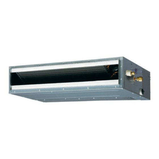
- Page 1 Installatiehandleiding INBOUW UNITS Slim duct / KLL serie Binnenunit ARXG 09 KLLAP ARXG 1 2 KLLAP ARXG 1 4 KLLAP ARXG 1 8 KLLAP Voor gebruik door de professional. Te bewaren door de gebruiker voor toekomstig gebruik.
-
Page 2: Table Of Contents
AIR CONDITIONER INSTALLATION MANUAL Duct type PART No. 9374342532 [Original instructions] For authorized service personnel only. WARNING • The appliance shall be installed, operated and stored in a room with a fl oor area larger than X m². Amount of refrigerant charge Minimum room area M (kg) X (m... -
Page 3: Precautions For Using R32 Refrigerant
1.1. Precautions for using R32 refrigerant CAUTION 2-5 No ignition sources The basic installation work procedures are the same as conventional refrigerant (R410A, • No person carrying out work in relation to a refrigeration system which involves R22) models. exposing any pipe work that contains or has contained fl ammable refrigerant shall However, pay careful attention to the following points: use any sources of ignition in such a manner that it may lead to the risk of fi... - Page 4 CAUTION CAUTION 5-Cabling 10-Decommissioning • Check that cabling will not be subject to wear, corrosion, excessive pressure, vibra- • Before carrying out this procedure, it is essential that the technician is completely tion, sharp edges or any other adverse environmental effects. familiar with the equipment and all its details.
-
Page 5: Product Specification
Coupler heat insulation (large) 2. PRODUCT SPECIFICATION Hose band 2.1. Installation tools Coupler heat insulation(small) Drain hose insulation B Tool name Change from R22 to R32 (R410A) Pressure is high and cannot be measured with a R22 gauge. To prevent erroneous mixing of other refrigerants, the diameter of each port has been changed. -
Page 6: Optional Parts
3.2. Installation dimensions 2.5. Optional parts Refer to each installation manual for the method of installing optional parts. Provide a Service access for inspection purposes. Do not place any wiring or illumination in the service space, as they will impede service. Parts name Model No. - Page 7 Outlet side CAUTION • Check that duct work does not exceed the range of external static pressure of equip- ment. • Make sure to insulate ducts to avoid the dew condensation. • Make sure to insulate between ducts and walls if metal ducts are used. •...
-
Page 8: Drain Installation
3.3.4. Fix the unit 3.4. Drain installation (1) Hang the unit Hanger 3.4.1. Installing drain pipes Hanger bolt WARNING Nut A • Do not insert the drain piping into the sewer where sulfurous gas occurs. (Heat ex- (Locally purchased) change erosion may occur) •... - Page 9 • Provide a downward gradient (1/100 or more). (2) Be sure to connect Drain pipe with adhesive (polyvinyl chloride) so that there is no • Provide supporters when long pipes are installed. leakage. • Use an insulation material as needed, to prevent the pipes from freezing. Applying •...
-
Page 10: Pipe Installation
• When drain pump is used. When using conventional fl are tools to fl are R32 pipes, the dimension A should be approx- imately 0.5 mm more than indicated in the table (for fl aring with R32 fl are tools) to achieve the specifi... -
Page 11: Electrical Wiring
3.6.1. Wiring system diagram 3.6. Electrical wiring ■ Standard pair Connection cable WARNING Indoor unit Outdoor unit Earth (Ground) line • Electrical work must be performed in accordance with this Manual by a person certifi ed Power line under the national or regional regulations. Be sure to use a dedicated circuit for the unit. - Page 12 ■ Simultaneous twin (18 model only) ■ Simultaneous triple (18 model only) Connection cable Connection cable Indoor unit Junction box (Locally purchased) Junction box (Locally purchased) Indoor unit (Primary) Earth (Ground) line Outdoor unit (Primary) Earth (Ground) line Outdoor unit Indoor unit Earth (Ground) line Earth (Ground) line...
- Page 13 3.6.2. Connection cable preparation ■ Connection cable ■ Connection cable Keep the earth (ground) wire longer than the other wires. Connection cable Control line Earth (Ground) wire Power line Connection cable Outdoor • Use a 4-core wire cable. (power supply) unit Earth (ground) ■...
-
Page 14: Remote Controller Setting
(4) Seal the cable outlet or other gaps with putty to prevent dew condensation or insect Terminal from entering the electric control box. (5) Replace the control box cover. TO REMOTE CONTROL UNIT Ex IN CAUTION Do not bundle the remote controller cable, or wire the remote controller cable in par- allel, with the indoor unit connection wire (to the outdoor unit) and the power supply cable. -
Page 15: Remote Sensor (Optional Parts)
■Operation behavior 4.5. Auto louver grille (Optional parts) *If function setting “60” is set to “00” 4.5.1. Connection method • Wiring arrangement Function setting Status Output voltage Controller PCB Stop Operation DC 12 V Normal Error DC 12 V Indoor unit fan stop Indoor unit fan operation DC 12 V External heater OFF... -
Page 16: Optional Parts Cable Binding
(2) Set the R.C. address (DIP switch setting) 4.7. Optional parts cable binding Set the R.C. address of each indoor unit using the DIP switch on the indoor unit circuit board. Bushing** Insulation Air inlet Other optional parts cables Remote controller Cable tie cable (medium,... -
Page 17: Multiple Remote Control
■ Settings when simultaneous Multi is included 5.2. Multiple remote control (3) Set the refrigerant circuit address (Remote controller setting) 1. Turn on all of the indoor units. Up to 2 remote controllers can be used to operate one indoor unit * Turn on the indoor unit with the R.C. -
Page 18: Simultaneous Multi-System Operation
3. After completing the function settings, turn off all of the indoor units, and then turn 5.4. Simultaneous multi-system operation them back on. * If error code 21, 22, 24 or 27 is displayed, there may be an incorrect setting. Perform the remote controller setting again. - Page 19 ■ Room temperature control for indoor unit sensor ■ Remote controller custom code (Only for wireless remote controller) Depending on the installed environment, correction of the room temperature sensor may The indoor unit custom code can be changed. Select the appropriate custom code. be required.
-
Page 20: Test Run
7. TEST RUN 10. ERROR CODES If you use a wireless remote controller, the lamp on the photo detector unit will output error 7.1. Check items codes by way of blinking patterns. If you use a wired remote controller, error codes will ap- pear on the remote control display. - Page 21 Error display Error display OPERATION TIMER ECONOMY OPERATION TIMER ECONOMY Error code Description Error code Description lamp lamp lamp lamp lamp lamp (green) (orange) (green) (green) (orange) (green) Compressor rotor position Filter set error ● ● detection error (permanent stop) Damper error Outdoor unit fan motor 1 error ...