D-Link DES-3018 User Manual
Managed 8/16/24-port 10/100mbps n-way fast ethernet switch
Hide thumbs
Also See for DES-3018:
- Command line interface manual (231 pages) ,
- Manual (225 pages) ,
- User manual (225 pages)

Related Manuals for D-Link DES-3018


Summary of Contents for D-Link DES-3018
- Page 1 DES-3010F/DES-3010FL/DES-3010G/DES-3016/DES-3018/DES-3026 Managed 8/16/24-port 10/100Mbps N-Way Fast Ethernet Switch Release 4.2 Manual...
- Page 2 Microsoft Corporation. Other trademarks and trade names may be used in this document to refer to either the entities claiming the marks and names or their products. D-Link Computer Corporation disclaims any proprietary interest in trademarks and trade names other than its own.
-
Page 3: Table Of Contents
The Optional Modules ...10 Connecting the Switch ...12 Switch to End Node ...12 Switch to Hub or Switch ...13 DES-3010F/FL/G, DES-3016/DES-3018 or DES-3026 as a Network Backbone...14 Introduction to Switch Management ...15 Management Options ... 15 Web-based Management Interface...15 SNMP-Based Management...15 Command Line Console Interface through the Serial Port...15... - Page 4 SNMP Community Table...52 SNMP Host Table ...53 SNMP Engine ID ...54 IP-MAC-Port Binding (IMPB)... 55 IP-MAC-Port Binding (IMPB)...55 IP-MAC Binding Table...56 IP-MAC Binding Blocked...58 D-Link Single IP Management ... 59 Single IP Management (SIM) Overview...59 SIM Using the Web Interface...60 Topology...61...
- Page 5 SMTP Server Settings...76 SMTP Service ...77 DHCP/BOOTP Relay... 78 DHCP/BOOTP Relay Global Settings ...78 The Implementation of DHCP Information Option 82 on the Switch...80 DHCP/BOOTP Relay Interface Settings...80 DHCP Relay Option 60 Default Settings ... 81 DHCP Relay Option 60 Settings... 82 DHCP Relay Option 61 Default Settings ...
- Page 6 IGMP Snooping ... 97 Static Router Ports Settings...99 IGMP Access Control Settings ...100 Spanning Tree ... 101 802.1w Rapid Spanning Tree...101 Port Transition States...101 Edge Port ...102 P2P Port ...102 802.1D and 802.1w Compatibility...102 STP Bridge Global Settings ...102 STP Port Settings ...105 Loopback Detection ...
- Page 7 Received (RX) ...174 Transmitted (TX) ...176 Packet Size ... 178 VLAN Status... 180 MAC Address ... 181 Switch Log ... 182 Log Settings ...183 IGMP Snooping Group ...184 Browse Router Port ... 185 Browse ARP Table... 185 Session Table ... 185 Port Access Control...
- Page 8 Logout ... 199 Appendix A ...200 Appendix B ...203 Cables and Connectors... 203 Appendix C ...204 System Log Entries ... 204 Appendix D ...209 Cable Lengths ... 209 Glossary ...210 Warranties and Registration ... 212 Tech Support ...218...
-
Page 9: Preface
Services, Ping Test, SNMP Manager, IP-MAC Binding, Single IP Setting, Forwarding & Filtering, SMTP Service and DHCP/BOOTP Relay. Section 7, L2 Features - A discussion of the layer 2 features of the Switch, including Static VLAN Entry, VLAN Trunk Settings, Trunking, IGMP Snooping, Spanning Tree and Loopback Detection. -
Page 10: Intended Readers
DES-3010F/DES-3010FL/DES-3010G/DES-3016/DES-3018/DES-3026 Fast Ethernet Switch Manual Intended Readers The DES-3010F/DES-3010FL/DES-3010G/DES-3016/DES-3018/DES-3026 User Manual contains information for setup and management of the Switch. This manual is intended for network managers familiar with network management concepts and terminology. Typographical Conventions Convention Description In a command line, square brackets indicate an optional entry. For example: [copy filename] means that optionally you can type copy followed by the name of the file. -
Page 11: Safety Instructions
• To help avoid damaging your system, be sure the voltage selection switch (if provided) on the power supply is set to match the power available at your location: •... - Page 12 DES-3010F/DES-3010FL/DES-3010G/DES-3016/DES-3018/DES-3026 Fast Ethernet Switch Manual • Observe extension cable and power strip ratings. Make sure that the total ampere rating of all products plugged into the extension cable or power strip does not exceed 80 percent of the ampere ratings limit for the extension cable or power strip.
-
Page 13: Protecting Against Electrostatic Discharge
DES-3010F/DES-3010FL/DES-3010G/DES-3016/DES-3018/DES-3026 Fast Ethernet Switch Manual CAUTION: Never defeat the ground conductor or operate the equipment in the absence of a suitably installed ground conductor. Contact the appropriate electrical inspection authority or an electrician if you are uncertain that suitable grounding is available. -
Page 14: Introduction
200 Mbps of throughput in full-duplex mode. The open slots available on the DES-3018/DES-3026 models, the gigabit port on the DES-3010G and the fiber-optic port on the DES-3010F and DES-3010FL can provide an uplink to a server or network backbone. - Page 15 DES-3010F/DES-3010FL/DES-3010G/DES-3016/DES-3018/DES-3026 Fast Ethernet Switch Manual • Single IP Management support • Simple Network Time Protocol support • System and Port Utilization support • System Log Support • Non-blocking store and forward switching scheme capability to support rate adaptation and protocol conversion •...
-
Page 16: Ethernet Technology
For Fast Ethernet or Gigabit Ethernet networks, a switch is an effective way of eliminating problems of chaining hubs beyond the "two-repeater limit." A switch can be used to split parts of the network into different collision domains, for example, making it possible to expand your Fast Ethernet network beyond the 205-meter network diameter limit for 100BASE-TX networks. - Page 17 Today's switches are an ideal solution to most kinds of local area network congestion problems. NOTE: For customers interested in D-View, D-Link Corporation's proprietary SNMP management software, go to the D-Link Website (www.dlink.com) and download the software and manual.
-
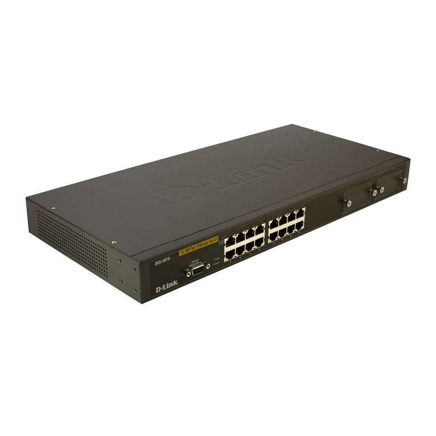
Page 18: Front-Panel Components And Led Indicators
The front panel of the Switch consists of LED indicators for Power, Console, Link/Act and Speed, 8/16/24 Fast-Ethernet ports (DES-3010F, DES-3010FL, DES-3010G, DES-3016, DES-3018, DES-3026), two optional module ports (DES-3018/3026 only), a gigabit 1000BASE-T copper port (DES-3010F/FL/G), a 100BASE-FX Ethernet port (DES-3010F, DES-3010FL only) and a SFP Gigabit Ethernet port (DES- 3010G). - Page 19 1000Mbps and a dark LED indicates no link DES-3018 / DES-3016 / DES-3026 – A solid green LED will indicate a valid link at 100Mbps, and when blinking, indicates the port is currently transferring data. A solid amber LED will indicate a valid link at 10Mbps, and when blinking, indicates the port is currently transferring data.
-
Page 20: Rear Panel Description
Both panels of the Switch contain a heat vent used to dissipate heat. Do not block these openings, and leave at least 6 inches of space at the rear and sides of the Switch for proper ventilation. Be reminded that without proper heat dissipation and air circulation, system components might overheat, which could lead to system failure. -
Page 21: Installation
The site where you install the Switch may greatly affect its performance. Please follow these guidelines for setting up the Switch. • Install the Switch on a sturdy, level surface that can support the weight of the Switch. Do not place heavy objects on the Switch. •... -
Page 22: Installing The Switch Without The Rack
Figure 2- 3. Installing Switch in a rack Power On Plug one end of the AC power cord into the power connector of the Switch and the other end into the local power source outlet. After the Switch is powered on, the LED indicators will momentarily blink. This blinking of the LED indicators represents a reset of the system. -
Page 23: The Optional Modules
The Optional Modules At the front right of the DES-3018 and the DES-3026 resides an optional module slot. These optional modules, specially designed for this Switch series, may be used as an uplink to a server or core switch. This slot may be equipped with a single-port Uplink Module, sold separately. - Page 24 Switch as well. At the front of the Switch to the right is the slot for the optional module, as shown in Figure 2-8 and Figure 2-9. This slot should be covered with a faceplate that can be easily removed by loosening the screws and pulling off the plate.
-
Page 25: Connecting The Switch
End nodes include PCs outfitted with a 10, 100 or 1000 Mbps RJ 45 Ethernet Network Interface Card (NIC) and most routers. An end node can be connected to the Switch via a twisted-pair UTP/STP cable. The end node should be connected to any of the 10/100BASE-T ports of the Switch. -
Page 26: Switch To Hub Or Switch
These connections can be accomplished in a number of ways using a normal cable. • A 10BASE-T hub or switch can be connected to the Switch via a twisted-pair Category 3, 4 or 5 UTP/STP cable. • A 100BASE-TX hub or switch can be connected to the Switch via a twisted-pair Category 5 UTP/STP cable. -
Page 27: Des-3010F/Fl/G, Des-3016/Des-3018 Or Des-3026 As A Network Backbone
PCs, printers, hubs, routers or other switches. The topology configurations are endless but be sure that connections coming from the Switch are at a equal or slower speed than the ISP uplink to avoid bottlenecking. -
Page 28: Introduction To Switch Management
Command Line Console Interface through the Serial Port You can also connect a computer or terminal to the serial console port to access the Switch. The command- line-driven interface provides complete access to all Switch management features. - Page 29 DES-3010F/DES-3010FL/DES-3010G/DES-3016/DES-3018/DES-3026 Fast Ethernet Switch Manual To connect a terminal to the console port: 1. Connect the female connector of the RS-232 cable directly to the console port on the Switch, and tighten the captive retaining screws. 2. Connect the other end of the cable to a terminal or to the serial connector of a computer running terminal emulation software.
-
Page 30: First Time Connecting To The Switch
NOTE: The passwords used to access the Switch are case-sensitive; therefore, "S" is not the same as "s." When you first connect to the Switch, you will be presented with the first login screen (shown below). NOTE: Press Ctrl+R to refresh the screen. This command can be used at any time to force the console program in the Switch to refresh the console screen. -
Page 31: Password Protection
The DES-3010F/DES-3010FL/DES-3010G/DES-3016/DES-3018/DES-3026 switch does not have a default user name and password. One of the first tasks when setting up the Switch is to create user accounts. If you log in using a predefined administrator-level user name, you have privileged access to the Switch's management software. -
Page 32: Traps
The DES-3026 switch supports SNMP versions 1, 2c, and 3. You can specify which version of SNMP you want to use to monitor and control the Switch. The three versions of SNMP vary in the level of security provided between the management station and the network device. -
Page 33: Ip Address Assignment
The Switch's MAC address can also be found from the Web management program on the DES-3028 Web Management Tool. The IP address for the Switch must be set before it can be managed with the Web-based manager. The Switch IP address can be automatically set using BOOTP or DHCP protocols, in which case the actual address assigned to the Switch must be known. -
Page 34: Connecting Devices To The Switch
Figure 4- 6. Assigning the Switch an IP Address In the above example, the Switch was assigned an IP address of 10.7.3.21 with a subnet mask of 255.0.0.0. The system message Success indicates that the command was executed successfully. The Switch can now be configured and managed via Telnet and the CLI or via the Web-based management. -
Page 35: Introduction To Web-Based Switch Configuration
Logging on to the Web Manager To begin managing the Switch, simply run the browser you have installed on your computer and enter the IP address you have defined for the device. The URL in the address bar should read something like: http://123.123.123.123, where the numbers 123 represent the IP address of the Switch. -
Page 36: Web-Based User Interface
The Switch management features available in the web-based manager are explained below. Web-based User Interface The user interface provides access to various Switch configuration and management screens, allows you to view performance statistics, and permits you to graphically monitor the system status. - Page 37 Select the menu or window to be displayed. The folder icons can be opened to display the hyper- Area 1 linked menu buttons and subfolders contained within them. Click the D-Link logo to go to the D-Link website. Area 2 Presents a graphical near real-time image of the front panel of the Switch.
-
Page 38: Web Pages
DES-3010F/DES-3010FL/DES-3010G/DES-3016/DES-3018/DES-3026 Fast Ethernet Switch Manual Web Pages When you connect to the management mode of the Switch with a web browser, a login screen is displayed. Enter a user name and password to access the Switch's management mode. Below is a list and description of the main folders available in the web interface:... -
Page 39: Administration
DES-3010F/DES-3010FL/DES-3010G/DES-3016/DES-3018/DES-3026 Fast Ethernet Switch Manual Section 6 Administration Device Information IP Address Port Configuration User Accounts Password Encryption Cable Diagnostics Port Mirroring System Log Settings SNTP Settings MAC Notification Settings TFTP Services Ping Test SNMP Manager IP-MAC Binding Single IP Setting... -
Page 40: Device Information
DES-3010F/DES-3010FL/DES-3010G/DES-3016/DES-3018/DES-3026 Fast Ethernet Switch Manual Device Information Device Information shows the Switch's MAC Address (assigned factory unchangeable), Boot Firmware Version, and Hardware Version. This information is helpful to keep track of PROM and firmware updates and to obtain the Switch's... -
Page 41: Ip Address
2. Enter the appropriate IP Address and Subnet Mask. 3. If you want to access the Switch from a different subnet from the one it is installed on, enter the IP address of the Default Gateway. If you will manage the Switch from the subnet on which it is installed, you can leave the default address (0.0.0.0) in this field. - Page 42 DES-3010F/DES-3010FL/DES-3010G/DES-3016/DES-3018/DES-3026 Fast Ethernet Switch Manual server. If this option is set, the Switch will first look for a BOOTP server to provide it with this information before using the default or previously entered settings. DHCP The Switch will send out a DHCP broadcast request when it is powered up. The DHCP protocol allows IP addresses, network masks, and default gateways to be assigned by a DHCP server.
-
Page 43: Setting The Switch's Ip Address Using The Console Interface
IP address is 10.90.90.90. You can change the default Switch IP address to meet the specification of your networking address scheme. The IP address for the Switch must be set before it can be managed with the Web-based manager. The Switch IP address can be automatically set using BOOTP or DHCP protocols, in which case the actual address assigned to the Switch must be known. -
Page 44: Port Configuration
DES-3010F/DES-3010FL/DES-3010G/DES-3016/DES-3018/DES-3026 Fast Ethernet Switch Manual Port Configuration This section contains information for configuring various attributes and properties for individual physical ports, including port speed and includes windows for Port Settings, Port Description and Port Error Disabled. Port Settings Click Administration > Port Configuration > Port Settings to display the following window: To configure switch ports: Choose the port or sequential range of ports using the From…To…... - Page 45 Toggle the State <Enabled> field to either enable or disable a given port or group of ports. MDIX Medium dependent interface crossover is a female port connection on the Switch used to connect to end stations, servers and hubs. The drop down menu allows the user to choose between Auto, Normal or Cross.
-
Page 46: Port Description
DES-3010F/DES-3010FL/DES-3010G/DES-3016/DES-3018/DES-3026 Fast Ethernet Switch Manual Port Description The Switch supports a port description feature where the user may name various ports on the Switch. To assign names to various ports, click Administration > Port Configuration > Port Description the following window will be displayed: Use the From and To pull-down menu to choose a port or range of ports to describe, and then enter a description of the port(s). -
Page 47: Port Error Disabled
DES-3010F/DES-3010FL/DES-3010G/DES-3016/DES-3018/DES-3026 Fast Ethernet Switch Manual Port Error Disabled The following window is used to view information about ports that have had their connection status disabled, due to the detection of some storm control anomaly. To view the following window, click Administration >... -
Page 48: User Accounts
DES-3010F/DES-3010FL/DES-3010G/DES-3016/DES-3018/DES-3026 Fast Ethernet Switch Manual User Accounts Use the User Accounts Management window to control user privileges of different accounts on the Switch. To view existing User Accounts, click Administration > User Accounts Figure 6- 6. User Accounts window To add a new user, click on the Add button. To modify or delete an existing user, click on the Modify button for that user. -
Page 49: Admin And User Privileges
DES-3010F/DES-3010FL/DES-3010G/DES-3016/DES-3018/DES-3026 Fast Ethernet Switch Manual Admin and User Privileges There are two levels of user privileges, Admin and User. Some menu selections available to users with Admin privileges may not be available to those with User privileges. The following table summarizes the Admin and User privileges:... -
Page 50: Password Encryption
DES-3010F/DES-3010FL/DES-3010G/DES-3016/DES-3018/DES-3026 Fast Ethernet Switch Manual Password Encryption This window is used to control the password encryption on the Switch. To enable or disable Password Encryption, open Administration > Password Encryption which will display the following window: Figure 6- 10. Password Encryption window... -
Page 51: Port Mirroring
Port Mirroring The Switch allows you to copy frames transmitted and received on a port and redirect the copies to another port. You can attach a monitoring device to the mirrored port, such as a sniffer or an RMON probe, to view details about the packets passing through the first port. -
Page 52: System Log Settings
DES-3010F/DES-3010FL/DES-3010G/DES-3016/DES-3018/DES-3026 Fast Ethernet Switch Manual System Log Settings The Switch can send Syslog messages to up to four designated servers using the Current System Log Host window. Click Administration > System Log Settings, to view the screen shown below. The parameters configured for adding and editing System Log Server settings are the same. To add a new Syslog Server, click the Add button. - Page 53 DES-3010F/DES-3010FL/DES-3010G/DES-3016/DES-3018/DES-3026 Fast Ethernet Switch Manual UDP Port (514 or Enter the UDP port number used for sending Syslog messages. The default is 514. 5000-65535) Status Choose Enabled or Disabled to activate or deactivate. To set the System Log Server configuration, click Apply. To delete an entry from the Current System Log...
-
Page 54: Sntp Settings
DES-3010F/DES-3010FL/DES-3010G/DES-3016/DES-3018/DES-3026 Fast Ethernet Switch Manual SNTP Settings Time Settings This window is used to configure the time settings for the Switch. To view this window click, Administration > SNTP Settings > Time Settings. The following parameters can be set or are displayed:... -
Page 55: Time Zone And Dst
DES-3010F/DES-3010FL/DES-3010G/DES-3016/DES-3018/DES-3026 Fast Ethernet Switch Manual Time in HH MM SS Enter the current time in hours, minutes and seconds, if you would like to update the system clock. Click Apply to implement your changes. Time Zone and DST The following are screens used to configure time zones and Daylight Savings time settings for SNTP. To display this window click Administration >... - Page 56 DES-3010F/DES-3010FL/DES-3010G/DES-3016/DES-3018/DES-3026 Fast Ethernet Switch Manual Using repeating mode will enable DST seasonal time adjustment. Repeating mode requires that the DST beginning and ending date be specified using a formula. For example, specify to begin DST on Saturday during the second week of April and end DST on Sunday during the last week of October.
-
Page 57: Mac Notification Settings
DES-3010F/DES-3010FL/DES-3010G/DES-3016/DES-3018/DES-3026 Fast Ethernet Switch Manual MAC Notification Settings MAC Notification is used to monitor MAC addresses learned and entered into the forwarding database. To globally set MAC notification on the Switch, open the following window Administration > MAC Notification Settings. -
Page 58: Tftp Services
Trivial File Transfer Protocol (TFTP) services allow the Switch’s firmware to be upgraded by transferring a new firmware file from a TFTP server to the Switch or vice versa. Use the pull-down menu to select the service to be completed. Download Firmware is used to transfer a firmware file from an outside source to the Switch using the TFTP Protocol. -
Page 59: Snmp Manager
The DES-3000 Switch Series supports the SNMP versions 1, 2c, and 3. You can specify which version of the SNMP you want to use to monitor and control the Switch. The three versions of SNMP vary in the level of security provided between the management station and the network device. -
Page 60: Snmp Trap Settings
DES-3010F/DES-3010FL/DES-3010G/DES-3016/DES-3018/DES-3026 Fast Ethernet Switch Manual SNMP Trap Settings The following window is used to enable and disable trap settings for the SNMP function on the Switch. To view this window, click Administration > SNMP Manager > SNMP Trap Settings Figure 6- 20. SNMP Trap Settings window To enable or disable the Traps State and/or the Authenticate Traps State, use the corresponding pull-down menu to change and click Apply. - Page 61 DES-3010F/DES-3010FL/DES-3010G/DES-3016/DES-3018/DES-3026 Fast Ethernet Switch Manual Group Name This name is used to specify the SNMP group created can request SNMP messages. V1 - Indicates that SNMP version 1 is in use. SNMP Version V2 - Indicates that SNMP version 2 is in use.
-
Page 62: Snmp View Table
DES-3010F/DES-3010FL/DES-3010G/DES-3016/DES-3018/DES-3026 Fast Ethernet Switch Manual To implement changes made, click Apply. To return to the SNMP User Table, click the User Table Entries link. SNMP View Table The SNMP View Table is used to assign views to community strings that define which MIB objects can be accessed by a remote SNMP manager. -
Page 63: Snmp Group Table
DES-3010F/DES-3010FL/DES-3010G/DES-3016/DES-3018/DES-3026 Fast Ethernet Switch Manual View Type Select Included to include this object in the list of objects that an SNMP manager can access. Select Excluded to exclude this object from the list of objects that an SNMP manager can access. - Page 64 DES-3010F/DES-3010FL/DES-3010G/DES-3016/DES-3018/DES-3026 Fast Ethernet Switch Manual To add a new entry to the Switch's SNMP Group Table, click the Add button in the upper left-hand corner of the SNMP Group Table page. This will open the SNMP Group Table Configuration page, as shown below.
-
Page 65: Snmp Community Table
Use this table to create an SNMP community string to define the relationship between the SNMP manager and an agent. The community string acts like a password to permit access to the agent on the Switch. One or more of the following characteristics can be associated with the community string: •... -
Page 66: Snmp Host Table
To delete an existing SNMP Host Table entry, click the corresponding To add a new entry to the Switch's SNMP Host Table, click the Add button in the upper left-hand corner of the page. This will open the SNMP Host Table Configuration page, as shown below. -
Page 67: Snmp Engine Id
The Engine ID is a unique identifier used for SNMP V3 implementations. This is an alphanumeric string used to identify the SNMP engine on the Switch. To display the Switch's SNMP Engine ID, click Administration > SNMP Manager > SNMP Engine ID Figure 6- 31. SNMP Engine ID Configuration window... -
Page 68: Ip-Mac-Port Binding (Impb)
Binding these two address types together allows the transmission of data between the layers. The primary purpose of IP-MAC binding is to restrict the access to a switch to a number of authorized users. Only the authorized client can access the Switch’s port by checking the pair of IP-MAC addresses with the pre- configured database. -
Page 69: Ip-Mac Binding Table
DES-3010F/DES-3010FL/DES-3010G/DES-3016/DES-3018/DES-3026 Fast Ethernet Switch Manual Figure 6- 32. IP-MAC Binding Ports window When IP-MAC Binding Ports are enabled, use the IP-MAC Binding menu to configure the IP-MAC binding as applied to the enabled ports. IP-MAC Binding Table The IP-MAC Binding Table can be used to create IP-MAC binding entries. Enter the IP and MAC addresses... - Page 70 The Address Binding Trap Log Settings field will enable and disable the sending of trap log messages for IP-MAC binding. When enabled, the Switch will send a trap log message to the SNMP agent and the Switch log when an ARP packet is received that doesn’t match the IP-MAC binding configuration set on the Switch.
-
Page 71: Ip-Mac Binding Blocked
DES-3010F/DES-3010FL/DES-3010G/DES-3016/DES-3018/DES-3026 Fast Ethernet Switch Manual IP-MAC Binding Blocked To view unauthorized devices that have been blocked by IP-MAC binding restrictions open the IP-MAC Binding Blocked window shown below. To view this table click Administration > IP-MAC Binding > IP-MAC Binding Blocked Figure 6- 34. -
Page 72: D-Link Single Ip Management
Member Switch (MS), which is a switch that is recognized by the CS a member of a SIM group, and a Candidate Switch (CaS), which is a Switch that has a physical link to the SIM group but has not been recognized by the CS as a member of the SIM group. -
Page 73: Sim Using The Web Interface
Parameters Description SIM State Use the pull down menu to either enable or disable the SIM state on the Switch. Disabled will render all SIM functions on the Switch inoperable. Role State Use the pull down menu to change the SIM role of the Switch. The two choices are: •... -
Page 74: Topology
DES-3010F/DES-3010FL/DES-3010G/DES-3016/DES-3018/DES-3026 Fast Ethernet Switch Manual Holdtime This parameter may be set for the time, in seconds the Switch will hold information sent to it from other switches, utilizing the Discovery Interval. The user may set the hold time from 100 to 255 seconds. - Page 75 DES-3010F/DES-3010FL/DES-3010G/DES-3016/DES-3018/DES-3026 Fast Ethernet Switch Manual Speed Displays the connection speed between the CS and the MS or CaS. Displays the number of the physical port on the MS or CaS that the CS is connected to. The Remote Port CS will have no entry in this field.
-
Page 76: Tool Tips
DES-3010F/DES-3010FL/DES-3010G/DES-3016/DES-3018/DES-3026 Fast Ethernet Switch Manual Layer 2 member switch. Layer 3 member switch Member switch of other group Layer 2 candidate switch Layer 3 candidate switch Unknown device Non-SIM devices Tool Tips In the Topology view window, the mouse plays an important role in configuration and in viewing device information. - Page 77 DES-3010F/DES-3010FL/DES-3010G/DES-3016/DES-3018/DES-3026 Fast Ethernet Switch Manual Figure 6- 40. Port Speed Utilizing the Tool Tip...
-
Page 78: Right Click
DES-3010F/DES-3010FL/DES-3010G/DES-3016/DES-3018/DES-3026 Fast Ethernet Switch Manual Right Click Right clicking on a device will allow the user to perform various functions, depending on the role of the Switch in the SIM group and the icon associated with it. Group Icon The following options may appear for the user to configure: •... -
Page 79: Member Switch Icon
DES-3010F/DES-3010FL/DES-3010G/DES-3016/DES-3018/DES-3026 Fast Ethernet Switch Manual The following options may appear for the user to configure: • Collapse - to collapse the group that will be represented by a single icon. • Expand - to expand the SIM group, in detail. -
Page 80: Candidate Switch Icon
Add to group - add a candidate to a group. Clicking this option will reveal the following screen for the user to enter a password for authentication from the Candidate Switch before being added to the SIM group. Click OK to enter the password or Cancel to exit the window. -
Page 81: Menu Bar
DES-3010F/DES-3010FL/DES-3010G/DES-3016/DES-3018/DES-3026 Fast Ethernet Switch Manual This window holds the following information: Parameter Description Device Name This field will display the Device Name of the switches in the SIM group configured by the user. If no Device Name is configured by the name, it will be given the name default and tagged with the last six digits of the MAC Address to identify it. -
Page 82: Group
Add to group - add a candidate to a group. Clicking this option will reveal the following screen for the user to enter a password for authentication from the Candidate Switch before being added to the SIM group. Click OK to enter the password or Cancel to exit the window. -
Page 83: Firmware Upgrade
The following window is used to upload log files from SIM member switches to a specified PC. To upload a log file, enter the IP address of the SIM member switch and then enter a path on your PC where you wish to save this file. - Page 84 DES-3010F/DES-3010FL/DES-3010G/DES-3016/DES-3018/DES-3026 Fast Ethernet Switch Manual Figure 6- 55. Upload Log File window...
-
Page 85: Forwarding & Filtering
DES-3010F/DES-3010FL/DES-3010G/DES-3016/DES-3018/DES-3026 Fast Ethernet Switch Manual Forwarding & Filtering Unicast Forwarding To view or configure the Unicast Forwarding window click, Administration > Forwarding & Filtering > Unicast Forwarding Figure 6- 56. Setup Static Unicast Forwarding Table and Static Unicast Forwarding Table window... -
Page 86: Multicast Forwarding
DES-3010F/DES-3010FL/DES-3010G/DES-3016/DES-3018/DES-3026 Fast Ethernet Switch Manual Multicast Forwarding The following figure and table describes how to set up Multicast Forwarding on the Switch. To view this window click Administration > Forwarding & Filtering > Multicast Forwarding Figure 6- 57. Static Multicast Forwarding Settings and Current Multicast Forwarding Entries window The Static Multicast Forwarding Settings page displays all of the entries made into the Switch's static multicast forwarding table. -
Page 87: Multicast Filtering Mode
DES-3010F/DES-3010FL/DES-3010G/DES-3016/DES-3018/DES-3026 Fast Ethernet Switch Manual Multicast Filtering Mode Use the Multicast Filtering Mode Setting menu to select one of two filtering options for multicast packets: • Forward unregistered groups – This default setting will forward all multicast streams. • Filter unregistered groups – This setting will only forward multicasts to registered multicast groups. -
Page 88: Smtp Service
Self Mail Address field. • The Switch can be configured to send out test mail to first ensure that the recipient will receive e- mails from the SMTP server regarding the Switch. To configure this test mail, the SMTP function must first be enabled by configuring the SMTP State in the SMTP Service Settings window and then by sending an email using the SMTP Service window. -
Page 89: Smtp Server Settings
SMTP Server Settings The following window is used to configure the fields to set up the SMTP server for the switch, along with setting e-mail addresses to which switch log files can be sent when a problem arises on the Switch. To open the following window, click Administration >... -
Page 90: Smtp Service
Enter the subject of the test e-mail. Content Enter the content of the test e-mail. Once your message is ready, click Send to send this mail to all recipients configured on the Switch for SMTP. Figure 6- 61. SMTP Mail Service... -
Page 91: Dhcp/Bootp Relay
Switch will use that value, along with the hop count to determine whether to forward a given BOOTP or DHCP packet. DHCP Vendor class Allows the user to Enable or Disable the DHCP relay option 60 on the Switch. The default is Identifier option 60 Disabled. - Page 92 Click Apply to implement any changes that have been made. NOTE: If the Switch receives a packet that contains the option-82 field from a DHCP client and the information-checking feature is enabled, the switch drops the packet because it is invalid. However, in some instances, you might configure a client with the option-82 field.
-
Page 93: The Implementation Of Dhcp Information Option 82 On The Switch
The config dhcp_relay option_82 command configures the DHCP relay agent information option 82 setting of the switch. The formats for the circuit ID sub-option and the remote ID sub-option are as follows: NOTE: For the circuit ID sub-option of a standalone switch, the module field is always zero. -
Page 94: Dhcp Relay Option 60 Default Settings
The following parameters may be configured or viewed. Parameter Description Interface The IP interface on the Switch that will be connected directly to the Server. Server IP Enter the IP address of the DHCP/BOOTP server. Up to four server IPs can be configured per IP Interface DHCP Relay Option 60 Default Settings This function allows the user to set up the DHCP Relay Option 60 Default Settings. -
Page 95: Dhcp Relay Option 60 Settings
DES-3010F/DES-3010FL/DES-3010G/DES-3016/DES-3018/DES-3026 Fast Ethernet Switch Manual DHCP Relay Option 60 Settings This window allows the user to choose whether DHCP relay will process the DHCP option or not. When Option 60 is enabled, if the packet doesn’t already have option 60 then the relay servers cannot be determined based on option 60. -
Page 96: Dhcp Relay Option 61 Default Settings
DES-3010F/DES-3010FL/DES-3010G/DES-3016/DES-3018/DES-3026 Fast Ethernet Switch Manual DHCP Relay Option 61 Default Settings This window allows the user to set the default Server IP address. This setting can be used to determine the rule to process the packets that have no option 61 matching rules. The default is Drop. - Page 97 DES-3010F/DES-3010FL/DES-3010G/DES-3016/DES-3018/DES-3026 Fast Ethernet Switch Manual The relay rule is specified to determine that the relay server is based on option 61. When Relay Rule option_61 is enabled, if the packet does not have option 61, then the relay servers cannot be determined based on option 61.
-
Page 98: L2 Features
Ingress port - A port on a switch where packets are flowing into the Switch and VLAN decisions must be made. Egress port - A port on a switch where packets are flowing out of the Switch, either to another switch or to an end station, and tagging decisions must be made. -
Page 99: 802.1Q Vlan Tags
DES-3010F/DES-3010FL/DES-3010G/DES-3016/DES-3018/DES-3026 Fast Ethernet Switch Manual VLANs can also provide a level of security to your network. IEEE 802.1Q VLANs will only deliver packets between stations that are members of the VLAN. Any port can be configured as either tagging or untagging. The untagging feature of IEEE 802.1Q VLANs allows VLANs to work with legacy switches that don't recognize VLAN tags in packet headers. -
Page 100: Tagging And Untagging
Ingress Filtering A port on a switch where packets are flowing into the Switch and VLAN decisions must be made is referred to as an ingress port. If ingress filtering is enabled for a port, the Switch will examine the VLAN information in the packet header (if present) and decide whether or not to forward the packet. -
Page 101: Default Vlans
If the packet is not tagged with VLAN information, the ingress port will tag the packet with its own PVID as a VID (if the port is a tagging port). The switch then determines if the destination port is a member of the same VLAN (has the same VID) as the ingress port. -
Page 102: Static Vlan Entry
DES-3010F/DES-3010FL/DES-3010G/DES-3016/DES-3018/DES-3026 Fast Ethernet Switch Manual Static VLAN Entry The Static VLAN Entry table allows the user to configure the Static VLAN entries for the switch. To view this window click L2 Features > VLAN > Static VLAN Entry Figure 7- 4. 802.1Q Static VLANs window The 802.1Q Static VLANs menu lists all previously configured VLANs by VLAN ID and VLAN Name. - Page 103 DES-3010F/DES-3010FL/DES-3010G/DES-3016/DES-3018/DES-3026 Fast Ethernet Switch Manual The following fields can then be set in either the Add or Modify 802.1Q Static VLANs menus: Parameter Description Allows the entry of a VLAN ID in the Add dialog box, or displays the VLAN ID of an existing VLAN in the Modify dialog box.
-
Page 104: Link Aggregation
Port trunk groups are used to combine a number of ports together to make a single high-bandwidth data pipeline. The Switch supports up to three port trunk groups with 2 to 8 ports in each group. A potential bit rate of 8000 Mbps can be achieved. - Page 105 If two redundant link aggregation groups are configured on the Switch, STP will block one entire group, in the same way STP will block a single port that has a redundant link.
-
Page 106: Vlan Trunk Settings
The VLAN Trunk Settings table allows the user to configure a port or range of ports as VLAN trunk ports, by default none of the ports on the Switch are VLAN trunk ports unless configured. To view this window click L2 Features > VLAN Trunk Settings... -
Page 107: Link Aggregation
DES-3010F/DES-3010FL/DES-3010G/DES-3016/DES-3018/DES-3026 Fast Ethernet Switch Manual Link Aggregation To configure a port trunking group or view the current trunking group entries, click L2 Features > Trunking > Link Aggregation Figure 7- 9. Port Trunking Group window To configure port trunk groups, click the Add button to add a new trunk group and use the Port Trunking Configuration menu (see example below) to set up trunk groups. -
Page 108: Lacp Port Settings
DES-3010F/DES-3010FL/DES-3010G/DES-3016/DES-3018/DES-3026 Fast Ethernet Switch Manual LACP Port Settings This window allows the user to create port trunking groups on the Switch. Using the following window the user may set which ports will be active and passive in processing and sending LACP (Link Aggregation Control Protocol) control frames. - Page 109 DES-3010F/DES-3010FL/DES-3010G/DES-3016/DES-3018/DES-3026 Fast Ethernet Switch Manual allows LACP compliant devices to negotiate the aggregated link so the group may be changed dynamically as needs require. In order to utilize the ability to change an aggregated port group, that is, to add or subtract ports from the group, at least one of the participating devices must designate LACP ports as active.
-
Page 110: Igmp Snooping
Internet Group Management Protocol (IGMP) snooping allows the Switch to recognize IGMP queries and reports sent between network stations or devices and an IGMP host. When IGMP snooping is enabled, the Switch can open or close a port to a specific device based on IGMP messages passing through the Switch. - Page 111 Default = 1. Host Timeout This is the maximum amount of time in seconds allowed for a host to continue membership in a multicast group without the Switch receiving a host membership report. Default = 260. (1-16711450) Router Timeout This is the maximum amount of time in seconds a route is kept in the forwarding table without receiving a membership report.
-
Page 112: Static Router Ports Settings
All UDP multicast packets will be forwarded to the router port. Because routers do not send IGMP reports or implement IGMP snooping, a multicast router connected to the router port of a Layer 3 switch would not be able to receive UDP data streams unless the UDP multicast packets were all forwarded to the router port. -
Page 113: Igmp Access Control Settings
IGMP Access Control Settings This window is used to enable the IGMP access control settings on the switch. When the access control settings are enabled the switch will receive an IGMP join message, the switch will then send the access request to the radius server to complete the authentication process. -
Page 114: Spanning Tree
802.1D STP will be familiar to most networking professionals. However, since 802.1w RSTP has been recently introduced to D-Link managed Ethernet switches, a brief introduction to the technology is provided below followed by a description of how to set up 802.1D STP and 802.1w RSTP. -
Page 115: Edge Port
DES-3010F/DES-3010FL/DES-3010G/DES-3016/DES-3018/DES-3026 Fast Ethernet Switch Manual Edge Port The edge port is a configurable designation used for a port that is directly connected to a segment where a loop cannot be created. An example would be a port connected directly to a single workstation. Ports that are designated as edge ports transition to a forwarding state immediately without going through the listening and learning states. - Page 116 Max. Age ≥ 2 x (Hello Time + 1 second) The following parameters can be set: Parameter Description Spanning Tree Protocol Use the pull-down menu to enable or disable STP globally on the Switch. The default is Disabled. Figure 7- 17. STP Bridge Global Settings...
- Page 117 (4-30 Sec) Bridge Priority (0-61440) A Priority for the Switch can be set from 0 to 61440. This number is used in the voting process between Switches on the network to determine which Switch will be the root Switch. A low number indicates a high priority, and a high probability that this Switch will be elected as the root Switch.
-
Page 118: Stp Port Settings
Port Priority and Port Cost. An STP Group spanning tree works in the same way as the switch-level spanning tree, but the root bridge concept is replaced with a root port concept. A root port is a port of the group that is elected based on port priority and port cost, to be the connection to the network for the group. - Page 119 Setting this parameter as "yes" will set the ports to send out BPDU packets to other bridges, requesting information on their STP setting If the Switch is configured for RSTP, the port will be capable to migrate from 802.1D STP to 802.1w RSTP. Migration should be set as yes on ports connected to network stations or segments that are capable of being upgraded to 802.1w RSTP on all or some portion of the segment.
-
Page 120: Loopback Detection
DES-3010F/DES-3010FL/DES-3010G/DES-3016/DES-3018/DES-3026 Fast Ethernet Switch Manual Loopback Detection The Loopback Detection function is used to identify loops occurring between the Switch and a device that is directly connected This accomplished by the use of a Configuration Testing Protocol (CTP) packet that is generated by the switch. - Page 121 DES-3010F/DES-3010FL/DES-3010G/DES-3016/DES-3018/DES-3026 Fast Ethernet Switch Manual Recover Time Enter a time, in seconds that a port will have to wait before being recovered from a Loopback Detection shutdown. The user may set a time between 60 and 1000000 seconds with a default setting of 60 seconds.
-
Page 122: Cos
Queue 0 and thus given the lowest priority for delivery. A weighted round robin system is employed on the Switch to determine the rate at which the queues are emptied of packets. The ratio used for clearing the queues is 4:1. This means that the highest priority queue, Queue 3, will clear 4 packets for every 1 packet cleared from Queue 0. -
Page 123: The Advantages Of Cos
Switch. In order to implement CoS, the user is required to instruct the Switch to examine the header of a packet to see if it has the proper identifying tag. Then the user may forward these tagged packets to designated classes of service on the Switch where they will be emptied, based on priority. -
Page 124: Understanding Cos
Higher priority packets always receive preference regardless of the amount of lower priority packets in the buffer and regardless of the time elapsed since any lower priority packets have been transmitted. By default, the Switch is configured to empty the buffer using strict priority. -
Page 125: Port Bandwidth
DES-3010F/DES-3010FL/DES-3010G/DES-3016/DES-3018/DES-3026 Fast Ethernet Switch Manual Port Bandwidth The bandwidth control settings are used to place a ceiling on the transmitting and receiving data rates for any selected port. To view this table, click CoS > Port Bandwidth Figure 8- 2. Bandwidth Settings and Port Bandwidth Table window... - Page 126 DES-3010F/DES-3010FL/DES-3010G/DES-3016/DES-3018/DES-3026 Fast Ethernet Switch Manual The following parameters can be set or are displayed: Parameter Description From/To A consecutive group of ports may be configured starting with the selected port. Type This drop-down menu allows you to select between RX (receive,) TX (transmit,) and Both.
-
Page 127: 802.1P Default Priority
Figure 8- 3. 802.1p Default Priority and the 802.1p Default Priority window This page allows you to assign a default 802.1p priority to any given port on the Switch. The priority tags are numbered from 0, the lowest priority, to 7, the highest priority. To implement a new default priority choose a port range by using the From and To pull-down menus and then insert a priority value, from 0-7 in the Priority field. -
Page 128: 802.1P User Priority
CoS > 802.1p User Priority Once you have assigned a priority to the port groups on the Switch, you can then assign this Class to each of the four levels of 802.1p priorities. Click Apply to set your changes. -
Page 129: Cos Output Scheduling
CoS can be customized by changing the output scheduling used for the hardware classes of service in the Switch. As with any changes to CoS implementation, careful consideration should be given to how network traffic in lower priority classes of service is affected. Changes in scheduling may result in unacceptable levels of packet loss or significant transmission delay. -
Page 130: Priority Settings
The Priority Setting window will allow users to configure the CoS priority settings on a port per port basis. When CoS tagged packets arrive on the switch, they are mapped to the settings configured here. For example, if a port has been assigned a MAC priority, the packet that has the CoS priority assigned to a MAC address will be sent to the CoS queue configured for that MAC address. -
Page 131: Tos Priority Settings
TOS Priority Settings Use the TOS Priority Settings menu to configure ToS priority mapping for Class of Service on the Switch. When a packet is received containing this ToS tag, it will be mapped to the CoS queue configured here. -
Page 132: Dscp Priority Settings
DES-3010F/DES-3010FL/DES-3010G/DES-3016/DES-3018/DES-3026 Fast Ethernet Switch Manual DSCP Priority Settings Use the DSCP Priority Settings menu to configure DSCP priority mapping for Class of Service on the Switch. When a packet is received containing this DSCP tag, it will be mapped to the CoS queue configured here. -
Page 133: Port Mapping Priority Settings
Use the Port Mapping Priority Settings menu to configure priority mapping for Class of Service on the Switch. Port Mapping Priority CoS can only be used if it has been previously configured for the selected ports in the Priority Setting menu. There are two Class of Service levels available. To view this table click, CoS >... -
Page 134: Mac Priority Settings
3. Once the previous parameters are set, users should go to the Priority Settings window located in this folder and set the egress ports on the switch to MAC Priority. These ports must only be set for MAC Priority and not for any other priority choice. Please be advised that the default priority setting is for 802.1p and users must change the priority to MAC Priority for this function to work properly. -
Page 135: Cpu Interface Filtering
Due to needed extra switch security, the DES-3000 switch series incorporates CPU Interface filtering. This added feature increases the running security of the Switch by enabling the user to create a list of access rules for packets destined for the Switch’s CPU interface. CPU interface filtering examines Ethernet, IP and Packet Content Mask packet headers destined for the CPU and will either forward them or filter them, based on the user’s implementation. - Page 136 Ethernet (or MAC address-based) profile configuration, one for IP address-based profile configuration and one for the Packet Content Mask. You can switch between the three Access Profile Configuration pages by using the Type drop-down menu. The page shown below is the Ethernet CPU Interface Filtering Configuration page.
- Page 137 DES-3010F/DES-3010FL/DES-3010G/DES-3016/DES-3018/DES-3026 Fast Ethernet Switch Manual header. Ethernet type Selecting this option instructs the Switch to examine the Ethernet type value in each frame's header. Click Apply to set this entry in the Switch’s memory. The page shown below is the CPU IP Access Profile Configuration page.
- Page 138 DES-3010F/DES-3010FL/DES-3010G/DES-3016/DES-3018/DES-3026 Fast Ethernet Switch Manual DSCP Selecting this option instructs the Switch to examine the DiffServ Code part of each packet header and use this as the, or part of the criterion for forwarding. Protocol Selecting this option instructs the Switch to examine the protocol type value in each frame's header.
- Page 139 Figure 9- 5. CPU Interface Filtering Configuration window- Packet Content This screen will aid the user in configuring the Switch to mask packet headers beginning with the offset value specified. The following fields are used to configure the Packet Content Mask:...
- Page 140 DES-3010F/DES-3010FL/DES-3010G/DES-3016/DES-3018/DES-3026 Fast Ethernet Switch Manual To establish the rule for a previously created CPU Access Profile: In the CPU interface folder, click the CPU Interface Filtering State link to open the CPU Interface Filtering Table. Figure 9- 6. CPU Interface Filtering Table In this window, the user may add a rule to a previously created CPU access profile by clicking the corresponding Modify button of the entry to configure, Ethernet, IP and Packet Content.
- Page 141 This is the identifier number for this profile set. Mode Select Permit to specify that packets that match the access profile are forwarded by the Switch, according to any additional rule added (see below). Select Deny to specify that packets that match the access profile are not forwarded by the Switch and will be filtered.
- Page 142 Selected profile based on Ethernet (MAC Address), IP address or Packet Content. • • button. The following window is used for the IP Rule Ethernet instructs the Switch to examine the layer 2 part of each packet header. IP instructs the Switch to examine the IP address in each frame's header.
- Page 143 The Access Rule may be configured on a per-port basis by entering the port number of the Switch into this field. Entering all will denote all ports on the Switch. To view the settings of a previously correctly configured rule, click following screen: Figure 9- 12.
- Page 144 Selected profile based on Ethernet (MAC Address), IP address or Packet Content. • • • Offset This field will instruct the Switch to mask the packet header beginning with the offset value specified: • • Ethernet instructs the Switch to examine the layer 2 part of each packet header.
- Page 145 The Access Rule may be configured on a per-port basis by entering the port number of the Switch into this field. Entering all will denote all ports on the Switch. To view the settings of a previously correctly configured rule, click following screen: Figure 9- 15.
-
Page 146: Security
The packet storm is monitored to determine if too many packets are flooding the network, based on the threshold level provided by the user. Once a packet storm has been detected, the Switch will drop packets coming into the Switch until the storm has subsided. This method can be utilized by selecting the Drop option of the Action field in the window below. - Page 147 Once a storm has been detected (that is, once the packet threshold set below has been exceeded), the Switch will shutdown the port to all incoming traffic with the exception of STP BPDU packets, for a time period specified using the Count Down field. Although the Count Down field can be specified, users are advised to disable this feature and assess the situation before recovering the port.
- Page 148 Switch’s chip to determine if a Packet Storm is occurring. The Count Down timer is set to determine the amount of time, in minutes, that the Switch will wait Count Down before shutting down the port that is experiencing a traffic storm.
- Page 149 DES-3010F/DES-3010FL/DES-3010G/DES-3016/DES-3018/DES-3026 Fast Ethernet Switch Manual NOTE: Traffic Control cannot be implemented on ports that are set for Link Aggregation (Port Trunking). NOTE: Ports that are in the Shutdown (Forever) mode will be seen as Discarding in Spanning Tree windows and implementations though these ports will still be forwarding BPDUs to the Switch’s CPU.
-
Page 150: Port Security
Port Security is a security feature that prevents unauthorized computers (with source MAC addresses) unknown to the Switch prior to locking the port (or ports) from connecting to the Switch's locked ports and gaining access to the network. To view the following window, click Security > Port Security Figure 10- 2. - Page 151 • Click Apply to implement changes made. NOTE: The uplink module ports (DES-3010F/FL/G ports 9-10, DES-3018 ports 17-18, DES-3026 ports 25-26) do not support the port security function. Permanent – The locked addresses will not age out after the aging timer expires.
-
Page 152: Port Lock Entries
Port Lock Entries The Port Lock Entry Delete window is used to remove an entry from the port security entries learned by the Switch and entered into the forwarding database. To view the following window, click Security > Port Lock Entries... -
Page 153: 140
DES-3010F/DES-3010FL/DES-3010G/DES-3016/DES-3018/DES-3026 Fast Ethernet Switch Manual 802.1X 802.1X Port-Based and MAC-Based Access Control The IEEE 802.1X standard is a security measure for authorizing and authenticating users to gain access to various wired or wireless devices on a specified Local Area Network by using a Client and Server based access control model. -
Page 154: Authentication Server
Authentication Server is to certify the identity of the Client attempting to access the network by exchanging secure information between the RADIUS server and the Client through EAPOL packets and, in turn, informs the Switch whether or not the Client is granted access to the LAN and/or switches services. Authenticator The Authenticator (the Switch) is an intermediary between the Authentication Server and the Client. -
Page 155: Client
DES-3010F/DES-3010FL/DES-3010G/DES-3016/DES-3018/DES-3026 Fast Ethernet Switch Manual Client The Client is simply the end station that wishes to gain access to the LAN or switch services. All end stations must be running software that is compliant with the 802.1X protocol. For users running Windows XP, that software is included within the operating system. -
Page 156: Authentication Process
The following figure displays a more detailed explanation of how the authentication process is completed between the three roles stated above. The D-Link implementation of 802.1X allows network administrators to choose between two types of Access Control used on the Switch, which are: Port-Based Access Control –... -
Page 157: Understanding 802.1X Port-Based And Mac-Based Network Access Control
DES-3010F/DES-3010FL/DES-3010G/DES-3016/DES-3018/DES-3026 Fast Ethernet Switch Manual Understanding 802.1X Port-based and MAC-based Network Access Control The original intent behind the development of 802.1X was to leverage the characteristics of point-to-point in LANs. As any single LAN segment in such infrastructures has no more than two devices attached to it, one of which is a Bridge Port. -
Page 158: Mac-Based Network Access Control
In order to successfully make use of 802.1X in a shared media LAN segment, it would be necessary to create “logical” Ports, one for each attached device that required access to the LAN. The Switch would regard the single physical Port connecting it to the shared media segment as consisting of a number of distinct logical Ports, each logical Port being independently controlled from the point of view of EAPOL exchanges and authorization state. -
Page 159: 802.1X Authenticator Settings
DES-3010F/DES-3010FL/DES-3010G/DES-3016/DES-3018/DES-3026 Fast Ethernet Switch Manual 802.1X Authenticator Settings To configure the 802.1X authenticator settings, click Security > 802.1X > 802.1X Authenticator Settings Figure 10- 12. 802.1X Authenticator Settings window To configure the settings by port, click on the hyperlinked port number under the Port heading, which will... - Page 160 This sets the TxPeriod of time for the authenticator PAE state machine. This value determines the period of an EAP Request/Identity packet transmitted to the client. The default setting is 30 seconds. QuietPeriod This allows you to set the number of seconds that the Switch remains in the quiet...
- Page 161 The default setting is 30 seconds. MaxReq The maximum number of times that the Switch will retransmit an EAP Request to the client before it times out of the authentication sessions. The default setting is 2.
-
Page 162: Local Users
DES-3010F/DES-3010FL/DES-3010G/DES-3016/DES-3018/DES-3026 Fast Ethernet Switch Manual Local Users To configure Local Users for 802.1X, click Security > 802.1X > Local Users. This window will allow the user to set different 802.1X local users on the Switch. Figure 10- 14. 802.1X Local User Table Configuration and 802.1X Local User Table window Enter a User Name, Password and confirmation of that password. -
Page 163: 802.1X Capability Settings
Click Security > 802.1X > 802.1X Capability Settings to view the following window: To set up the Switch's 802.1X port-based authentication, select which ports are to be configured in the From and To fields. Next, enable the ports by selecting Authenticator from the drop-down menu under Capability. -
Page 164: Guest Vlans
DES-3010F/DES-3010FL/DES-3010G/DES-3016/DES-3018/DES-3026 Fast Ethernet Switch Manual Guest VLANs On 802.1X security enabled networks, there is a need for non 802.1X supported devices to gain limited access to the network, due to lack of the proper 802.1X software or incompatible devices, such as... -
Page 165: Configure 802.1X Guest Vlan
Delete – Selecting this option will delete the VLAN entered in the VLAN Name window above. Port List Set the port list of ports of switches in the switch stack to be enabled for the Guest 802.1X VLAN using the pull down menus. -
Page 166: Initializing Ports For Port Based 802.1X
A read only field indicating a port on the Switch. MAC Address The MAC address of the Switch connected to the corresponding port, if any. Auth PAE State The Authenticator PAE State will display one of the following: Initialize, Disconnected, Connecting, Authenticating, Authenticated, Aborting, Held, ForceAuth or ForceUnauth. -
Page 167: Initializing Ports For Mac Based 802.1X
Management Tool window before reauthenticating ports. Information in the Initialize Ports Table cannot be viewed before enabling 802.1X. NOTE: The uplink module ports (DES-3010F/FL/G ports 9-10, DES-3018 ports 17-18, DES-3026 ports 25-26) do not support the 802.1X function. Reauthenticate Port(s) for Port Based 802.1X This window allows you to reauthenticate a port or group of ports by choosing a port or group of ports by using the pull down menus From and To and clicking Apply. -
Page 168: Reauthenticate Port(S) For Mac-Based 802.1X
Information in the Reauthenticate Ports Table cannot be viewed before enabling 802.1X. NOTE: The uplink module ports (DES-3010F/G ports 9-10, DES-3018 ports 17-18, DES-3026 ports 25-26) do not support the 802.1X function. Reauthenticate Port(s) for MAC-based 802.1X To reauthenticate ports for the MAC side of 802.1X, the user must first enable 802.1X by MAC address in... -
Page 169: Radius Server
DES-3010F/DES-3010FL/DES-3010G/DES-3016/DES-3018/DES-3026 Fast Ethernet Switch Manual RADIUS Server The RADIUS feature of the Switch allows you to facilitate centralized user administration as well as providing protection against a sniffing, active hacker. The Web Manager offers three windows. To view the following window, click Security > 802.1X > RADIUS Server Figure 10- 22. -
Page 170: Trusted Host
Figure 10- 23. Security IP Management menu Use the Security IP Management to permit remote stations to manage the Switch. If you choose to define one or more designated management stations, only the chosen stations, as defined by IP address and Subnet Mask, will be allowed management privilege through the web manager or Telnet session. -
Page 171: Traffic Segmentation
Traffic segmentation is used to limit traffic flow from a single port to a group of ports on either a single Switch (in standalone mode) or a group of ports on another switch in a switch stack. This method of segmenting the flow of traffic is similar to using VLANs to limit traffic, but is more restrictive. -
Page 172: Secure Shell (Ssh)
Click on the Setup button to open the Setup Forwarding ports page, as shown below. This page allows you to determine which port on a given switch in a switch stack will be allowed to forward packets to other ports on that switch. Configuring traffic segmentation on the Switch is accomplished in two parts. -
Page 173: Ssh Server Configuration
2 and 20. The default setting is 2. Session Rekeying This field is used to set the time period that the Switch will change the security shell encryptions by using the pull-down menu. The available options are Never, 10 min, 30 min, and 60 min. -
Page 174: Ssh Authentication Mode And Algorithm Settings
Description Password This field may be enabled or disabled to choose if the administrator wishes to use a locally configured password for authentication on the Switch. This field is Enabled by default. Public Key This field may be enabled or disabled to choose if the administrator wishes to use a publickey configuration set on a SSH server, for authentication. - Page 175 DES-3010F/DES-3010FL/DES-3010G/DES-3016/DES-3018/DES-3026 Fast Ethernet Switch Manual authentication techniques and the host computer is running the Linux operating system with a SSH program previously installed. This field is Enabled by default. 3DES-CBC Use the pull-down to enable or disable the Triple Data Encryption Standard encryption algorithm with Cipher Block Chaining.
-
Page 176: Ssh User Authentication Mode
DES-3010F/DES-3010FL/DES-3010G/DES-3016/DES-3018/DES-3026 Fast Ethernet Switch Manual SSH User Authentication Mode The following windows are used to configure parameters for users attempting to access the Switch through SSH. To access the following window, click Security > SSH > SSH User Authentication Figure 10- 28. SSH User Authentication Mode window In the example screen above, the User Account “RG”... - Page 177 Password – This parameter should be chosen if the administrator wishes to use an administrator-defined password for authentication. Upon entry of this parameter, the Switch will prompt the administrator for a password, and then to re-type the password for confirmation.
-
Page 178: Monitoring
DES-3010F/DES-3010FL/DES-3010G/DES-3016/DES-3018/DES-3026 Fast Ethernet Switch Manual Monitoring CPU Utilization Port Utilization Packets Packet Errors Packet Size VLAN Status MAC Address Switch Log Log Settings IGMP Snooping Group Browse Router Port Browse ARP Table Session Table Port Access Control CPU Utilization The CPU Utilization displays the percentage of the CPU being used, expressed as an integer percentage and calculated as a simple average by time interval. -
Page 179: Port Utilization
DES-3010F/DES-3010FL/DES-3010G/DES-3016/DES-3018/DES-3026 Fast Ethernet Switch Manual To view the CPU utilization by port, use the real-time graphic of the Switch at the top of the web page by simply clicking on a port. Click Apply to implement the configured settings. Click Clear to automatically refresh with new updated statistics. - Page 180 Select the desired setting between 1s and 60s, where "s" stands for seconds. The default value is one second. Record Number Select number of times the Switch will be polled between 20 and 200. The default value is 200. Click Clear to refresh the graph. Click Apply to implement changes made.
-
Page 181: Packets
Received (RX) This table is used to view the graph of packets received on the Switch. To select a port to view these statistics for, use the Port pull down menu. The user may also use the real-time graphic of the Switch at the top of the web page by simply clicking on a port. - Page 182 Select the desired setting between 1s and 60s, where "s" stands for seconds. The default value is one second. Record Number [200] Select number of times the Switch will be polled between 20 and 200. The default value is 200. Bytes Counts the number of bytes received on the port.
-
Page 183: Umb Cast (Rx)
Port pull down menu. The user may also use the real-time graphic of the Switch at the top of the web page by simply clicking on a port. To view this graph, click Monitoring >... - Page 184 Select the desired setting between 1s and 60s, where "s" stands for seconds. The default value is one second. Record Number [200] Select number of times the Switch will be polled between 20 and 200. The default value is 200. Unicast Counts the total number of good packets that were received by a unicast address.
-
Page 185: Transmitted (Tx)
Transmitted (TX) Transmitted (TX) table allows the user to view the packets transmitted from the Switch. To view statistics for a specific port, use the Port pull down menu. The user may also use the real-time graphic, at the top of the web page by simply clicking on a port. - Page 186 Select the desired setting between 1s and 60s, where "s" stands for seconds. The default Time Interval [1s] value is one second. Record Number [200] Select number of times the Switch will be polled between 20 and 200. The default value is 200. Bytes Counts the number of bytes successfully sent from the port.
-
Page 187: Packet Errors
The table displays the error packets received on the Switch. To view statistics for a specific port, select the port by using the Port pull down menu. The user may also use the real-time graphic of the Switch at the top of the web page by simply clicking on a port. - Page 188 Select the desired setting between 1s and 60s, where "s" stands for seconds. The default value is one second. Record Number [200] Select number of times the Switch will be polled between 20 and 200. The default value is 200. Crc Error Counts otherwise valid packets that did not end on a byte (octet) boundary.
-
Page 189: Transmitted (Tx)
The following graph displays the error packets received on the Switch. To view statistics for a specific port, select the port by using the Port pull down menu. The user may also use the real-time graphic of the Switch at the top of the web page by simply clicking on a port. To view this window, click Monitoring > Packet Errors >... - Page 190 Select the desired setting between 1s and 60s, where "s" stands for seconds. The default value is one second. Record Number [200] Select number of times the Switch will be polled between 20 and 200. The default value is 200. ExDefer Counts the number of packets for which the first transmission attempt on a particular interface was delayed because the medium was busy.
-
Page 191: Packet Size
Port pull down menu. The user may also use the real-time graphic of the Switch at the top of the web page by simply clicking on a port. To view this window, click Monitoring >... - Page 192 Record Number Select number of times the Switch will be polled between 20 and 200. The default value is 200. The total number of packets (including bad packets) received that were 64 octets in length (excluding framing bits but including FCS octets).
-
Page 193: Vlan Status
This allows the VLAN status for each of the Switch's ports to be viewed by VLAN. This window displays the ports on the Switch that are currently Egress (E) or Tag (T) ports. To view the following table, click Monitoring > VLAN Status Figure 11- 15. -
Page 194: Mac Address
The port to which the MAC address above corresponds. Type Describes the method which the Switch discovered the MAC address. The possible entries are Dynamic, Self, and Static. Click this button to view the next page of the address table. -
Page 195: Switch Log
To view the Switch history log, click Monitoring > Switch Log The Switch can record event information in its own logs, to designated SNMP trap receiving stations, and to the PC connected to the console manager. Clicking Clear will allow the user to clear the Switch History Log. -
Page 196: Log Settings
DES-3010F/DES-3010FL/DES-3010G/DES-3016/DES-3018/DES-3026 Fast Ethernet Switch Manual Log Settings Use the Log Settings menu to define the schedule or terms used for saving the Switch log. To view this table click, Monitoring > Log Settings Select the desired Log Mode and click the Apply button to put into effect. -
Page 197: Igmp Snooping Group
Switch to read the Multicast Group IP address and the corresponding MAC address from IGMP packets that pass through the Switch. The number of IGMP reports that were snooped is displayed in the Reports field. To view the IGMP Snooping Group Table, click Monitoring > IGMP Snooping Group The user may search the IGMP Snooping Group Table by VID by entering it in the top left hand corner and clicking Search. -
Page 198: Browse Router Port
(using the console or Web-based management interface) is displayed as a static router port, designated by S. A router port that is dynamically configured by the Switch is designated by D. To view this table, click Monitoring > Browse Router Port Figure 11- 20. -
Page 199: Port Access Control
DES-3010F/DES-3010FL/DES-3010G/DES-3016/DES-3018/DES-3026 Fast Ethernet Switch Manual Port Access Control The following screens are used to monitor 802.1X statistics of the Switch, on a per port basis. To view the Port Access Control screens, open the Monitoring folder and click the Port Access Control folder. There are six screens to monitor. - Page 200 DES-3010F/DES-3010FL/DES-3010G/DES-3016/DES-3018/DES-3026 Fast Ethernet Switch Manual UDP Port The UDP port the client is using to send requests to this server. The number of authentication timeouts to this server. After a timeout the client may retry to Timeouts the same server, send to a different server, or give up. A retry to the same server is counted as a retransmit as well as a timeout.
-
Page 201: Radius Accounting
DES-3010F/DES-3010FL/DES-3010G/DES-3016/DES-3018/DES-3026 Fast Ethernet Switch Manual RADIUS Accounting This window shows managed objects used for managing RADIUS accounting clients, and the current statistics associated with them. It has one row for each RADIUS authentication server that the client shares a secret with. To view the RADIUS Accounting, click Monitoring > Port Access Control > RADIUS Accounting The user may also select the desired time interval to update the statistics, between 1s and 60s, where “s”... -
Page 202: Auth Diagnostics
DES-3010F/DES-3010FL/DES-3010G/DES-3016/DES-3018/DES-3026 Fast Ethernet Switch Manual BadAuthenticators The number of RADIUS Accounting-Response packets, which contained invalid authenticators, received from this server. UnknownTypes The number of RADIUS packets of unknown type which were received from this server on the accounting port. The number of RADIUS packets, which were received from this server on the accounting PacketsDropped port and dropped for some other reason. - Page 203 DES-3010F/DES-3010FL/DES-3010G/DES-3016/DES-3018/DES-3026 Fast Ethernet Switch Manual Parameter Description Port The identification number assigned to the Port by the System in which the Port resides. EntersConnecting Counts the number of times that the state machine transitions to the CONNECTING state from any other state.
-
Page 204: Auth Session Statistics
DES-3010F/DES-3010FL/DES-3010G/DES-3016/DES-3018/DES-3026 Fast Ethernet Switch Manual (i.e., executes txReq on entry to the REQUEST state). Indicates that the Authenticator chose an EAP-method. ResponsesFromSupplicant Counts the number of times that the state machine receives a response from the Supplicant to an initial EAP-Request, and the response is something other than EAP- NAK (i.e., rxResp becomes TRUE, causing the state machine to transition from... -
Page 205: Auth Statistics
DES-3010F/DES-3010FL/DES-3010G/DES-3016/DES-3018/DES-3026 Fast Ethernet Switch Manual The user may select the desired time interval to update the statistics, between 1s and 60s, where “s” stands for seconds. The default value is one second. The following fields can be viewed: Parameter Description Port The identification number assigned to the Port by the System in which the Port resides. - Page 206 DES-3010F/DES-3010FL/DES-3010G/DES-3016/DES-3018/DES-3026 Fast Ethernet Switch Manual The user may select the desired time interval to update the statistics, between 1s and 60s, where “s” stands for seconds. The default value is one second. The following fields can be viewed: Parameter Description Port The identification number assigned to the Port by the System in which the Port resides.
- Page 207 DES-3010F/DES-3010FL/DES-3010G/DES-3016/DES-3018/DES-3026 Fast Ethernet Switch Manual Rx Invalid The number of EAPOL frames that have been received by this Authenticator in which the frame type is not recognized. Rx Error The number of EAPOL frames that have been received by this Authenticator in which the Packet Body Length field is invalid.
-
Page 208: Auth State
DES-3010F/DES-3010FL/DES-3010G/DES-3016/DES-3018/DES-3026 Fast Ethernet Switch Manual Auth State The following section describes the 802.1X Status on the Switch. To view the Authenticator State, click Monitoring > Port Access Control > Auth State Figure 11- 28. Authenticator State window – Port-based 802.1X... - Page 209 DES-3010F/DES-3010FL/DES-3010G/DES-3016/DES-3018/DES-3026 Fast Ethernet Switch Manual Figure 11- 29. Authenticator State window – MAC-Based 802.1X This window displays the Authenticator State for individual ports on a selected device. A polling interval between 1 and 60 seconds can be set using the drop-down menu at the top of the window and clicking OK.
-
Page 210: Reset
Switch’s non-volatile RAM, and then restart the Switch. All other options enter the factory defaults into the current configuration, but do not save this configuration. Reset System will return the Switch’s configuration to the state it was when it left the factory... -
Page 211: Reboot System
The Switch has two levels of memory, normal RAM and non-volatile or NV-RAM. Some settings, require you to restart the Switch before they will take effect. Restarting the Switch erases all settings in RAM and reloads the stored settings from the NV-RAM. Thus, it is necessary to save all setting changes to NV-RAM before rebooting the switch. -
Page 212: Logout
DES-3010F/DES-3010FL/DES-3010G/DES-3016/DES-3018/DES-3026 Fast Ethernet Switch Manual Logout The following window is used to logout of the Switch. Clicking the Logout button will return the user to the main login page. Figure 11- 33. Reboot System window... -
Page 213: Appendix A
Storage: 0% to 95% RH non-condensing DES-3010F/FL – 280 mm x 180 mm x 44 mm (1U), 11 inch rack- mount width DES-3016/DES-3018/3026 – 441 mm x 207mm x 44 mm (1U), 19 inch rack-mount width DES-3010F/FL/G – 1.5kg DES-3016 – 2.2kg DES-3018 and DES-3026 - 2.1 kg... - Page 214 SFP Fiber Optic Port DES-3016 – 16 x 10/100 Mbps NWay ports DES-3018 – 16 x 10/100 Mbps NWay ports + 2 Optional Module Slots DES-3026 – 24 x 10/100 Mbps NWay ports + 2 Optional Module Slots DEM-301T (Optional Module) – 1 x 1000BASE-T Gigabit Port DEM-201F (Optional Module) –...
- Page 215 DES-3010F/DES-3010FL/DES-3010G/DES-3016/DES-3018/DES-3026 Fast Ethernet Switch Manual Transmission Method Store-and-forward RAM Buffer 32M Bytes per device Filtering Address Table: 8K MAC address per device Packet Filtering / 14,880 pps per 10Mbps Forwarding Rate: 148,809 pps per 100Mbps 1,488,100 pps per 1000Mbps MAC Address Learning: Automatic update.
-
Page 216: Appendix B
Appendix B Cables and Connectors When connecting the Switch to another switch, a bridge or hub, a normal cable is necessary. Please review these products for matching cable pin assignment. The following diagrams and tables show the standard RJ-45 receptacle/connector and their pin assignments. -
Page 217: Appendix C
DES-3010F/DES-3010FL/DES-3010G/DES-3016/DES-3018/DES-3026 Fast Ethernet Switch Manual Appendix C System Log Entries Item Cat. Event Description system System started up Configuration saved to flash System log saved to flash Configuration and log saved to flash up/down- Firmware upgraded load successfully Firmware upgrade... - Page 218 DES-3010F/DES-3010FL/DES-3010G/DES-3016/DES-3018/DES-3026 Fast Ethernet Switch Manual Configuration successfully uploaded Configuration upload was unsuccessful Log message successfully uploaded Log message upload was unsuccessful Interface Port link up Port link down Console Successful login through Console Login failed through Console Logout through Console...
- Page 219 DES-3010F/DES-3010FL/DES-3010G/DES-3016/DES-3018/DES-3026 Fast Ethernet Switch Manual through Web Login failed through Logout through Web session timed Telnet Successful login through Telnet Login failed through Telnet Logout through Telnet Telnet session timed out SNMP SNMP request received with invalid community string Topology changed...
- Page 220 DES-3010F/DES-3010FL/DES-3010G/DES-3016/DES-3018/DES-3026 Fast Ethernet Switch Manual IP-MAC- Unauthenticated ip PORT address and Binding discard by ip mac port binding IP and IP Address change Password activity Changed Password change activity Packet Broadcast storm Storm occurrence Broadcast storm cleared Multicast storm occurrence...
- Page 221 DES-3010F/DES-3010FL/DES-3010G/DES-3016/DES-3018/DES-3026 Fast Ethernet Switch Manual the port. Egress bandwidth assigned from radius server after radius client authenticated by radius server successfully. This egress bandwidth will assign to the port. 802.1p default priority assigned from radius server after radius client authenticated by radius server successfully.
-
Page 222: Appendix D
DES-3010F/DES-3010FL/DES-3010G/DES-3016/DES-3018/DES-3026 Fast Ethernet Switch Manual Appendix D Cable Lengths Use the following table to as a guide for the maximum cable lengths. Standard Media Type Mini-GBIC 1000BASE-LX, Single-mode fiber module 1000BASE-SX, Multi-mode fiber module 1000BASE-LHX, Single-mode fiber module 1000BASE-ZX, Single-mode fiber module... -
Page 223: Glossary
A port which does not learn device addresses, and which receives all frames with an unknown address. Backbone ports are normally used to connect the Switch to the backbone of your network. Note that backbone ports were formerly known as designated downlink ports. - Page 224 A device which filters, forwards and floods packets based on the packet's destination address. The switch learns the addresses associated with each switch port and builds tables based on this information to be used for the switching decision. TCP/IP: A layered set of communications protocols providing Telnet terminal emulation, FTP file transfer, and other services for communication among a wide range of computer equipment.
-
Page 225: Warranties And Registration
Such repair or replacement will be rendered by D-Link at an Authorized D-Link Service Office. The replacement Hardware need not be new or of an identical make, model or part; D-Link may in its discretion may replace the defective Hardware (or any part thereof) with any reconditioned product that D-Link reasonably determines is substantially equivalent (or superior) in all material respects to the defective Hardware. - Page 226 The packaged product shall be insured and shipped to Authorized D- Link Service Office with all shipping costs prepaid. D-Link may reject or return any product that is not packaged and shipped in strict compliance with the foregoing requirements, or for which an RMA number is not visible from the outside of the package.
-
Page 227: Fcc Warning
Trademarks Copyright 2008 D-Link Corporation. Contents subject to change without prior notice. D-Link is a registered trademark of D-Link Corporation/D-Link Systems, Inc. All other trademarks belong to their respective proprietors. - Page 228 Warranty Period or ninety (90) days, whichever is longer, and is subject to the same limitations and exclusions. If a material defect is incapable of correction, or if D-Link determines that it is not practical to repair or replace the defective Hardware, the actual price paid by the original purchaser for the defective Hardware will be refunded by D-Link upon return to D-Link of the defective Hardware.
- Page 229 SERVICE) RESULTING FROM THE USE OF THE PRODUCT, RELATING TO WARRANTY SERVICE, OR ARISING OUT OF ANY BREACH OF THIS LIMITED WARRANTY, EVEN IF D-LINK HAS BEEN ADVISED OF THE POSSIBILITY OF SUCH DAMAGES. THE SOLE REMEDY FOR A BREACH OF THE FOREGOING LIMITED WARRANTY IS REPAIR, REPLACEMENT OR REFUND OF THE DEFECTIVE OR NON- CONFORMING PRODUCT.
- Page 230 Product Registration Register your D-Link product online at http://support.dlink.com/register Product registration is entirely voluntary and failure to complete or return this form will not diminish your warranty rights.
-
Page 231: Tech Support
Tech Support You can find software updates and user documentation on the D-Link provides free technical support for customers within the United States and within Canada for the duration of the service period, and warranty confirmation service, during the warranty period on this product. -
Page 232: Technical Support
BT 10ppm (UK Pence per minute), other carriers may vary. Times Mon-Fri 9.00am - 6.00pm Sat 10.00am - 2.00pm +1890 886 899 (Ireland) €0.05ppm peak, €0.045ppm off peak Times Mon-Fri 9.00am - 6.00pm Sat 10.00am - 2.00pm D-Link UK & Ireland Technical Support over the Internet: http://www.dlink.co.uk ftp://ftp.dlink.co.uk... - Page 233 Technische Unterstützung Aktualisierte Versionen von Software und Benutzerhandbuch finden Sie auf der Website von D-Link. D-Link bietet kostenfreie technische Unterstützung für Kunden innerhalb Deutschlands, Österreichs, der Schweiz und Unsere Kunden können technische Unterstützung über unsere Website, per E-Mail oder telefonisch anfordern.
-
Page 234: Assistance Technique
Vous trouverez la documentation et les logiciels les plus récents sur le site web D-Link. Vous pouvez contacter le service technique de D-Link par notre site internet ou par téléphone. Assistance technique D-Link par téléphone: 0 820 0803 03 0,12 €/min... - Page 235 Asistencia Técnica Puede encontrar las últimas versiones de software así como documentación técnica en el sitio web de D-Link. D-Link ofrece asistencia técnica gratuita para clientes residentes en España durante el periodo de garantía del producto. Asistencia Técnica de D-Link por teléfono: +34 902 30 45 45 0,067 €/min...
- Page 236 Supporto tecnico Gli ultimi aggiornamenti e la documentazione sono disponibili sul sito D-Link. Supporto Tecnico dal lunedì al venerdì dalle ore 9.00 alle ore 19.00 con orario continuato Telefono: 199400057 Web: http://www.dlink.it/support...
- Page 237 Technical Support You can find software updates and user documentation on the D-Link website. D-Link provides free technical support for customers within Benelux for the duration of the warranty period on this product. Benelux customers can contact D-Link technical support through our website, or by phone.
-
Page 238: Pomoc Techniczna
Najnowsze wersje oprogramowania i dokumentacji użytkownika można znaleźć w serwisie internetowym firmy D- Link. D-Link zapewnia bezpłatną pomoc techniczną klientom w Polsce w okresie gwarancyjnym produktu. Klienci z Polski mogą się kontaktować z działem pomocy technicznej firmy D-Link za pośrednictwem Internetu lub telefonicznie. - Page 239 Technická podpora Aktualizované verze software a uživatelských příruček najdete na webové stránce firmy D-Link. D-Link poskytuje svým zákazníkům bezplatnou technickou podporu Zákazníci mohou kontaktovat oddělení technické podpory přes webové stránky, mailem nebo telefonicky Telefon: 225 281 553 Land Line 1,78 CZK/min - Mobile 5.40 CZK/min Telefonická...
- Page 240 Technikai Támogatás Meghajtó programokat és frissítéseket a D-Link Magyarország weblapjáról tölthet le. Tel: 06 1 461-3001 Fax: 06 1 461-3004 Land Line 14,99 HUG/min - Mobile 49.99,HUF/min Web: http://www.dlink.hu E-mail: support@dlink.hu...
- Page 241 Teknisk Support Du kan finne programvare oppdateringer og bruker dokumentasjon på D-Links web sider. D-Link tilbyr sine kunder gratis teknisk support under produktets garantitid. Kunder kan kontakte D-Links teknisk support via våre hjemmesider, eller på tlf. D-Link Teknisk telefon Support:...
- Page 242 Teknisk Support Du finder software opdateringer og bruger- dokumentation på D-Link’s hjemmeside. D-Link tilbyder gratis teknisk support til kunder i Danmark i hele produktets garantiperiode. Danske kunder kan kontakte D-Link’s tekniske support via vores hjemmeside eller telefonisk. D-Link teknisk support over telefonen: Tlf.
- Page 243 Teknistä tukea asiakkaille Suomessa D-Link tarjoaa teknistä tukea asiakkailleen. Tuotteen takuun voimassaoloajan. Tekninen tuki palvelee seuraavasti: numerosta : 0800-114 677 Arkisin klo. 9 - 21 Internetin kautta: Web: http://www.dlink.fi...
- Page 244 Teknisk Support På vår hemsida kan du hitta mer information om mjukvaru uppdateringar och annan användarinformation. D-Link tillhandahåller teknisk support till kunder i Sverige under hela garantitiden för denna produkt. D-Link Teknisk Support via telefon: 0770-33 00 35 Vardagar 08.00-20.00 D-Link Teknisk Support via Internet: Web: http://www.dlink.se...
- Page 245 Você pode encontrar atualizações de software e documentação de utilizador no site de D-Link Portugal http://www.dlink.pt. A D-Link fornece suporte técnico gratuito para clientes no Portugal durante o período de vigência de garantia deste produto. Assistência Técnica da D-Link na Internet: Web: http://www.dlink.pt...
- Page 246 Τεχνική Υποστήριξη Μπορείτε να βρείτε software updates και πληροφορίες για τη χρήση των προϊόντων στις ιστοσελίδες της D-Link Η D-Link προσφέρει στους πελάτες της δωρεάν υποστήριξη στον Ελλαδικό χώρο Μπορείτε να επικοινωνείτε με το τμήμα τεχνικής υποστήριξης μέσω της ιστοσελίδας ή μέσω τηλεφώνου...
- Page 247 Tehnička podrška Hvala vam na odabiru D-Link proizvoda. Za dodatne informacije, podršku i upute za korištenje uređaja, molimo vas da posjetite D-Link internetsku stranicu na www.dlink.eu Web: www.dlink.biz/hr...
- Page 248 Tehnična podpora Zahvaljujemo se vam, ker ste izbrali D-Link proizvod. Za vse nadaljnje informacije, podporo ter navodila za uporabo prosimo obiščite D-Link - ovo spletno stran www.dlink.eu Web: www.dlink.biz/sl...
- Page 249 Suport tehnica Vă mulţumim pentru alegerea produselor D-Link. Pentru mai multe informaţii, suport şi manuale ale produselor vă rugăm să vizitaţi site-ul D-Link www.dlink.eu Web: www.dlink.ro...
- Page 250 Monday to Friday 9:00am to 6:00pm http:// e-mail: Monday to Friday 8:30am to 8:30pm Saturday 9:00am to 5:00pm http://www.dlink.co.nz e-mail: support@dlink.co.nz Link website. Australia: Tel: 1300-766-868 support@dlink.com.au India: Tel: 1800-222-002 (Indonesia) (Malaysia) (Singapore) (Thailand) Korea: Tel: +82-2-890-5496 www.d-link.co.kr lee@d-link.co.kr New Zealand: Tel: 0800-900-900...
- Page 251 Monday to Friday 8:30am to 9:00pm South Africa Time http://www.d-link.co.za Tel: +90-212-2895659 Monday to Friday 9:00am to 6:00pm http://www.dlink.com.tr e-mail: turkiye@dlink-me.com e-mail: support@d-link.co.za U.A.E and North Africa: Tel: +971-4-391-6480 (U.A.E) Sunday to Wednesday 9:00am to 6:00pm GMT+4 Thursday 9:00am to 1:00pm GMT+4 http://support.dlink-me.com e-mail: support@dlink-me.com...
- Page 252 Техническая поддержка Обновления программного обеспечения и документация доступны на Интернет-сайте D-Link. D-Link предоставляет бесплатную поддержку для клиентов в течение гарантийного срока. Клиенты могут обратиться в группу технической поддержки D-Link по телефону или через Интернет. Техническая поддержка D-Link: +495-744-00-99 Техническая поддержка через Интернет...
- Page 253 El servicio de soporte técnico tiene presencia en numerosos países de la Región Latino América, y presta asistencia gratuita a todos los clientes de D-Link, en forma telefónica e internet, a través de la casilla soporte@dlinkla.com Soporte Técnico Help Desk Argentina: Teléfono: 0800-12235465 Lunes a Viernes 09:00 am a 22:00 pm...
- Page 254 Você pode encontrar atualizações de software e documentação de usuário no site da D-Link Brasil www.dlinkbrasil.com.br. A D-Link fornece suporte técnico gratuito para clientes no Brasil durante o período de vigência da garantia deste produto. Suporte Técnico para clientes no Brasil: Telefone São Paulo +11-2185-9301...
- Page 255 D-Link 友訊科技 台灣分公司 技術支援資訊 如果您還有任何本使用手冊無法協助您解決的產品相關問 題,台灣 地區用戶可以透過我們的網站、電子郵件或電話等方式與 D-Link台灣地區技術支援工程師聯絡。 D-Link 免付費技術諮詢專線 0800-002-615 服務時間:週一至週五,早上8:30到晚上9:00 (不含周六、日及國定假日) 網 站:http://www.dlink.com.tw 電子郵件:dssqa_service@dlink.com.tw 如果您是台灣地區以外的用戶,請參考D-Link網站全球各地 分公司的聯絡資訊以取得相關支援服務。 產品保固期限、台灣區維修據點查詢,請參考以下網頁說 http://www.dlink.com.tw 產品維修: 使用者可直接送至全省聯強直營維修站或請洽您的原購買經銷商。 明:...
- Page 256 Dukungan Teknis Update perangkat lunak dan dokumentasi pengguna dapat diperoleh pada situs web D-Link. Dukungan Teknis untuk pelanggan: Dukungan Teknis D-Link melalui telepon: Tel: +62-21-5731610 Dukungan Teknis D-Link melalui Internet: Email : support@dlink.co.id Website : http://support.dlink.co.id...
- Page 257 技术支持 您可以在D- Link的官方網站找到產品的軟件升級和使用手 办公地址:北京市东城区北三环东路36号 环球贸易中心B 座26F 02-05室 邮编: 100013 技术支持中心电话:8008296688/ (028)66052968 技术支持中心传真:(028)85176948 维修中心地址:北京市东城区北三环东路36号 环球贸易中心B座26F 02-05室 邮编: 100013 维修中心电话:(010) 58257789 维修中心传真:(010) 58257790 网址:http://www.dlink.com.cn 办公时间:周一到周五,早09:00到晚18:00 冊...
- Page 258 URL: www.dlink.ca TEL: +30 210 9914512 FAX: +30 210 9916902 Europe (U. K.) URL: www.dlink.gr D-Link (Europe) Ltd D-Link House, Abbey Road Hungary Park Royal, London NW10 7BX Rákóczi út 70-72 United Kingdom HU-1074 Budapest, TEL: +44 (0)20 8955 9000...
-
Page 259: Registration Card
8. What category best describes your company? Aerospace Engineering Education Retail/Chainstore/Wholesale Government System house/company Other________________________________ 9. Would you recommend your D-Link product to a friend? Don't know yet 10.Your comments on this product?__________________________________________________________ Registration Card * Product installed in type of computer Home Business Personal Use...