Table of Contents
Advertisement
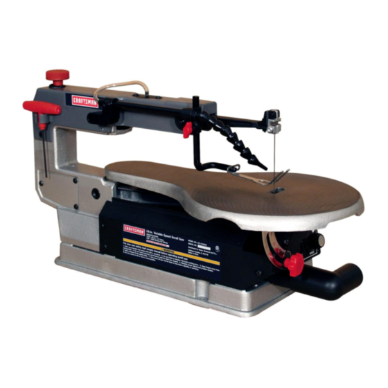
Operator's Manual
16 in. VARIABLE SPEED
SCROLL SAW
Model No. 137.216020
C
us
CAUTION:
Before using this Scroll Saw,
read this manual and follow
all its Safety Rules and
Operating Instructions
•
Safety Instructions
•
Installation
•
Operation
•
Maintenance
•
Parts List
Sears, Roebuck and Co., Hoffman Estates, IL 60179 USA
Visit our Craftsman website: www,sears,com/craftsman
Part No. 137216020001
Printed in China
Advertisement
Table of Contents

Related Manuals for Craftsman 21602 - 16 in. Variable Speed Scroll Saw


Summary of Contents for Craftsman 21602 - 16 in. Variable Speed Scroll Saw
- Page 1 Before using this Scroll Saw, • Operation read this manual and follow • Maintenance all its Safety Rules and • Parts List Operating Instructions Sears, Roebuck and Co., Hoffman Estates, IL 60179 USA Visit our Craftsman website: www,sears,com/craftsman Part No. 137216020001 Printed in China...
- Page 2 Parts List ....................CRAFTSMAN ONE YEAR FULL WARRANTY If this Craftsman tool fails due to a defect in material or workmanship within one year from the date of purchase, call 1-800-4-MY-HOME®to arrange for free repair (or replacement if repair proves impossible).
- Page 3 MOTOR Power Source ............. 1.6 A, 120 V AC, 60 Hz Speed Control ............. Electric TABLE Tilt ................45 o Left SAWDUST BLOWER ..........BLADE Speed ................400-1600 SPM Type ................Pin-end or Plain-end Length ................5 in. Depth of Throat ............16 in.
- Page 4 WARNING ICONS Your power tool and its Operator's Manual may contain "WARNING ICONS" (a picture symbol intended to alert you to, and/or instruct you how to avoid, a potentially hazardous condition). Understanding and heeding these symbols will help you operate your tool better and safer. Shown below are some of the symbols you may see.
- Page 5 GENERAL SAFETY INSTRUCTIONS KEEP CHILDREN AWAY. All BEFORE USING THIS POWER TOOL visitors and bystanders should be kept a safe distance from work Safety is a combination of common area. sense, staying alert and knowing how to use your power tool. MAKE WORKSHOP CHILD PROOF with padlocks, master WARNING J...
- Page 6 11. WEAR PROPER APPAREL. Do DISCONNECT TOOLS FROM not wear loose clothing, gloves, POWER SOURCE before servicing, neckties, rings, bracelets or other and when changing accessories jewelry which may get caught in such as blades, bits and cutters. moving parts. Nonslip footwear is recommended.
-
Page 7: Maintain Tools With Care
20.NEVER LEAVE THE TOOL RUNNING UNATTENDED. TURN THE POWER "OFF". Do not walk away from a running tool until the blade comes to a complete stop and the tool is unplugged from the power source. 21. DO NOT OVERREACH. Keep proper footing and balance at all times. -
Page 8: Read And Understand
READ AND UNDERSTAND YOUR SCROLL SAW MUST BE SECURELY FASTENED to safety instructions and operating a stand or workbench. If there procedures throughout the manual. is any tendency for the stand DO NOT OPERATE the Scroll Saw or workbench to move during until it is completely assembled operation, the stand or workbench MUST be fastened to the floor. -
Page 9: Check For Damaged Parts
TURN THE SAW OFF AND ALWAYS release blade tension UNPLUG THE CORD if the blade before loosening the blade holder screw. binds in the saw kerf while being backed out of the workpiece, usually caused by sawdust MAKE CERTAIN table tilting lock clogging the kerf. - Page 10 GROUNDING INSTRUCTIONS GUIDELINES FOR EXTENSION CORDS IN THE EVENT OF A MALFUNCTION OR BREAKDOWN, grounding provides USE THE PROPER EXTENSION a path of least resistance for electric CORD. Make sure your extension cord currents and reduces the risk of electric is in good condition.
- Page 11 themotor. T histoolis intended foruse Fig. 1 ona circuit t hathasa receptacle l ike Three-Pronged Plug theoneillustrated i n Fig.1. Fig.1 shows a three-pronged electrical Grounding Prong plugandreceptacle t hathasa Properly Grounded grounding c onductor. Ifa properly Three-Pronged Receptacle grounded receptacle i snotavailable, Fig.
-
Page 12: Available Accessories
AVAILABLE ACCESSORIES Supplied Not Supplied WARNING To avoid injury, do not attempt Adjustable Wrench to modify this tool or create accessories not recommended for use with this tool. Any such 3 mm T-Wrench alteration or modification is _,1.1 i.l.n,_ Combination Square misuse and could result in a hazardous condition leading to possible serious injury. -
Page 13: Unpacking And Checking
UNPACKING AND CHECKING 1. Remove the scroll saw from the CONTENTS carton by lifting the saw by the back of the upper frame. ,A WARNING 2. Place the saw on a secure To avoid injury, if any part is stationary work surface. missing or damaged, do not plug 3. - Page 14 Sawdust Blower T ubing Upper Arm T-Wrench T-Wrench H older Blade GuardFoot Worktable Blade GuardFoot LockKnob Blade Holder L ockScrew Sawdust Collection P ort Mounting Holes Bevel S cale TableLockKnob Tension Knob Bellows Seat Sawdust Blower Blade Storage ON/OFF Motor Variable Speed Mounting Holes Control K nob...
- Page 15 SCROLL SAW TERMS be used to remove the sawdust from under the table and base. BEVEL SCALE - Represents the degree of table angle from 0° to 45 ° TABLE LOCK KNOB - Securely locks when the table is tilted for bevel cutting. the table at the angle desired for bevel BLADE GUARD FOOT - Guards the cutting.
- Page 16 LEADING EDGE - The front edge of the workpiece that is guided into the blade. SAW BLADE PATH - Area or line of sight of the workpiece moving in line toward the saw blade edge. SURFACE - Top of workpiece being cut.
- Page 17 Estimated Assembly Time: 5-10 STORING THE T-WRENCH (FIG. B) minutes The left rear side of the body (1) has a U-Shaped clamp holder (2) designed WARNING to store the T-wrench (3). Position the To avoid injury, do not connect this shaft of the T-wrench handle into the scroll saw to the power source until U-shaped clamp holder as shown.
-
Page 18: Sawdust Collection
THE DUST BLOWER (FIG. D) Fig. E 1. Locate the sawdust blower tubing (1). 2. Connect the PVC plastic end of the tube to the bellows seat (2). 3. For best results, the dust blower tube should be adjusted to direct air at both the blade and the workpiece. -
Page 19: Installation
BLADE REMOVAL AND 2. Remove the blade (2) from the INSTALLATION upper (3) and lower (4) blade holder by pulling blade forward to release, PIN-END BLADE REMOVAL AND and lift the blade through the access INSTALLATION hole. (Fig. H) NOTE: WARNING Apply slight downward pressure To prevent personal injury, always... - Page 20 PIN-END BLADE INSTALLATION 3. Tighten the tension on the blade by (FIG. I, J, K) turning the tension knob clockwise NOTE: Do not tighten the set screw (1, (Fig. K). If the tension is too tight, turn counterclockwise. If too loose, 2) when using Pin-end blades.
- Page 21 PLAIN-END BLADEREMOVAL 3. Tilt the table to 0° and tighten the (FIG.L, M,N) table lock knob (7-Fig. N). Loosen 1. Loosen the tension on the blade the lower blade holder lock screw by turning the tension knob (5-Fig. M) under the table on the left counterclockwise.
-
Page 22: Bevel Stop Adjustment
2. Insert the new blade into the lower Fig. P blade holder slot (1), and then tighten the lower blade holder set screw (2). (Fig. O) 3. Tilt the table to the 0° bevel setting and lock the table lock knob. Fig. -
Page 23: Blade Guard Foot Adjustment
7. Tighten thelocknut(6). BLADE GUARD FOOT ADJUSTMENT 8. Whenthebladeis exactly 900 (FIG. S) (0 °)tothetable,loosen thebevel NOTE: User must keep constant indicator screw(9)using a Phillips downward pressure on workpiece when screwdriver. cutting. The blade guard foot is not 9. Adjust t hebevel i ndicator ( 10)to designed to hold down the workpiece, the"0"markonthebevel s caleand but is rather to help prevent the... - Page 24 SAWDUST BLOWER (FIG. S) Use this table as an example, but The sawdust blower (4) should be practice and your own personal positioned to point to the blade and preference will be the best selection method. workpiece to blow sawdust out of the line-of-sight when cutting.
- Page 25 General S croll S awBlade Reference G uide Tooth Speed -_- Application Type Faster Slower Standard 9.5- 48 General cutting Skip 9.5~ 33 Better c hipremoval. Smooth, splinterless f inish Double 10_ 37 Efficient chipremoval. Cleanedges Reverse Eliminates u nderside t earout. S mooth, ..
- Page 26 VARIABLE SPEED CONTROL AND OVERLOAD BREAKER (FIG. U) ON/OFF SWITCH When the motor in overload during operation, the overload breaker will cause the motor to stop automatically ,_ WARNING For your own safety, always push to prevent damage to the motor. Push the switch "OFF"...
- Page 27 canonlyremove woodwhenthey 11.Thissawuses5 in.longpinorplain areonthedownstroke. endtypeblades only. 4. Thereis a learning curveforeach 12.Blades wearfasterwhencutting person whowants to usethis plywood or particle board which saw.During thatperiodoftimeit is veryabrasive. Angle cuttingin hardwoods r educes bladetoothset isexpected t hatsomeblades will fasterduetothebladedeflection. break untilyoulearn howto use thesawandreceive thegreatest benefit f romtheblades.
-
Page 28: Cutting Operation
6. When turning the scroll saw ON, Left Bevel Cutting (Fig. W) position the workpiece against scrap Bevel cuts up to 45 degrees to the left wood prior to touching the leading are possible on this unit. edge of the workpiece against the 1. -
Page 29: Rip Or Straight Line Cutting
RIP OR STRAIGHT LINE CUTTING saw ON. Set the desired speed by (FIG. X) turning the control knob clockwise or counterclockwise. ,A WARNING CAUTION: In order to avoid To avoid injury from an accidental uncontrollable lifting of the workpiece starting, make sure the switch is and reduce blade breakage, do not in the OFF position and the plug is turn saw ON while the workpiece is... - Page 30 INTERIOR CUTTING (FIG. Y) 1. Lay out the design on the workpiece (1). Drill a 1/4 in. hole (4) in the workpiece. 2. Remove the blade by turning the tension knob (2) counterclockwise. Refer to BLADE REMOVAL AND INSTALLATION. 3. Place the workpiece on the saw table with the workpiece hole (4) over the access hole in the table (5).
-
Page 31: Replacing Carbon Brushes
into. Tighten the cap snugly, but do not _lk WARNING overtighten. For your own safety, turn the switch NOTE: When reinstalling the same OFF and remove the plug from the brushes, put them back in the way they power source before maintaining came out. - Page 32 WARNING To avoid injury from accidental starting, always turn switch OFF and unplug the tool before moving, replacing the blade or making adjustments. PROBLEM PROBLEM CAUSE REMEDY SUGGESTED Breaking blades 1. Wrong tension. 1. Adjust blade tension. See BLADE REMOVAL AND INSTALLATION 2.
- Page 34 16 in. VARIABLE SPEED SCROLL SAW MODEL NO. 137.216020 WARNING When servicing use only CRAFTSMAN replacement parts. Use of any other parts many create a HAZARD or cause product damage. Any attempt to repair or replace electrical parts on this Scroll Saw may create a HAZARD unless repair is done by a qualified service technician.
- Page 35 2SUL 2TID OJTF OJU4_ OJUK r/OZ9F2 OHFX 0EQS 2SUN 2SUp 2SLK lOAN% "4 OKOW 3 OKI%_...
- Page 36 Your Home For expert troubleshooting and home solutions advice: www.managemyhome.com For repair - in your home - of all major brand appliances, lawn and garden equipment, or heating and cooling systems, no matter who made it, no matter who sold it! For the replacement parts, accessories and owner's manuals that you need to do-it-yourself.