Table of Contents
Advertisement
Advertisement
Table of Contents

Related Manuals for Asus F1A75-M LE


Summary of Contents for Asus F1A75-M LE
- Page 1 F1A75-M LE...
- Page 2 Product warranty or service will not be extended if: (1) the product is repaired, modified or altered, unless such repair, modification of alteration is authorized in writing by ASUS; or (2) the serial number of the product is defaced or missing.
-
Page 3: Table Of Contents
Contents Notices ......................vi Safety information ..................vii About this guide ..................viii F1A75-M LE specifications summary ............ix Chapter 1: Product introduction Welcome! ..................1-1 Package contents ................. 1-1 Special features ................1-1 1.3.1 Product highlights ............1-1 Before you proceed ..............1-4 Motherboard overview .............. - Page 4 Managing and updating your BIOS ..........2-1 2.1.1 ASUS Update utility ............2-1 2.1.2 ASUS EZ Flash 2 ............2-2 2.1.3 ASUS CrashFree BIOS 3 utility ........2-3 2.1.4 ASUS BIOS Updater ............2-4 BIOS setup program ..............2-7 Main menu .................. 2-11 2.3.1 System Language [English] ...........2-11...
- Page 5 Setup Mode [EZ Mode] ..........2-25 2.7.6 Boot Option Priorities ............ 2-25 2.7.7 Boot Override ..............2-25 Tools menu ................. 2-26 2.8.1 ASUS EZ Flash 2 Utility ..........2-26 2.8.2 ASUS O.C. Profile ............2-26 2.8.3 ASUS SPD Information ..........2-26 Exit menu ..................2-27...
-
Page 6: Notices
This class B digital apparatus complies with Canadian ICES-003. ASUS Recycling/Takeback Services ASUS recycling and takeback programs come from our commitment to the highest standards for protecting our environment. We believe in providing solutions for you to be able to responsibly recycle our products, batteries, other components as well as the packaging materials. -
Page 7: Safety Information
Complying with the REACH (Registration, Evaluation, Authorisation, and Restriction of Chemicals) regulatory framework, we published the chemical substances in our products at ASUS REACH website at http://csr.asus.com/english/REACH.htm. DO NOT throw the motherboard in municipal waste. This product has been designed to enable proper reuse of parts and recycling. -
Page 8: About This Guide
Refer to the following sources for additional information and for product and software updates. ASUS websites The ASUS website provides updated information on ASUS hardware and software products. Refer to the ASUS contact information. Optional documentation Your product package may include optional documentation, such as warranty flyers, that may have been added by your dealer. -
Page 9: F1A75-M Le Specifications Summary
ECC DDR3 1866 /1600/ 1333/ 1066 MHz memory modules The maximum 32GB memory capacity can be supported with 16GB or above DIMMs. ASUS will update the memory QVL once the DIMMs are available in the market. ** Refer to www.asus.com for the latest Memory QVL (Qualified Vendors List). - Page 10 - Industry leading 4+2 Phase Power Design ASUS Exclusive Features - AI Suite II - AI Charger - Anti-Surge Protection - ASUS UEFI BIOS EZ Mode featuring user-friendly graphics interface ASUS Quiet Thermal Solutions - ASUS Fanless Design: Stylish heatsink solution - ASUS Fan Xpert...
- Page 11 F1A75-M LE specifications summary Back Panel I/O ports 1 x PS/2 keyboard port 1 x PS/2 mouse port 1 x DVI-D output port 1 x D-Sub output port 1 x LAN (RJ-45) port 4 x USB 2.0/1.1 ports 2 x USB 3.0 ports (blue)
-
Page 13: Chapter 1: Product Introduction
® The motherboard delivers a host of new features and latest technologies, making it another standout in the long line of ASUS quality motherboards! Before you start installing the motherboard, and hardware devices on it, check the items in your package with the list below. -
Page 14: Asus Exclusive Features
• The actual charging speed may vary with your USB device’s conditions. ASUS UEFI BIOS (EZ Mode) The new ASUS UEFI BIOS is an Unified Extensible Firmware Interface that offers a user-friendly interface that goes beyond traditional keyboard- only BIOS controls to enable more flexible and convenient mouse input. -
Page 15: Asus Mylogo 2
ASUS EZ Flash 2 ASUS EZ Flash 2 is a user-friendly utility that allows you to update the BIOS without using a bootable floppy disk or an OS-based utility. ASUS MyLogo 2™... -
Page 16: Before You Proceed
ErP requires products to meet certain energy efficiency requirements in regards to energy consumptions. This is in line with ASUS vision of creating environment-friendly and energy-efficient products through product design and innovation to reduce carbon footprint of the product and thus mitigate environmental impacts. -
Page 17: Motherboard Overview
Screw holes Place six screws into the holes indicated by circles to secure the motherboard to the chassis. DO NOT overtighten the screws! Doing so can damage the motherboard. Place this side towards the rear of the chassis. ASUS F1A75-M LE... -
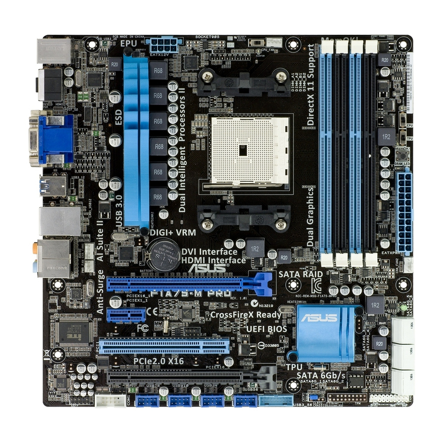
Page 18: Motherboard Layout
1.5.3 Motherboard layout 1.5.4 Layout contents Connectors/Jumpers/Slots/LED Page Connectors/Jumpers/Slots/LED Page ATX power connectors (24-pin EATXPWR, 1-18 Speaker connector (4-pin SPEAKER) 1-17 4-pin ATX12V) Power, CPU and chassis fan connectors 1-17 10. USB 3.0 connector (20-1 pin USB3_34) 1-22 (3-pin PWR_FAN, 4-pin CPU_FAN, and 4-pin CHA_FAN) AMD FM1 socket 11. -
Page 19: Accelerated Processing Unit (Apu)
Carefully insert the APU into the socket until it fits in place. The APU fits only in one correct orientation. DO NOT force the APU into the socket to prevent bending the pins and damaging the APU! Small triangle Gold triangle ASUS F1A75-M LE... - Page 20 When the APU is in place, push down the socket lever to secure the APU. The lever clicks on the side tab to indicate that it is locked. Install a APU heatsink and fan following the instructions that comes with the heatsink package. You can also refer to section 1.6.2 Installing heatsink and fan for instructions.
-
Page 21: Installing The Heatsink And Fan
Your boxed CPU heatsink and fan assembly should come with installation instructions for the CPU, heatsink, and the retention mechanism. If the instructions in this section do not match the CPU documentation, follow the latter. Attach one end of the retention bracket to the retention module base. ASUS F1A75-M LE... -
Page 22: System Memory
Align the other end of the retention bracket to the retention module base. A clicking sound denotes that the retention bracket is in place. Ensure that the fan and heatsink assembly perfectly fits the retention mechanism module base, otherwise you cannot snap the retention bracket in place. Push down the retention bracket lock on the retention mechanism to secure the heatsink and fan to the module base. -
Page 23: Memory Configurations
• The maximum 32GB memory capacity can be supported with 16GB or above DIMMs. ASUS will update the memory QVL once the DIMMs are available in the market. • The default memory operation frequency is dependent on its Serial Presence Detect (SPD), which is the standard way of accessing information from a memory module. -
Page 24: Installing A Dimm
1.7.3 Installing a DIMM Unplug the power supply before adding or removing DIMMs or other system components. Failure to do so can cause severe damage to both the motherboard and the components. Press the retaining clips outward to DIMM notch unlock a DIMM socket. -
Page 25: Expansion Slots
This motherboard supports PCI Express x1 network cards, SCSI cards, and other cards that comply with the PCI Express specifications. 1.8.5 PCI Express x16 slots This motherboard supports two PCI Express x16 graphics cards that comply with the PCI Express specifications. ASUS F1A75-M LE 1-13... -
Page 26: Jumpers
PCI Express operating mode VGA configuration PCIe x16_1 PCIe x16_2 Single VGA/PCIe card x16 (Recommended for single VGA card) Dual VGA/PCIe card • In single VGA card mode, use the PCIe 2.0 x16_1 slot (blue) for a PCI Express x16 graphics card to get better performance. -
Page 27: Connectors
Front Speaker Out Front Speaker Out Pink Mic In Mic In Mic In Mic In Orange – – Center/Subwoofer Center/Subwoofer Black – Rear Speaker Out Rear Speaker Out Rear Speaker Out Gray – – – Side Speaker Out ASUS F1A75-M LE 1-15... - Page 28 USB 2.0 ports 1 and 2. These two 4-pin Universal Serial Bus (USB) ports are for USB 2.0/1.1 devices. USB 3.0 ports 1 and 2. These two 9-pin Universal Serial Bus (USB) ports are for USB 3.0 devices. • DO NOT connect a keyboard / mouse to any USB 3.0 port when installing Windows ®...
-
Page 29: Internal Connectors
• The CPU_FAN connector supports a CPU fan of maximum 2A (24 W) fan power. • Only the CPU_FAN and CHA_FAN connectors support the ASUS Fan Xpert feature. • If you install two VGA cards, we recommend that you plug the rear chassis fan cable to the motherboard connector labeled CHA_FAN for better thermal environment. - Page 30 The system may become unstable or may not boot up if the power is inadequate. • If you are uncertain about the minimum power supply requirement for your system, refer to the Recommended Power Supply Wattage Calculator at http://support.asus. com/PowerSupplyCalculator/PSCalculator.aspx?SLanguage=en-us for details. 1-18...
- Page 31 This connector is for a serial (COM) port. Connect the serial port module cable to this connector, then install the module to a slot opening at the back of the system chassis. The COM module is purchased separately. ASUS F1A75-M LE 1-19...
- Page 32 System panel connector (10-1 pin F_PANEL) This connector supports several chassis-mounted functions. • System power LED (2-pin PLED) This 2-pin connector is for the system power LED. Connect the chassis power LED cable to this connector. The system power LED lights up when you turn on the system power, and blinks when the system is in sleep mode.
- Page 33 • If you want to connect a high definition front panel audio module to this connector, set the Front Panel Type item in the BIOS to [HD]. See section 2.5.5 Onboard Devices Configuration for details. • The front panel audio I/O module is purchased separately. ASUS F1A75-M LE 1-21...
- Page 34 This connector is for the additional USB 3.0 ports. Connect the USB 3.0 bracket cable to this connector, then install the USB 3.0 bracket to the rear side of the chassis. If your chassis support customized front panel installation, with ASUS USB 3.0 header, you can have a front panel USB 3.0 solution.
-
Page 35: Software Support
The contents of the Support DVD are subject to change at any time without notice. Visit the ASUS website at www.asus.com for updates. To run the Support DVD Place the Support DVD into the optical drive. - Page 36 1-24 Chapter 1: Product introduction...
-
Page 37: Chapter 2: Bios Information
BIOS in the future. Copy the original motherboard BIOS using the ASUS Update utility. 2.1.1 ASUS Update utility The ASUS Update is a utility that allows you to manage, save, and update the motherboard BIOS in Windows environment. ®... -
Page 38: Asus Ez Flash 2
Follow the onscreen instructions to complete the updating process. 2.1.2 ASUS EZ Flash 2 The ASUS EZ Flash 2 feature allows you to update the BIOS without using an OS-based utility. Before you start using this utility, download the latest BIOS file from the ASUS website at www.asus.com. -
Page 39: Asus Crashfree Bios 3 Utility
2.1.3 ASUS CrashFree BIOS 3 utility The ASUS CrashFree BIOS 3 is an auto recovery tool that allows you to restore the BIOS file when it fails or gets corrupted during the updating process. You can restore a corrupted BIOS file using the motherboard support DVD or a USB flash drive that contains the updated BIOS file. -
Page 40: Asus Bios Updater
2.1.4 ASUS BIOS Updater The ASUS BIOS Updater allows you to update BIOS in DOS environment. This utility also allows you to copy the current BIOS file that you can use as a backup when the BIOS fails or gets corrupted during the updating process. - Page 41 The BIOS Updater backup screen appears indicating the BIOS backup process. When BIOS backup is done, press any key to return to the DOS prompt. ASUSTek BIOS Updater for DOS V1.07 Current ROM Update ROM BOARD: F1A75-M LE BOARD: Unknown VER: 0302 VER:...
-
Page 42: Updating The Bios File
Select the Load Optimized Defaults item under the Exit menu. Refer to section 2.9 Exit menu for details. • Ensure to connect all SATA hard disk drives after updating the BIOS file if you have disconnected them. ASUS F1A75-M LE... -
Page 43: Bios Setup Program
BIOS setup program Use the BIOS Setup program to update the BIOS or configure its parameters. The BIOS screens include navigation keys and brief online help to guide you in using the BIOS Setup program. Entering BIOS Setup at startup To enter BIOS Setup at startup: •... -
Page 44: Bios Menu Screen
Selects the boot device priority Normal mode ASUS Optimal mode Displays the system properties of the selected mode on the right hand side The boot device options vary depending on the devices you installed to the system. ASUS F1A75-M LE... -
Page 45: Advanced Mode
The Advanced Mode provides advanced options for experienced end-users to configure the BIOS settings. The figure below shows an example of the Advanced Mode. Refer to the following sections for the detailed configurations. To access the EZ Mode, click Exit, then select ASUS EZ Mode. Back button Menu items... -
Page 46: Menu Items
You cannot select an item that is not user-configurable. A configurable field is highlighted when selected. To change the value of a field, select it and press <Enter> or click on it to display a list of options. 2-10 ASUS F1A75-M LE... -
Page 47: Main Menu
Main menu The Main menu screen appears when you enter the Advanced Mode of the BIOS Setup program. The Main menu provides you an overview of the basic system information, and allows you to set the system date, time, language, and security settings. EFI BIOS Utility - Advanced Mode Exit Main... -
Page 48: Administrator Password
To clear the user password, follow the same steps as in changing a user password, but press <Enter> when prompted to create/confirm the password. After you clear the password, the User Password item on top of the screen shows Not Installed. 2-12 ASUS F1A75-M LE... -
Page 49: Ai Tweaker Menu
Ai Tweaker menu The Ai Tweaker menu items allow you to configure overclocking-related items. Be cautious when changing the settings of the Ai Tweaker menu items. Incorrect field values can cause the system to malfunction. The configuration options for this section vary depending on the CPU and DIMM model you installed on the motherboard. -
Page 50: Ai Overclock Tuner [Auto]
Saving Mode] [Medium Power Saving Mode] [Max Power Saving Mode] 2.4.5 OC Tuner OC Tuner automatically overclocks the frequency and voltage of CPU and DRAM for enhancing the system performance. Press <Enter> and select OK to start automatic overclocking. 2-14 ASUS F1A75-M LE... -
Page 51: Dram Timing Control
2.4.6 DRAM Timing Control The sub-items in this menu allow you to set the DRAM timing control features. Use the <+> and <-> keys to adjust the value. To restore the default setting, type [auto] using the keyboard and press <Enter>. Changing the values in this menu may cause the system to become unstable! If this happens, revert to the default settings. -
Page 52: Apu1.2V Voltage [Auto]
This item allows you to set this function for better system performance. Configuration options: [Auto] [Disabled] [Enabled] The actual performance boost may vary depending on your CPU specification. 2.4.14 APU Spread Spectrum [Auto] [Auto] Automatic configuration. [Disabled] Enhances the PCIE overclocking ability. [Enabled] Sets to [Enabled] for EMI control. 2-16 ASUS F1A75-M LE... -
Page 53: Advanced Menu
Advanced menu The Advanced menu items allow you to change the settings for the CPU and other system devices. Be cautious when changing the settings of the Advanced menu items. Incorrect field values can cause the system to malfunction. EFI BIOS Utility - Advanced Mode Exit Main Ai Tweaker... -
Page 54: Sata Configuration
S.M.A.R.T. Status Check [Enabled] S.M.A.R.T. (Self-Monitoring, Analysis and Reporting Technology) is a monitor system. When read/write of your hard disk errors occur, this feature allows the hard disk to report warning messages during the POST. Configuration options: [Enabled] [Disabled] 2-18 ASUS F1A75-M LE... -
Page 55: Usb Configuration
2.5.3 USB Configuration The items in this menu allow you to change the USB-related features. The USB Devices item shows the auto-detected values. If no USB device is detected, the item shows None. Legacy USB Support [Enabled] [Enabled] Enables the support for USB devices on legacy operating systems (OS). [Disabled] The USB devices can be used only for the BIOS setup program. -
Page 56: Onboard Devices Configuration
Parallel Port [Enabled] Allows you to enable or disable the parallel port (LPT/LPTE). Configuration options: [Enabled] [Disabled] Change Settings [Auto] Allows you to select the Parallel Port base address. Configuration options: [IO=378h; IRQ=5] [IO=378h; IRQ=5,6,7,9,10,11,12] [IO=278h; IRQ=5,6,7,9,10,11,12] 2-20 ASUS F1A75-M LE... -
Page 57: Apm
Device Mode [Auto] Allows you to set the Printer port mode. Configuration options: [Standard Parallel Port Mode] [EPP Mode] [ECP Mode] [EPP Mode & ECP Mode] 2.5.6 Restore AC Power Loss [Power Off] [Power On] The system goes into on state after an AC power loss. [Power Off] The system goes into off state after an AC power loss. -
Page 58: Monitor Menu
This item appears only when you enable the CPU Q-Fan Control feature and allows you to disable or set the CPU fan warning speed. Configuration options: [Ignore] [200RPM] [300 RPM] [400 RPM] [500 RPM] [600 RPM] 2-22 ASUS F1A75-M LE... -
Page 59: Cpu Voltage, 3.3V Voltage, 5V Voltage, 12V Voltage
CPU Fan Profile [Standard] This item appears only when you enable the CPU Q-Fan Control feature and allows you to set the appropriate performance level of the CPU fan. [Standard] Sets to [Standard] to make the CPU fan automatically adjust depending on the CPU temperature. -
Page 60: Boot Menu
[Disabled] Disables the full screen logo display feature. Set this item to [Enabled] to use the ASUS MyLogo 2™ feature. Post Report [5 sec] This item appears only when the Full Screen Logo item is set to [Disabled] and allows you to set the waiting time for the system to display the post report. -
Page 61: Option Rom Messages [Force Bios]
• To select the boot device during system startup, press <F8> when ASUS Logo appears. • To access Windows OS in Safe Mode, press <F8> after POST. -
Page 62: Tools Menu
> ASUS SPD Information 2.8.1 ASUS EZ Flash 2 Utility Allows you to run ASUS EZ Flash 2. Press [Enter] to launch the ASUS EZ Flash 2 screen. For more details, see section 2.1.2 ASUS EZ Flash 2. 2.8.2 ASUS O.C. Profile This item allows you to store or load multiple BIOS settings. -
Page 63: Exit Menu
Load Optimized Defaults Save Changes & Reset Discard Changes & Exit ASUS EZ Mode Launch EFI Shell from filesystem device Load Optimized Defaults This option allows you to load the default values for each of the parameters on the Setup menus. - Page 64 2-28 ASUS F1A75-M LE...
-
Page 65: Asus Contact Information
+1-510-739-3777 +1-510-608-4555 Web site usa.asus.com Technical Support Telephone +1-812-282-2787 Support fax +1-812-284-0883 Online support support.asus.com ASUS COMPUTER GmbH (Germany and Austria) Address Harkort Str. 21-23, D-40880 Ratingen, Germany +49-2102-959911 Web site www.asus.de Online contact www.asus.de/sales Technical Support Telephone (Component) +49-1805-010923*...