Table of Contents
Advertisement
Advertisement
Table of Contents

Related Manuals for Asus M5A97 LE R2.0


Summary of Contents for Asus M5A97 LE R2.0
- Page 1 M5A97 LE R2.0...
- Page 2 Product warranty or service will not be extended if: (1) the product is repaired, modified or altered, unless such repair, modification of alteration is authorized in writing by ASUS; or (2) the serial number of the product is defaced or missing.
-
Page 3: Table Of Contents
DIP (Dual Intelligent Processors) - TPU (TurboV Processing Unit) & ..........1-2 EPU (Energy Processing Unit) 1.1.3 ASUS Exclusive Features ............1-2 1.1.4 ASUS Quiet Thermal Solution ............. 1-3 1.1.5 ASUS EZ DIY ................1-3 1.1.6 Other special features ..............1-4 Motherboard overview ................1-5 1.2.1... - Page 4 Network Stack ................3-21 Monitor menu ................... 3-22 Boot menu ....................3-25 Tools menu ....................3-27 3.8.1 ASUS EZ Flash 2 Utility ............3-27 3.8.2 ASUS SPD Information ............. 3-27 3.8.3 ASUS O.C. Profile ..............3-27 Exit menu ....................3-28 3.10...
- Page 5 Requirements ................6-1 6.1.2 Before you begin ................. 6-1 6.1.3 Installing two CrossFireX™ graphics cards ........ 6-2 6.1.4 Installing the device drivers ............6-3 6.1.5 Enabling the AMD CrossFireX™ technology ......6-3 ® Appendices Notices ........................A-1 ASUS contact information ..................A-4...
-
Page 6: Safety Information
Safety information Electrical safety • To prevent electrical shock hazard, disconnect the power cable from the electrical outlet before relocating the system. • When adding or removing devices to or from the system, ensure that the power cables for the devices are unplugged before the signal cables are connected. If possible, disconnect all power cables from the existing system before you add a device. -
Page 7: About This Guide
Refer to the following sources for additional information and for product and software updates. ASUS websites The ASUS website provides updated information on ASUS hardware and software products. Refer to the ASUS contact information. Optional documentation Your product package may include optional documentation, such as warranty flyers, that may have been added by your dealer. -
Page 8: Conventions Used In This Guide
Conventions used in this guide To ensure that you perform certain tasks properly, take note of the following symbols used throughout this manual. DANGER/WARNING: Information to prevent injury to yourself when trying to complete a task. CAUTION: Information to prevent damage to the components when trying to complete a task IMPORTANT: Instructions that you MUST follow to complete a task. -
Page 9: M5A97 Le R2.0 Specifications Summary
3GB system memory if you are using a Windows 32-bit operating ® system. • Refer to www.asus.com for the latest Memory QVL (Qualified Vendors List). Expansion slots 2 x PCIe 2.0 x16 slots (Blue @x16 speed, Black @x4 speed) 2 x PCIe 2.0 x1 slots... - Page 10 - EPU ASUS TPU - Auto Tuning, TurboV ASUS Exclusive Features - ASUS UEFI BIOS EZ Mode featuring friendly graphics user interface - ASUS USB 3.0 Boost - ASUS Network iControl - ASUS AI Suite II - ASUS Ai Charger+...
- Page 11 1 x COM connector BIOS 64Mb Flash ROM, UEFI BIOS, PnP, DMI 2.0, WfM 2.0, SM BIOS 2.7, ACPI 2.0a Multi-language BIOS, ASUS EZ Flash 2, F12 PrintScreen, F3 Shortcut Function and ASUS DRAM SPD (Serieal Presence Detect) memory information Manageability WfM 2.0, DMI 2.0, WOL by PME, WOR by PME, PXE...
-
Page 12: Package Contents
Package contents Check your motherboard package for the following items. M5A97 LE R2.0 ASUS M5A97 LE R2.0 motherboard User Guide Support DVD 2 x Serial ATA 6.0 Gb/s cables 1 x ASUS I/O Shield • If any of the above items is damaged or missing, contact your retailer. -
Page 13: Installation Tools And Components
Installation tools and components 1 bag of screws Philips (cross) screwdriver PC chassis Power supply unit AMD AM3+ CPU AMD AM3+ compatible CPU Fan DIMM SATA hard disk drive SATA optical disc drive (optional) Graphics card (optional) The tools and components in the table above are not included in the motherboard package. xiii... -
Page 15: Product Introduction
Product introduction Special features 1.1.1 Product highlights FX™Series/Phenom™ II/Athlon™ II/Sempron™ 100 series CPU support ® This motherboard supports AMD Socket AM3+ multi-core processors with unique L3 ® cache and delivers better overclocking capabilities with less power consumption. It features dual-channel DDR3 memory support and accelerates data transfer rate up to 4800MT/s via HyperTransport™... -
Page 16: Dip (Dual Intelligent Processors) - Tpu (Turbov Processing Unit)
ASUS TurboV With its user-friendly interface, ASUS TurboV offers you the adrenaline rush of real-time overclocking without exiting or rebooting the OS. It also provides you with the ASUS OC profiles for the best overclocking settings in different scenarios. Auto Tuning Auto Tuning is an intelligent tool that automates overclocking to achieve a total system level up. -
Page 17: Asus Quiet Thermal Solution
ASUS DRAM SPD (Serial Presence Detect) information detecting faulty DIMMs, and helping with difficult POST situations. ASUS EZ-Flash 2 ASUS EZ Flash 2 is a user-friendly utility that allows you to update the BIOS without using a bootable floppy disk or an OS-based utility. Ai Charger+ ASUS Ai Charger+, the latest Ai Charger* version, brings you to a new level of USB3.0 fast... -
Page 18: Other Special Features
CPU parameters to their default settings. ASUS O.C. Profile The motherboard features the ASUS O.C. Profile that allows you to conveniently store or load multiple BIOS settings. The BIOS settings can be stored in the CMOS or a separate file, giving you the freedom to share and distribute your favorite settings. -
Page 19: Motherboard Overview
Motherboard overview 1.2.1 Before you proceed Take note of the following precautions before you install motherboard components or change any motherboard settings. • Unplug the power cord from the wall socket before touching any component. • Before handling components, use a grounded wrist strap or touch a safely grounded object or a metal object, such as the power supply case, to avoid damaging them due to static electricity. -
Page 20: Motherboard Layout
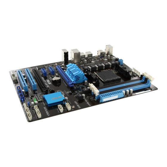
1.2.2 Motherboard layout 22.9cm(9.0in) KBMS CHA_FAN2 CPU_FAN CHA_FAN3 ATX12V USB3_12 1042 USB56 USB34 LAN_USB12 CHA_FAN1 AUDIO ® PCIEX16_1 8111F PCIEX1_1 Lithium Cell CMOS Power SATA6G_6 Super PCIEX1_2 64Mb SATA6G_5 M5A97 LE R2.0 ® BIOS SB950 PCIEX16_2 PCI1 SATA6G_2 SATA6G_4 PCI2 CLRTC SPDIF_OUT SATA6G_1 SATA6G_3... -
Page 21: Layout Contents
Layout contents Connectors/Jumpers/Slots/LED Page 1. CPU and chassis fan connectors (4-pin CPU_FAN and 4-pin CHA_FAN1/2/3) 1-20 2. ATX power connectors (24-pin EATXPWR, 4-pin ATX12V) 1-22 3. AMD AM3+ CPU socket 4. DDR3 DIMM slots 5. SATA 6.0Gb/s connectors (7-pin SATA6G_1~6) 1-19 6. -
Page 22: Central Processing Unit (Cpu)
1.2.3 Central Processing Unit (CPU) The motherboard comes with an AM3+/AM3 socket designed for AMD FX™ Series/ ® Phenom™ II/Athlon™ II/Sempron™ 100 Series Processors. M5A97 LE R2.0 M5A97 LE R2.0 CPU socket AM3+ Ensure that all power cables are unplugged before installing the CPU. The AM3+ socket has a different pinout from the 940-pin socket designed for the AMD Opteron processor. -
Page 23: System Memory
1.2.4 System memory The motherboard comes with four Double Data Rate 3 (DDR3) Dual Inline Memory Modules (DIMM) slots. A DDR3 module is notched differently from a DDR or DDR2 module. DO NOT install a DDR or DDR2 memory module to the DDR3 slot. M5A97 LE R2.0 M5A97 LE R2.0 240-pin DDR3 DIMM sockets Recommended memory configurations... -
Page 24: Memory Configurations
• For system stability, use a more efficient memory cooling system to support a full memory load (4 DIMMs) or overclocking condition. • Visit the ASUS website at www.asus.com for the latest QVL. 1-10 Chapter 1: Product introduction... - Page 25 M5A97 LE R2.0 Motherboard Qualified Vendors Lists (QVL) DDR3 2133(O.C.) MHz capability DIMM socket support Chip Chip (Optional) Vendors Part No. Size Timing Voltage Brand 1 DIMM 2 DIMMs Apacer 78.BAGE4.AFD0C(XMP) 8GB (2x 4GB ) 9-9-9-24 • CORSAIR CMT4GX3M2A2133C9(XMP) 4GB (2x 2GB ) 9-10-9-24 1.65 •...
- Page 26 DDR3 1800 MHz capability DIMM socket support Chip Chip (Optional) Vendors Part No. Size Timing Voltage Brand 1 DIMM 2 DIMMs G.SKILL F3-14400CL9D-4GBBRL(XMP) 4GB ( 2x 2GB ) 9-9-9-24 1.65 • • DDR3 1600 MHz capability DIMM socket support (Optional) Chip Vendors Part No.
- Page 27 DDR3 1333 MHz capability DIMM socket support (Optional) Chip Vendors Part No. Size Chip NO. Timing Voltage Brand 1 DIMM DIMMs DIMMs 1.25~ A-DATA AXDU1333GC2G9(XMP) SS - 9-9-9-24 • • • 1.35 A-DATA AD63I1C1624EV DS A-DATA 3CCA-1509A • • • A-DATA SU3U1333W8G9(XMP) DS ELPIDA...
- Page 28 (4) Supports four (4) modules inserted into both the blue and black slots as two pairs of Dual-channel memory configuration. • When overclocking, some AMD CPU models may not support DDR3 1600 or higher frequency DIMMS. • Visit the ASUS website for the latest QVL. 1-14 Chapter 1: Product introduction...
-
Page 29: Expansion Slots
1.2.5 Expansion slots Unplug the power cord before adding or removing expansion cards. Failure to do so may cause you physical injury and damage motherboard components. M5A97 LE R2.0 Slot No. Slot Description PCIe 2.0 x16_1 slot [Blue] (at x16 speed) PCIe 2.0 x1_1 slot PCIe 2.0 x1_2 slot PCIe 2.0 x16_2 slot [Black] (at x4 speed) -
Page 30: Irq Assignments For This Motherboard
• In single VGA card mode, use the PCIe 2.0 x16_1 slot (navy blue) for a PCI Express x16 graphics card to get better performance. • We recommend that you provide sufficient power when running CrossFireX™. • Connect a chassis fan to the motherboard connector labeled CHA_FAN1/2/3 when using multiple graphics cards for better thermal environment. -
Page 31: Clear Rtc Ram
1.2.6 Jumpers Clear RTC RAM (CLRTC) This jumper allows you to clear the Real Time Clock (RTC) RAM in CMOS. You can clear the CMOS memory of date, time, and system setup parameters by erasing the CMOS RTC RAM data. The onboard button cell battery powers the RAM data in CMOS, which include system setup information such as system passwords. -
Page 32: Onboard Leds
1.2.7 Onboard LEDs Standby Power LED The motherboard comes with a standby power LED that lights up to indicate that the system is ON, in sleep mode, or in soft-off mode. This is a reminder that you should shut down the system and unplug the power cable before removing or plugging in any motherboard component. -
Page 33: Internal Connectors
1.2.8 Internal connectors Serial ATA 6.0 Gb/s connectors (7-pin SATA6G 1~6) These connectors are for the Serial ATA 6.0 Gb/s signal cables for Serial ATA hard disk drives and optical disc drives. If you installed Serial ATA hard disk drives, you can create a RAID 0, RAID 1, RAID 5, RAID 10, or JBOD configuration through the onboard controller. -
Page 34: Usb 2.0/Cpu/Chassis Fan Connectors
• The CPU_FAN connector supports a CPU fan of maximum 1A (12 W) fan power. • Only the CPU_FAN and CHA_FAN1/2/3 connectors support the ASUS Fan Xpert feature. • If you install two VGA cards, we recommend that you plug the rear chassis fan cable to the motherboard connector labeled CHA_FAN1/2 for better thermal environment. -
Page 35: Digital Audio Connector
Digital audio connector (4-1 pin SPDIF_OUT) This connector is for an additional Sony/Philips Digital Interface (S/PDIF) port. M5A97 LE R2.0 SPDIF_OUT M5A97 LE R2.0 Digital audio connector Ensure that the audio device of Sound playback is Realtek High Definition Audio (the name may be different based on the OS). - Page 36 • If you are uncertain about the minimum power supply requirement for your system, refer to the Recommended Power Supply Wattage Calculator at http://support.asus. com/PowerSupplyCalculator/PSCalculator.aspx?SLanguage=en-us for details. • If you want to use two high-end PCI Express x16 cards, use a PSU with 1000W power or above to ensure the system stability.
-
Page 37: Serial Port Connector
Serial port connector (10-1 pin COM1) This connector is for a serial (COM) port. Connect the serial port module cable to this connector, then install the module to a slot opening at the back of the system chassis. COM1 PIN 1 M5A97 LE R2.0 M5A97 LE R2.0 Serial port (COM1) connector The COM module is purchased separately. -
Page 38: System Panel Connector
System panel connector (20-8 pin PANEL) This connector supports several chassis-mounted functions. PLED SPEAKER PANEL PIN 1 M5A97 LE R2.0 IDE_LED PWRSW RESET * Requires an ATX power supply M5A97 LE R2.0 System panel connector • System power LED (2-pin PLED) This 2-pin connector is for the system power LED. -
Page 39: Basic Installation
The diagrams in this section are for reference only. The motherboard layout may vary with models, but the installation steps are the same for all models. Install the ASUS I/O Shield to the chassis rear I/O panel. ASUS M5A97 LE R2.0... - Page 40 Place the motherboard into the chassis, ensuring that its rear I/O ports are aligned to the chassis’ rear I/O panel. Chapter 2: Getting started...
- Page 41 Place six screws into the holes indicated by circles to secure the motherboard to the chassis. M5A97 LE R2.0 DO NOT overtighten the screws! Doing so can damage the motherboard. ASUS M5A97 LE R2.0...
-
Page 42: Cpu Installation
2.1.2 CPU installation The AMD AM3+ socket is compatible with AMD AM3+ and AM3 processors. Ensure you use a CPU designed for the AM3+ socket. The CPU fits in only one correct orientation. DO NOT force the CPU into the socket to prevent bending the connectors on the socket and damaging the CPU! Chapter 2: Getting started... -
Page 43: Cpu Heatsink And Fan Assembly Installation
2.1.3 CPU heatsink and fan assembly installation Apply the Thermal Interface Material to the CPU heatsink and CPU before you install the heatsink and fan if necessary. ASUS M5A97 LE R2.0... - Page 44 To install the CPU heatsink and fan assembly Chapter 2: Getting started...
- Page 45 ASUS M5A97 LE R2.0...
-
Page 46: Dimm Installation
2.1.4 DIMM installation To remove a DIMM Chapter 2: Getting started... -
Page 47: Atx Power Connection
2.1.5 ATX Power connection ASUS M5A97 LE R2.0... -
Page 48: Sata Device Connection
2.1.6 SATA device connection 2.1.7 Front I/O Connector To install USB 2.0 connector To install front panel audio connector AAFP USB 2.0 2-10 Chapter 2: Getting started... -
Page 49: Expansion Card Installation
2.1.8 Expansion Card installation To install PCIe x16 cards To install PCIe x1 cards To install PCI cards ASUS M5A97 LE R2.0 2-11... -
Page 50: Motherboard Rear And Audio Connections
Motherboard rear and audio connections 2.2.1 Rear I/O connection Rear panel connectors PS/2 mouse port USB 2.0 ports 1 ~6 LAN (RJ-45) port* USB 3.0 ports 1 and 2 Audio I/O ports** PS/2 keyboard port * and **: Refer to the tables on the next page for LAN port LEDs, and audio port definitions. •... - Page 51 Rear Speaker Out Lime (Rear panel) Line Out Front Speaker Out Front Speaker Out Front Speaker Out Pink (Rear panel) Mic In Mic In Bass/Center Bass/Center Lime (Front panel) – – – Side Speaker Out ASUS M5A97 LE R2.0 2-13...
-
Page 52: Audio I/O Connections
2.3.2 Audio I/O connections Audio I/O ports Connect to Headphone and Mic Connect to Stereo Speakers Connect to 2.1 channel Speakers 2-14 Chapter 2: Getting started... - Page 53 Connect to 4.1 channel Speakers Connect to 5.1 channel Speakers Connect to 7.1 channel Speakers ASUS M5A97 LE R2.0 2-15...
-
Page 54: Starting Up For The First Time
Starting up for the first time After making all the connections, replace the system case cover. Ensure that all switches are off. Connect the power cord to the power connector at the back of the system chassis. Connect the power cord to a power outlet that is equipped with a surge protector. Turn on the devices in the following order: Monitor External SCSI devices (starting with the last device on the chain) -
Page 55: Bios Setup
BIOS setup Knowing BIOS The new ASUS UEFI BIOS is a Unified Extensible Interface that complies with UEFI architecture, offering a user-friendly interface that goes beyond the traditional keyboard- only BIOS controls to enable a more flexible and convenient mouse input. You can easily navigate the new UEFI BIOS with the same smoothness as your operating system. -
Page 56: Bios Setup Program
BIOS setup program Use the BIOS Setup to update the BIOS or configure its parameters. The BIOS screen include navigation keys and brief onscreen help to guide you in using the BIOS Setup program. Entering BIOS at startup To enter BIOS Setup at startup: •... -
Page 57: Ez Mode
• The boot device options vary depending on the devices you installed to the system. • The Boot Menu(F8) button is available only when the boot device is installed to the system. ASUS M5A97 LE R2.0... -
Page 58: Advanced Mode
3.2.2 Advanced Mode The Advanced Mode provides advanced options for experienced end-users to configure the BIOS settings. The figure below shows an example of the Advanced Mode. Refer to the following sections for the detailed configurations. To access the Advanced Mode, click Exit, then select Advanced Mode or press F7 hotkey. Menu items Menu bar Configuration fields... -
Page 59: Menu Items
You cannot select an item that is not user-configurable. A configurable field is highlighted when selected. To change the value of a field, select it and press <Enter> to display a list of options. ASUS M5A97 LE R2.0... -
Page 60: Main Menu
Main menu The Main menu screen appears when you enter the Advanced Mode of the BIOS Setup program. The Main menu provides you an overview of the basic system information, and allows you to set the system date, time, language, and security settings. Security The Security menu items allow you to change the system security settings. -
Page 61: Administrator Password
Installed. To set a user password: Select the User Password item and press <Enter>. From the Create New Password box, key in a password, then press <Enter>. Confirm the password when prompted. ASUS M5A97 LE R2.0... -
Page 62: Ai Tweaker Menu
To change a user password: Select the User Password item and press <Enter>. From the Enter Current Password box, key in the current password, then press <Enter>. From the Create New Password box, key in a new password, then press <Enter>. Confirm the password when prompted. - Page 63 Target CPU Speed: xxxxMHz Displays the target CPU speed. Current Memory Frequency: xxxxMHz Displays the current memory frequency. Current NB Frequency: xxxxMHz Displays the current NB frequency. Current HT Link Speed: xxxxMHz Displays the current HT Link speed. ASUS M5A97 LE R2.0...
- Page 64 Ai Overclock Tuner [Auto] Allows you to select the CPU overclocking options to achieve the desired CPU internal frequency. Select any of these preset overclocking configuration options: [Auto] Loads the optimal settings for the system. [Manual] Allows you to individually set overclocking parameters. [D.O.C.P.] Allows you to select a DRAM O.C.
-
Page 65: Dram Timing Control
Configuration options: [Auto] [4 CLK] [5 CLK] [6 CLK] [7 CLK] DRAM RAS# to RAS# Delay [Auto] Configuration options: [Auto] [4 CLK] [5 CLK] [6 CLK] [7 CLK] DRAM WRITE to READ Delay [Auto] Configuration options: [Auto] [4 CLK] [5 CLK] [6 CLK] [7 CLK] ASUS M5A97 LE R2.0 3-11... - Page 66 DRAM CAS# write Latency [Auto] Configuration options: [Auto] [5 CLK] – [12 CLK] DRAM WRITE Recovery Time [Auto] Configuration options: [Auto] [5 CLK] [6 CLK] [7 CLK] [8 CLK] [10 CLK] [12 CLK] DRAM REF Cycle Time [Auto] Configuration options: [Auto] [90ns] [110ns] [160ns] [300ns] [350ns] DRAM Row Cycle Time [Auto] Configuration options: [Auto] [11 CLK] –...
- Page 67 This item appears only when you set the CPU & NB Voltage item to [Offset Mode] and allows you to set the CPU/NB Offset voltage. The values vary with your CPU type with a 0.00625V interval. ASUS M5A97 LE R2.0 3-13...
- Page 68 CPU Manual Voltage [Auto] This item appears only when you set the CPU & NB Voltage item to [Manual Mode] and allows you to set a fixed CPU voltage. CPU/NB Manual Voltage [Auto] This item appears only when you set the CPU & NB Voltage item to [Manual Mode] and allows you to set a fixed CPU/NB voltage.
-
Page 69: Advanced Menu
Cool‘n’Quiet [Enabled] [Enabled] Enables the AMD Cool’n’Quiet function. [Disabled] Disables this function. C1E [Enabled] Enable this feature will let your system utilize the AMD specific ACPI states to save power consumption. Configuration options: [Enabled] [Disabled] ASUS M5A97 LE R2.0 3-15... -
Page 70: North Bridge
SVM [Enabled] Enable AMD virtualization in CPU. This secure virtual mode will let you run multiple OS (guest) on the same physical hardware by decoupling OS and physical hardware with the hypervisor layer. Configuration options: [Enabled] [Disabled] Core C6 State [Enabled] Enables or disables Core C6 state function. -
Page 71: South Bridge
• If you use a SATA optical drive to run the XP OS installation disk, we strongly recommend that you install the optical drive to the SATA connectors 5/6 and set them to [IDE] mode. ASUS M5A97 LE R2.0 3-17... -
Page 72: Usb Configuration
Board SATA RAID ROM [Legacy ROM] This item appears only when you set SATA Port1 - Port4 to [RAID] and allows you to select Board SATA RAID ROM. Configuration options: [Disabled] [Legacy ROM] [UEFI DRIVER] S.M.A.R.T. Status Check [Enabled] [Enabled] Enables the S.M.A.R.T feature. -
Page 73: Onboard Devices Configuration
HD Audio Azalia Device [Enabled] Allows you to enable or disable the HD Audio controller. Configuration options: [Disabled] [Enabled] The following two items appear only when you set the HD Audio Azalia Device item to [Enabled]. ASUS M5A97 LE R2.0 3-19... -
Page 74: Apm
Azalia Front Panel [HD] Allows you to set the Azalia front panel audio connector (AAFP) type to legacy AC’97 or high-definition audio depending on the audio standard that the front panel audio module supports. [HD] Sets the front panel audio connector (AAFP) mode to high definition audio. -
Page 75: Network Stack
Ipv6 PXE Support [Enabled] This item appears only when you set the Network Stack item to [Enabled]. When this item is disabled, the IPV6 PXE boot option will not be created. Configuration options: [Disabled] [Enabled] ASUS M5A97 LE R2.0 3-21... -
Page 76: Monitor Menu
Monitor menu The Monitor menu displays the system temperature/power status, and allows you to change the fan settings. Scroll down to display the other BIOS items. CPU Temperature / MB Temperature [xxxºC/xxxºF] The onboard hardware monitor automatically detects and displays the CPU and motherboard temperatures. - Page 77 20% to 100%. When the CPU temperature reaches the upper limit, the CPU fan will operate at the maximum duty cycle. CPU Fan Min. Duty Cycle(%) [30] Set the minimum CPU fan duty cycle when CPU temperature is lower the CPU Lower Temperature setting. ASUS M5A97 LE R2.0 3-23...
- Page 78 Chassis Q-Fan Control [Disabled] [Disabled] Disables the Chassis Q-Fan control feature. [Enabled] Enables the Chassis Q-Fan control feature. Chassis Fan Speed Low Limit [600 RPM] This item appears only when you enable the Chassis Q-Fan Control feature and allows you to disable or set the chassis fan warning speed.
-
Page 79: Boot Menu
[Disabled] Disables the full screen logo display feature. Set this item to [Enabled] to use the ASUS MyLogo 2™ feature. Post Report [5 sec] This item appears only when the Full Screen Logo item is set to [Disabled] and allows you to set the waiting time for the system to display the post report. -
Page 80: Boot Option Priorities
• To select the boot device during system startup, press <F8> when ASUS Logo appears. • To access Windows OS in Safe Mode, press <F8> after POST. -
Page 81: Tools Menu
3.8.1 ASUS EZ Flash 2 Utility Allows you to run ASUS EZ Flash 2. When you press <Enter>, a confirmation message appears. Use the left/right arrow key to select between [Yes] or [No], then press <Enter> to confirm your choice. -
Page 82: Exit Menu
This option allows you to exit the Setup program without saving your changes. When you select this option or if you press <Esc>, a confirmation window appears. Select Yes to discard changes and exit. ASUS EZ Mode This option allows you to enter the EZ Mode screen. Launch EFI Shell from filesystem device This option allows you to attempt to launch the UEFI Shell application (shellx64.efi) from one... -
Page 83: Updating Bios
BIOS in the future. Copy the original motherboard BIOS using the ASUS Update or BIOS Updater utilities. 3.10.1 ASUS Update The ASUS Update is a utility that allows you to manage, save, and update the motherboard BIOS in Windows environment. ®... -
Page 84: Updating The Bios Through The Internet
Launching ASUS Update To launch ASUS Update, click Update > ASUS Update on the AI Suite II main menu bar. Quit all Windows® applications before you update the BIOS using this utility. Updating the BIOS through the Internet To update the BIOS through the Internet:... -
Page 85: Updating The Bios Through A Bios File
The screenshots in this section are for reference only. The actual BIOS information vary by models. • Refer to the software manual in the support DVD or visit the ASUS website at www.asus.com for detailed software configuration. ASUS M5A97 LE R2.0... -
Page 86: Asus Ez Flash 2
3.10.2 ASUS EZ Flash 2 ASUS EZ Flash 2 allows you to update the BIOS without having to use a bootable floppy disk or an OS-based utility. Before you start using this utility, download the latest BIOS from the ASUS website at www.asus.com. -
Page 87: Asus Bios Updater
3.10.3 ASUS BIOS Updater The ASUS BIOS Updater allows you to update the BIOS in DOS environment. This utility also allows you to copy the current BIOS file that you can use as a backup when the BIOS fails or gets corrupted during the updating process. - Page 88 Insert the USB flash drive with the latest BIOS file and BIOS Updater to the USB port. Boot your computer. When the ASUS Logo appears, press <F8> to show the BIOS Boot Device Select Menu. Insert the support DVD into the optical drive and select the optical drive as the boot device.
- Page 89 Select the Load Optimized Defaults item under the Exit BIOS menu. See Chaper 3 of your motherboard user manual for details. • Ensure to connect all SATA hard disk drives after updating the BIOS file if you have disconnected them. ASUS M5A97 LE R2.0 3-35...
- Page 90 Chapter 3: BIOS setup 3-36...
-
Page 91: Software Support
Support DVD information The contents of the support DVD are subject to change at any time without notice. Visit the ASUS website at www.asus.com for updates. 4.2.1 Running the support DVD Place the support DVD into the optical drive. -
Page 92: Obtaining The Software Manuals
The software manual files are in Portable Document Format (PDF). Install the Adobe® Acrobat® Reader from the Utilities menu before opening the files. Click the Manual tab. Click ASUS Motherboard Utility Guide from the manual list on the left. -
Page 93: Software Information
4.3.1 AI Suite II AI Suite II is an all-in-one interface that integrates several ASUS utilities and allows users to launch and operate these utilities simultaneously. Installing AI Suite II To install AI Suite II on your computer: Place the support DVD to the optical drive. -
Page 94: Turbov Evo
To launch AI Suite II, click Tool > TurboV EVO on the AI Suite II main menu bar. Refer to the software manual in the support DVD or visit the ASUS website at www.asus.com for detailed software configuration. -
Page 95: Cpu Ratio
Set the CPU Ratio Setting item in BIOS to [Auto] before using the CPU Ratio function in TurboV. Refer to the BIOS chapter of your motherboard user manual for details. • The CPU Ratio bars show the status of the CPU cores, which vary with your CPU model. ASUS M5A97 LE R2.0... -
Page 96: Auto Tuning
Auto Tuning ASUS TurboV EVO provides you with these two auto-tuning modes for the most flexible auto- tuning options. • The overclocking result varies with the CPU model and the system configuration. • We recommend that you set up a better thermal environment to prevent overheating from damaging the motherboard. - Page 97 Click Stop if you want to cancel the overclocking process. TurboV automatically adjusts and saves the BIOS settings and restarts the system. After the system has restarted, a message appears indicating that the auto-tuning process is successful. Click OK to exit. ASUS M5A97 LE R2.0...
-
Page 98: Epu
*Select From the Last Reset to show the total CO2 that has been reduced since you click the Clear button • Refer to the software manual in the support DVD or visit the ASUS website at www. asus.com for detailed software configuration. Chapter 4: Software support... -
Page 99: Usb 3.0 Boost
Turbo mode or UASP mode (if UASP is supported by the USB 3.0 device). You can manually switch the USB 3.0 mode back to Normal mode at any time. • Refer to the software manual in the support DVD or visit the ASUS website at www. asus.com for detailed software configuration. •... -
Page 100: Network Icontrol
4.3.5 Network iControl ASUS Network iControl is an intuitive one-stop network control center that makes it easier for you to manage your network bandwidth and allows you to set, monitor, and schedule the bandwidth priorities for your network programs. It also allows you to automatically connect to a PPPoE for a more convenient online experience. - Page 101 Click the Options tab, and deselect Prompt for name and password, certificate, etc. Click OK to complete the auto PPPoE connection settings. • You only need to configure the PPPoE connection settings once. • Obtain the necessary information about your PPPoE connection from your network provider. ASUS M5A97 LE R2.0 4-11...
- Page 102 Configuring the Quick Connection To configure the auto-PPPoE connection: Click the Quick Connection tab. Tick Automatically connect online anytime option, then select the connection name in the Connection Name dropdown box. Click Apply to enable the PPPoE automatic network connection. You can also enable the No Delay TCP function to help improve the network performance.
- Page 103 Click to set program as Information High/Normal/ Low priority pane of currently running programs Pre-schedule your network priorities to avoid network congestions Select a program, and click to edit your network profile ASUS M5A97 LE R2.0 4-13...
-
Page 104: Fan Xpert
4.3.6 FAN Xpert Fan Xpert intelligently allows you to adjust both the CPU and chassis fan speeds according to different ambient temperatures caused by different climate conditions in different geographic regions and your PC’s system loading. The built-in variety of useful profiles offer flexible controls of fan speed to achieve a quiet and cool environment. -
Page 105: Ai Charger
** Actual charging speeds may vary depending on the charging rate and specifications of your USB device. • To ensure normal charging function, disconnect and reconnect your USB device every time you enable or disable Ai Charger+. ASUS M5A97 LE R2.0 4-15... -
Page 106: Probe Ii
Click Monitor > Sensor on the AI Suite II main menu bar and the system status will appear on the right panel. • Refer to the software manual in the support DVD or visit the ASUS website at www. asus.com for detailed software configuration. Chapter 4: Software support... -
Page 107: Sensor Recorder
To launch Sensor Recorder, click Tool > Sensor Recorder on the AI Suite II main menu bar. Using Sensor Recorder Click on Voltage/ Temperature/ Fan Speed tabs for the status you want to monitor. Colored lines will automatically appear on the diagram to indicate the immediate changes in the system status. ASUS M5A97 LE R2.0 4-17... - Page 108 Using History Record Click the History Record tab and adjust the settings on the left for Record Interval and Record Duration according to need. Click Start Recording to start measuring and recording each sensor. To stop recording, click Recording again. To track the recorded contents, set Type/ Date/ Select display items to display the history details.
-
Page 109: Asus Update
Windows environment. ® Launching ASUS Update To launch ASUS Update, click Update > ASUS Update on the AI Suite II main menu bar. Using ASUS Update Select any of these options to update the BIOS: • Update BIOS from Internet Allows you to download the latest BIOS version from the ASUS website at www.asus.com and follow the onscreen instructions to update the BIOS. -
Page 110: Mylogo2
4.3.11 MyLogo2 MyLogo2 allows you to customize the boot logo, which is the image that appears on the screen during the Power On Self Tests (POST). Launching MyLogo2 To launch MyLogo2, click Update > MyLogo on the AI Suite II main menu bar. Using MyLogo Select the option that you want to use to update your boot logo, click Next and follow the instructions below. - Page 111 When prompted, click Yes to reboot the system. You will see the new boot logo the next time you start up the system. Ensure to enable the Full Screen Logo in BIOS to use this feature. ASUS M5A97 LE R2.0 4-21...
-
Page 112: Audio Configurations
B. Realtek HD Audio Manager for Windows XP Exit button Configuration options Minimize button Control settings window Information button Refer to the software manual in the support DVD or visit the ASUS website at www.asus. com for detailed software configuration. Chapter 4: Software support 4-22... -
Page 113: Raid Support
With the RAID 10 configuration you get all the benefits of both RAID 0 and RAID 1 configurations. Use four new hard disk drives or use an existing drive and three new drives for this setup. ASUS M5A97 LE R2.0... -
Page 114: Installing Serial Ata Hard Disks
5.1.2 Installing Serial ATA hard disks The motherboard supports Serial ATA hard disk drives. For optimal performance, install identical drives of the same model and capacity when creating a disk array. To install the SATA hard disks for a RAID configuration: Install the SATA hard disks into the drive bays. -
Page 115: Amd ® Option Rom Utility
Press <1>, <2>, <3>, or <4> to enter the option you need; press <ESC> to exit the utility. The RAID BIOS setup screens shown in this section are for reference only and may not exactly match the items on your screen. The utility supports maximum four hard disk drives for RAID configuration. ASUS M5A97 LE R2.0... - Page 116 Creating a RAID volume To create a RAID volume: In the Main Menu, press <2> to enter the LD View / LD Define Menu function. Press <Ctrl> + <C>, and the following screen appears. Move to the RAID Mode item and press <Space> to select a RAID mode to create. Move to the Assignment item by using the down arrow key and set Y to select the hard disk drives you want to include in the RAID set.
-
Page 117: Deleting A Raid Configuration
Displaying a RAID set information To display a RAID set information: In the Main Menu, press <2> to enter the LD View / LD Define Menu function. Select a RAID item and press <Enter> to display its information. ASUS M5A97 LE R2.0... -
Page 118: Creating A Raid Driver Disk
Creating a RAID driver disk A floppy disk with the RAID driver is required when installing a Windows operating system ® on a hard disk drive that is included in a RAID set. • The motherboard does not provide a floppy drive connector. You have to use a USB floppy disk drive when creating a SATA RAID driver disk. -
Page 119: Installing The Raid Driver During Windows ® Os Installation
Follow the succeeding screen instructions to complete the installation. Before loading the RAID driver from a USB flash drive, you have to use another computer to copy the RAID driver from the support DVD to the USB flash drive. ASUS M5A97 LE R2.0... -
Page 120: Using A Usb Floppy Disk Drive
5.2.4 Using a USB floppy disk drive Due to OS limitation, Windows XP may not recognize the USB floppy disk drive when you ® install the RAID driver from a floppy disk during the OS installation. To solve this issue, add the USB floppy disk drive’s Vendor ID (VID) and Product ID (PID) to the floppy disk containing the RAID driver. - Page 121 “PCI\VEN_1002&DEV_4391&CC_0106”,”ahcix86” id= “PCI\VEN_1002&DEV_4393&CC_0104”,”ahcix86” id= “USB\VID_03EE&PID_6901”, “usbstor” [HardwareIds.SCSI.Napa_amd64_ahci] id= “PCI\VEN_1002&DEV_4392&CC_0104”,”ahcix64” id= “PCI\VEN_1002&DEV_4391&CC_0106”,”ahcix64” id= “PCI\VEN_1002&DEV_4393&CC_0104”,”ahcix64” id= “USB\VID_03EE&PID_6901”, “usbstor” Add the same line to both sections. The VID and PID vary with different vendors. Save and exit the file. ASUS M5A97 LE R2.0...
- Page 122 5-10 Chapter 5: RAID configurations...
-
Page 123: Multiple Gpu Support
For Windows XP, go to Control Panel > Add/Remove Programs. For Windows 7/Vista, go to Control Panel > Programs and Features. Select your current graphics card driver/s. For Windows XP, select Add/Remove. For Windows 7/Vista, select Uninstall. Turn off your computer. ASUS M5A97 LE R2.0... -
Page 124: Installing Two Crossfirex™ Graphics Cards
6.1.3 Installing two CrossFireX™ graphics cards The following pictures are for reference only. The graphics cards and the motherboard layout may vary with models, but the installation steps remain the same. Prepare two CrossFireX-ready graphics cards. Insert the two graphics card into the PCIEX16 slots. -
Page 125: Installing The Device Drivers
AMD VISION Engine Control Center in Windows environment. Launching the AMD VISION Engine Control Center To launch the AMD VISION Engine Control Center: Right-click on the Windows desktop and select AMD ® VISION Engine Control Center. ASUS M5A97 LE R2.0... - Page 126 Enabling Dual CrossFireX technology In the AMD VISION Engine Control Center window, click Performance > AMD CrossFireX Select Enable CrossFireX Select a GPU combination from the drop-down list. Click Apply to save and activate the GPU settings made. Chapter 6: Multiple GPU support...
-
Page 127: Appendices
Appendices Notices Federal Communications Commission Statement This device complies with Part 15 of the FCC Rules. Operation is subject to the following two conditions: • This device may not cause harmful interference. • This device must accept any interference received including interference that may cause undesired operation. -
Page 128: Canadian Department Of Communications Statement
IC: Canadian Compliance Statement Complies with the Canadian ICES-003 Class B specifications. This device complies with RSS 210 of Industry Canada. This Class B device meets all the requirements of the Canadian interference-causing equipment regulations. This device complies with Industry Canada license exempt RSS standard(s). Operation is subject to the following two conditions: (1) this device may not cause interference, and (2) this device must accept any interference, including interference that may cause undesired operation of the device. - Page 129 ASUS Recycling/Takeback Services ASUS recycling and takeback programs come from our commitment to the highest standards for protecting our environment. We believe in providing solutions for you to be able to responsibly recycle our products, batteries, other components as well as the packaging materials.
-
Page 130: Asus Contact Information
+1-812-282-3777 +1-510-608-4555 Web site usa.asus.com Technical Support Telephone +1-812-282-2787 Support fax +1-812-284-0883 Online support support.asus.com ASUS COMPUTER GmbH (Germany and Austria) Address Harkort Str. 21-23, D-40880 Ratingen, Germany +49-2102-959911 Web site www.asus.de Online contact www.asus.de/sales Technical Support Telephone +49-1805-010923* Support Fax... - Page 131 M5A97 LE R2.0...
- Page 132 Appendices...