Table of Contents
Advertisement
Quick Links
Advertisement
Table of Contents

Related Manuals for Dell External OEMR R910


Summary of Contents for Dell External OEMR R910
- Page 1 Dell PowerEdge R910 Technical Guide...
- Page 2 ©Copyright 2010 Dell Inc. All rights reserved. Reproduction or translation of any part of this work beyond that permitted by U.S. copyright laws without the written permission of Dell Inc. is unlawful and strictly forbidden.
-
Page 3: Table Of Contents
User Accessible Jumpers, Sockets, and Connectors ..........27 Electrical ...................... 28 Clock Circuitry ..................28 Power, Thermal, Acoustic .................. 29 Power Supplies and Power Subsystem .............. 29 Environmental Specifications................. 31 Thermal....................31 Acoustics ....................32 Processors ..................... 35 Overview ....................35 Dell PowerEdge R910 Technical Guide... - Page 4 PERC H700 ..................52 13.6.3 PERC H800 ..................52 13.6.4 Storage Card Support Matrix ..............53 13.7 LED Indicators ..................54 13.8 Optical Drives ................... 54 Video ......................55 Audio ......................56 Rack Information ..................... 57 Dell PowerEdge R910 Technical Guide...
- Page 5 R910 Front View without Bezel ..............15 Figure 2. R910 Rear View ..................16 Figure 3. R910 Dimensions ..................17 Figure 4. Front Panel View of R910 ................18 Figure 5. R910 LCD ..................... 19 Figure 6. Dell PowerEdge R910 Technical Guide...
- Page 6 R910 ReadyRails Sliding Rails with Optional CMA ..........57 Figure 23. R910 Mounted in the B2 Sliding Rails ............59 Figure 24. R910 CMA Mounted on the Side Opposite the Power Supplies (Recommended)..59 Figure 25. Dell PowerEdge R910 Technical Guide...
-
Page 7: Product Comparison
Purpose Built for Reliability The PowerEdge R910 is built for reliability through factory integration and validation. The Dell ―one- touch‖ process is designed to ensure one person is responsible for the entire server build, resulting in greater quality control. -
Page 8: Comparison Of Poweredge R910 To Poweredge R900
Dell 1.2 Comparison of PowerEdge R910 to PowerEdge R900 ® The Dell™ PowerEdge™ R910 is Dell’s 11 generation general purpose 4-socket 4U Intel based rack server. The R910 features the highest level performance scalability, system availability, and I/O expandability, providing performance and capacity leadership with reliability built-in to run business- critical applications. - Page 9 Hot swap redundant PSUs 4 x 750W (Energy Smart PSU ) 2 x 1570W (or) 4 x 1100W (High Output PSU) Fans Redundant Cooling Redundant cooling Chassis 4U Rack 4U Rack Chassis depth ~29.6‖ ~27.5‖ Dell PowerEdge R910 Technical Guide...
-
Page 10: New Technologies
Intel VT-x and VT-d Technology for virtualization support ® ® Enhanced Intel SpeedStep Technology Demand-based switching for active CPU power management as well as support for ACPI P- States, C-States, and T-States Dell PowerEdge R910 Technical Guide... -
Page 11: Internal Dual Sd Module (Idsm)
RDMA controller (RNIC) (enabled through an optional hardware key) NC-SI (Network Controller-Sideband Interface) connection Wake-On-LAN (WOL) PXE 2.0 remote boot iSCSI boot IPv4 and IPv6 support Bare metal deployment support Dell PowerEdge R910 Technical Guide... -
Page 12: System Information
Hot-swap Hard Drives, Hot-swap Power; Memory SDDC, ECC, Control Line Parity, Redundant Cooling, Add Interactive LCD with hot-swap HDD chassis Server Management Dell™ Embedded Server Management provides IPMI 2.0 compliance. Remote Management iDRAC6 Express + Optional iDRAC6 Enterprise I/O Slots... - Page 13 Operating Systems Microsoft® Windows® Essential Business Server 2008 Microsoft® Windows Server® 2008 SP2, x86/x64 (x64 includes Hyper-V™) Microsoft® Windows Server® 2008 R2, x64 (includes Hyper-V™ v2) Microsoft® Windows® HPC Server 2008 Dell PowerEdge R910 Technical Guide...
- Page 14 For more information on the specific versions and additions, visit www.dell.com/OSsupport. Systems Management BMC, IPMI 2.0 compliant Dell™ OpenManage™ featuring Dell Management Console, Unified Server Configurator, Lifecycle Controller enabled via optional iDRAC6 Express, iDRAC6 Enterprise, and vFlash Dell PowerEdge R910 Technical Guide...
-
Page 15: Mechanical
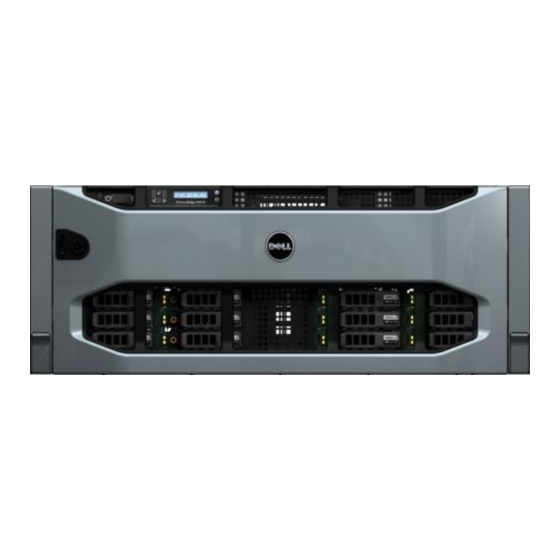
Support for persistent storage (internal USB and SD card slots and external SD card slot) Updated power supply removal process R910 Front View with Bezel Figure 1. R910 Front View without Bezel Figure 2. Dell PowerEdge R910 Technical Guide... -
Page 16: Dimensions And Weight
Dell R910 Rear View Figure 3. 4.2 Dimensions and Weight The R910 weight with maximum configuration is 47.60 kg (105 lb). Weight empty is 26.31 kg (58 lb). Dell PowerEdge R910 Technical Guide... -
Page 17: Front Panel View And Features
(Width power w/ Rack (Height) Rack supply power Latches) bezel) bezel) Latches) supply) bezel) 48.24 42.20 17.26 35.0 20.4 699.0 753.0 mm (6.8 (18.99 (16.62 R910 Dimensions Figure 4. 4.3 Front Panel View and Features Dell PowerEdge R910 Technical Guide... -
Page 18: Figure 5. Front Panel View Of R910
128x20 pixel LCD panel with controls Two navigation buttons One select button One system ID button Non-Maskable Interrupt (NMI) button (recessed) Ambient temperature sensor Two external USB 2.0 connectors Dell PowerEdge R910 Technical Guide... -
Page 19: Back Panel View And Features
DB-9 Serial Port connector (4) RJ-45 Ethernet connectors with 1 GbE IO riser, OR (2) RJ-45 Ethernet + (2) SFP+ connectors with 10Gb IO riser Rear System ID button Rear System Status/ID blue/amber LED Dell PowerEdge R910 Technical Guide... -
Page 20: Power Supply Indicators
Figure 8. Power Indicator Codes in the Hardware Owner’s Manual for information. 4.6 NIC Indicators 1 link indicator 2 activity indicator NIC Indicators Figure 9. NIC Indicator Codes in the Hardware Owner’s Manual for information. Dell PowerEdge R910 Technical Guide... -
Page 21: Internal Chassis View
Full extension of the system out of the rack to allow serviceability of key internal components Optional cable management arm (CMA) except on racks less than 1m in depth including Dell 4200 & 2400 racks Measurements and adjustment ranges for the rack: ... -
Page 22: Figure 11. R910 Fan Cage
Dell Figure 11. R910 Fan Cage Dell PowerEdge R910 Technical Guide... -
Page 23: Cabling
Dell 4.10 Cabling SERIA VIDEO CPLD2 X8 X8 X4 X8 iDRAC INT USB POWER CPLD1 BASEBOARD EXP. BACKPLANE CTRL. PANEL DVDROM Figure 12. Cabling Diagram Dell PowerEdge R910 Technical Guide... -
Page 24: Security
A lock on the bezel is used to protect unauthorized access to system hard drives and the system cover. System status (through the LCD) is viewable when the bezel is installed. Figure 14. R910 Bezel Lock Dell PowerEdge R910 Technical Guide... -
Page 25: Hard Drive
To boot from the USB memory key, configure the USB memory key with a boot image and then specify the USB memory key in the boot sequence in the System Setup program. See Figure 15 below. Dell PowerEdge R910 Technical Guide... -
Page 26: Battery
Figure 15. USB Key Location 4.13 Battery A replaceable coin cell CR2032 3V battery is mounted on the planar to provide backup power for the Real-Time Clock and CMOS RAM on the ICH10 chip. See Figure 16 below. Dell PowerEdge R910 Technical Guide... -
Page 27: Field Replaceable Units (Fru)
Figure 16. Coin Cell Battery on Motherboard 4.14 Field Replaceable Units (FRU) The planar contains a serial EEPROM to store FRU information including Dell part number, part revision level, and serial number. The backplane SEP and the power supply microcontroller are also used to store FRU data. -
Page 28: Electrical
14.318 MHz crystal. PCI Express Gen2 support Host clock support (133 MHz) Spread spectrum support 33 MHz, 48 MHz, 100 MHz clock support 14.318 MHz clock support Dell PowerEdge R910 Technical Guide... -
Page 29: Power, Thermal, Acoustic
Option to run PCIe at Gen1 speeds instead of Gen2 6.1 Power Supplies and Power Subsystem PowerEdge R910 supports two types of power supply units (PSUs): 1100W High Output PSU 750W EnergySmart PSU Figure 17. R910 Power Supply Dell PowerEdge R910 Technical Guide... -
Page 30: Table 3. Psu System Configurations
The 12V power is then distributed to the rest of the subsystems like the backplane and optical drive from the motherboard using cables. There are several voltage regulators in the system to supply different voltage levels needed by different logic devices. Dell PowerEdge R910 Technical Guide... -
Page 31: Environmental Specifications
Under extreme operating conditions the thermal algorithm can switch the DIMMs into Double Refresh mode allowing an additional 10°C of thermal headroom. In Double Refresh mode DIMMs are allowed to operate as high as 95°C. Dell PowerEdge R910 Technical Guide... -
Page 32: Acoustics
One of the sound quality metrics in the Dell specification is prominence ratio of a tone, and this is listed in the table below. -
Page 33: Table 6. Acoustics Of The Poweredge R910
(4) Prominent tone: Criteria of D.5 and D.8 of ECMA-74 9th ed. (2005) are followed to determine if discrete tones are prominent. The system is placed in a rack with its bottom at 75 cm from the floor. The acoustical transducer is at front bystander position, ref ISO7779 (1999) Section 8.6.2. Dell PowerEdge R910 Technical Guide... -
Page 34: Table 7. Configuration Corresponding To Acoustical Data Presented
Configuration Corresponding to Acoustical Data Presented Table 7. Component Description ® Highest attach-rate range bin Intel E7540 (105- Processor Memory 2 GB(1066) Power supply Redundant, 1100-W Hard Drives 146 GB SAS, 15 krpm PCI Cards PERC H800 DVD-ROM Dell PowerEdge R910 Technical Guide... -
Page 35: Processors
Simultaneous Multi-Threading (SMT) capability Support for CPU Turbo Mode (on certain SKUs) Increases CPU frequency if operating below thermal, power and current limits Streaming SIMD (Single Instruction, Multiple Data) Extensions 2, 3, and 4 Dell PowerEdge R910 Technical Guide... -
Page 36: Supported Processors
The system will not boot up if the CPUs are not installed correctly. The supported CPU configuration is either 2-processors or 4-processors. 7.5 Additional Processor Information Refer to the Hardware Owner’s Manual for additional processor information. Dell PowerEdge R910 Technical Guide... -
Page 37: Memory
DIMM farthest from the processor (DIMM 1). Population order is identified by silkscreen and a label. The order is dependent on the memory configuration used. See Figure 18 for DIMM naming and population ordering. Dell PowerEdge R910 Technical Guide... -
Page 38: Figure 18. Poweredge R910 Dimm Naming And Numbering
Dell Figure 18. PowerEdge R910 DIMM Naming and Numbering Dell PowerEdge R910 Technical Guide... -
Page 39: Slots/Risers
For Rank sparing, one rank on each lockstep Mill Brook pair will be reserved as a spare, and in the event that another rank exceeds a threshold of correctable ECC errors, the ―failing‖ rank will be copied to the spare. Once that operation is complete, the failed rank will be disabled. Dell PowerEdge R910 Technical Guide... -
Page 40: Mirroring
The R910 uses intra-socket mirroring. 8.7 RAID The PowerEdge R910 does not support memory RAID. 8.8 Supported Configurations System Memory in the Hardware Owner’s Manual for detailed information. Dell PowerEdge R910 Technical Guide... -
Page 41: Chipset
Six UHCI and two EHCI (High-Speed 2.0) USB host controllers, with up to twelve USB ports • (R910 has four external USB ports and one internal ports dedicated for IDSM and embedded storage) • Power management interface (ACPI 3.0b compliant) Dell PowerEdge R910 Technical Guide... -
Page 42: Pci Express Connectors
Only one x16 (slot 7) out of the three physical connectors is electrically x16 as well. The other two (slots 4 & 6) are electrically x8 using a x16 physical connector for double wide GPGPU adapters. Dell PowerEdge R910 Technical Guide... -
Page 43: Bios
Dell 10 BIOS 10.1 Overview The R910 BIOS is based on the Dell BIOS core, and supports the following features: Intel Xeon Processor 7500 Series Support Simultaneous Multi-Threading (SMT) support CPU Turbo Mode support PCI 2.3 compliant ... -
Page 44: Embedded Nics/Lan On Motherboard (Lom)
Wake-On-LAN (WOL) PXE 2.0 remote boot iSCSI boot IPv4 and IPv6 support Bare metal deployment support NOTE: Four functional PSUs (2+2 config) are required in order to use the 10Gb I/O riser. Dell PowerEdge R910 Technical Guide... -
Page 45: O Slots
System supports 25 W maximum power capability for each expansion slot R910 does not support hot-swapping of PCIe cards R910 does not support full length PCIe cards Figure 19. PCIe I/O slots Dell PowerEdge R910 Technical Guide... -
Page 46: Quantities And Priorities
x16 card must be able to support a maximum operating temperature of 55°C as defined in the Dell PCI Environmental Spec and the PCI Express Card Electromechanical Spec (See Product Safety, EMC and Environmental Datasheets on Dell.com). The R910 provides a minimum transverse air velocity of “x”... -
Page 47: Storage
Only 2.5” HDD are supported in this configuration One Mini-SAS cable is used to connect channel “A” of the integrated PERC H200 or H700 storage controller card to the four-drive backplane. Mixing SATA and SAS is NOT supported. Dell PowerEdge R910 Technical Guide... -
Page 48: X16 Backplane
A SAS expander is used to map 16 HDD to the PERC H700 (2 x4 SAS) controller Mixing SATA and SAS is NOT supported. Mixing SAS and SSD is supported. 6 Gb SAS EXPANDER Figure 21. 2.5” x16 Backplane Dell PowerEdge R910 Technical Guide... -
Page 49: Flash Bios Memory
SEP device on the backplane. Both LEDs are used to indicate certain conditions under direction of a storage controller. R910 Supported HDDs Table 10. SAS HDD (2.5‖) 146GB, 300GB SATA HDD (2.5‖) 160GB SATA SSD (2.5‖) 50GB, 100GB Dell PowerEdge R910 Technical Guide... -
Page 50: Raid Configurations
4 (2+2) 4 (2+2) RAID 1 (PERC H700, PERC H200) MSSR1R5 Integrated SAS HDD/ SSD RAID 5 (2+3) 1/RAID 5 (PERC H700) (2+14) MSSR1R6 Integrated SAS HDD/ SSD RAID 5 (2+4) 1/RAID 6 (PERC H700) (2+14) Dell PowerEdge R910 Technical Guide... - Page 51 The x16 Backplane is supported only by PERC H700. The x4 Backplane is supported by both PERC H200 & PERC H700. SATA HDDs will be supported only on x4 Backplane. Max of only 1 SATA HDDs allowed and is only in C1 config. Dell PowerEdge R910 Technical Guide...
-
Page 52: Storage Controllers
LSI 2108 (Liberator) ROC • 6Gb/s SAS • x8 PCIe Gen2 • 800Mz Core PPC • DDRII - 800MHz – mini-DIMM • 512MB Dual Mini-SAS Connectors • Supports connection to PowerVault MD1220 and PowerVault MD1200 6Gb enclosures only Dell PowerEdge R910 Technical Guide... -
Page 53: Storage Card Support Matrix
Internal SATA On Planar Yes - Optical 1 port for x1 int chipset Optical (No HDD) External SCSI Yes - Max 2 LSI 2032 Tape or External SCSI PCIe slot Adapter legacy SCSI (ext) storage Dell PowerEdge R910 Technical Guide... -
Page 54: Led Indicators
ICH10. IDE (PATA) optical drives are not supported. The following internal optical drives are available on R910: DVD-ROM and DVD+RW. If the optical drive is not ordered with the system, a blank is installed in its place. Dell PowerEdge R910 Technical Guide... -
Page 55: Video
Dell 14 Video The R910 Integrated Dell Remote Access Controller 6 (iDRAC6) incorporates an integrated video subsystem, connected to the 32-bit PCI interface of the ICH10. This logic is based on the Matrox G200. The device only supports 2D graphics. -
Page 56: Audio
Dell 15 Audio R910 does not support speakers or audio output. Dell PowerEdge R910 Technical Guide... -
Page 57: Rack Information
Threaded hole racks require Dell’s fixed shelf or adapter brackets available from RackSolutions. The CMA is not supported on racks that are less than 1m in depth including Dell’s 4200 & 2400 racks. 16.2 Rails The ReadyRails sliding rails for the R910 support tool-less mounting in 19‖-wide, EIA-310-E compliant square hole and unthreaded round hole racks and are available with or without the optional cable management arm (CMA). -
Page 58: Cable Management Arm (Cma)
The R910 ReadyRails sliding rails are a ―drop-in‖ design, meaning that the system is installed vertically into the rails by inserting the shoulder nuts on the sides of the system into the J-slots in the inner rail members with the rails in the fully extended position. Dell PowerEdge R910 Technical Guide... -
Page 59: Figure 24. R910 Mounted In The B2 Sliding Rails
Figure 25. R910 CMA Mounted on the Side Opposite the Power Supplies (Recommended) Dell PowerEdge R910 Technical Guide... -
Page 60: Operating Systems
Dell 17 Operating Systems For the most up-to-date information, see the Operating System Support Matrix for Dell PowerEdge Systems on Dell.com. Dell PowerEdge R910 Technical Guide... -
Page 61: Virtualization
Dell 18 Virtualization The following virtualization software is supported: Microsoft Windows Server 2008 Hyper-V VMware ESXi Version 4.0 update1 ® Citrix XenServer™ 5.6 Dell PowerEdge R910 Technical Guide... -
Page 62: Systems Management
19 Systems Management 19.1 Overview/Description Dell aims on delivering open, flexible, and integrated solutions that help you reduce the complexity of managing disparate IT assets by building comprehensive IT management solutions. Combining Dell PowerEdge Servers with a wide selection of Dell-developed management solutions gives you choice and flexibility, so you can simplify and save in environments of any size. -
Page 63: Embedded Server Management
For servers without iDRAC Express, this utility has limited functionality and offers OS install and diagnostics capabilities only. To access the Unified Server Configurator, press the <F10> key within 10 seconds of the Dell logo’s appearance during the system boot process. Current functionality enabled by the Unified Server... -
Page 64: Optional Idrac Express
Additionally, the iDRAC6 Enterprise can be upgraded by adding the vFlash Media card. This is a 1 GB Dell branded SD card that enables a persistent 256 MB virtual flash partition. In the future, vFlash will be expanded to include additional features. - Page 65 sharing Virtual flash Monitoring Sensor Monitoring and Alerting Real-time Power Monitoring Real-time Power Graphing Historical Power Counters Logging Features Dell PowerEdge R910 Technical Guide...
- Page 66 Dell Feature iDRAC 6 Express iDRAC6 Enterprise vFlash Media System Event Log RAC Log Trace Log Dell PowerEdge R910 Technical Guide...
-
Page 67: Peripherals
Attachment to EMC NS500G (S&P) PV DAS MD1000 JBOD MD3000 RBOD MD1120 2.5 SAS/SATA JBOD MD1100 3.5 SAS/SATA JBOD PV SAN MD3000i iSCSI RAID array EqualLogic™ PS5000 family PS5500 family IDM support SAS xBOD SW OpenManage Storage Manager Dell PowerEdge R910 Technical Guide... -
Page 68: Table 19. Standards Compliance
SATA II, Extensions to SATA 1.0a, Rev. 1.2 SMBIOS http://www.dmtf.org/standards/smbios/ System Management BIOS Reference Specification, v2.6 https://www.trustedcomputinggroup.org/downloads/specific ations/tpm/tpm Trusted Platform Module Specification, v1.2 UEFI http://www.uefi.org/specs/ Unified Extensible Firmware Interface Specification, v2.1 http://www.usb.org/developers/docs/ Universal Serial Bus Specification, Rev. 2.0 Dell PowerEdge R910 Technical Guide... - Page 69 Dell Standard URL for Information and Specifications Windows Logo http://www.microsoft.com/whdc/winlogo/hwrequirements. Windows Logo Program mspx System and Device Requirements, v3.10 Dell PowerEdge R910 Technical Guide...
-
Page 70: R910 Volatility
Purpose? [e.g., boot code] iDRAC boot loader and configuration (i.e. MAC address), Lifecycle log. How is data input to this memory? Data pre-programmed or update using Dell utility which is a DOS or Windows or Linux based Dell PowerEdge R910 Technical Guide... - Page 71 How is data input to this memory? For SEL, BMC writes to it. For FRU, data is pre-programmed or input using Dell utility at ICT/Functional Tester during board assembly. How is this memory write protected? Software write protected...
- Page 72 FRU information for boards such as board name, PPID, manufacturing date etc. How is data input to this memory? Data pre-programmed or using Dell utility at ICT/Functional Tester during board assembly. How is this memory write protected? Not write protected...
- Page 73 5709C controllers where as on 10Gb I/O riser, one is for 5709C and the other one is for 57711 network controller. Broadcom 8727 PHY (Physical Layer) EEPROM (applicable to only 10Gb I/O riser) Size: 32KB Dell PowerEdge R910 Technical Guide...
- Page 74 Data is preprogrammed at board build How is this memory write protected? Software write protected Remarks 10Gb I/O riser is optional Dell PERC H700i storage controller CPLD/Flash/NVSRAM etc. (if applicable) Size: FRU: 256 Bytes Boot ROM: 8 KB Flash: 8 MB...
- Page 75 FRU is not write protected but other components detailed above in the Size row are software write protected. Remarks PERC H700i controller is optional Dell PERC H200i storage controller Flash/NVSRAM/FRU (if applicable) Size: FRU: 256 Bytes Boot ROM: 8 KB Flash: 8 MB NVSRAM: 128 KB Type [e.g., Flash PROM, EEPROM]:...
- Page 76 Purpose? [e.g., boot code] Store SAS expander firmware and configuration data How is data input to this memory? Data pre-programmed or update using Dell utility which is a DOS-based executable containing the firmware file and loader. How is this memory write protected?
- Page 77 How is this memory write protected? Software write protected Remarks IDSM is an option Dell Internal Dual SD Module (IDSM) write journal flash (if present) Size: 8 MB Type [e.g., Flash PROM, EEPROM]: EEPROM Can user programs or operating system write...
- Page 78 (i.e., ISO images, files) or local server read/write capability to use like a hard disk. How is this memory write protected? Media write protection or Software write protected Remarks iDRAC Enterprise and vFlash are optional Dell PowerEdge R910 Technical Guide...