Table of Contents
Advertisement
Quick Links
MULTI
MULTI SCREEN
LOCK
SCRE EN
CAME RA/PR E SET POSIT
SELEC T
ALAR M
1
2
3
POWE R
RESE T
SPOT
SEQUEN CET
5
6
7
ON
OFF
9
10
VCR
11
CAM
13
14
15
Before attempting to connect or operate this product,
please read these instructions carefully and save this manual for future use.
Operating Instructions
Model No.
ION
4
PUS H OPE N
8
12
16
Video Multiplexer
WJ-FS616C
Advertisement
Table of Contents

Related Manuals for Panasonic WJ-FS616C


Summary of Contents for Panasonic WJ-FS616C
-
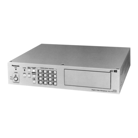
Page 1: Operating Instructions
Video Multiplexer Operating Instructions WJ-FS616C Model No. MULTI MULTI SCREEN LOCK SCRE EN CAME RA/PR E SET POSIT SELEC T ALAR M PUS H OPE N POWE R RESE T SPOT SEQUEN CET Before attempting to connect or operate this product, please read these instructions carefully and save this manual for future use. - Page 2 Caution: Before attempting to connect or operate this product, please read the label on the bottom. For U.S.A NOTE: This equipment has been tested and found to com- ply with the limits for a Class A digital device, pursuant to Part 15 of the FCC Rules.
-
Page 3: Important Safety Instructions
IMPORTANT SAFETY INSTRUCTIONS 1) Read these instructions. 2) Keep these instructions. 3) Heed all warnings. 4) Follow all instructions. 5) Do not use this apparatus near water. 6) Clean only with dry cloth. 7) Do not block any ventilation openings. Install in accordance with the manufacturer's instructions. 8) Do not use near any heat sources such as radiators, heat registers, stoves, or other apparatus (including amplifiers) that produce heat. -
Page 4: Table Of Contents
CONTENTS IMPORTANT SAFETY INSTRUCTIONS ......3 Sequence Timing (Multiscreen Monitor) ....40 PREFACE ................5 Sequence Timing (Spot Monitor) ....... 40 FEATURES ................ 5 Lock Mode ..............41 PRECAUTIONS ..............6 Cable Compensation/VD2/Data ......... 41 MAJOR OPERATING CONTROLS AND Alarm Terminal Setup ..........41 THEIR FUNCTIONS ............ -
Page 5: Preface
Panasonic Time Lapse VCR. The pattern of a 4, 7, 9, 10, 13, or 16 multiscreen sequence consisting of up to 5 steps can be pro- •... -
Page 6: Precautions
PRECAUTIONS • Refer all work related to the installation of this • Fully charge up the backup battery. product to qualified service personnel or system Keep the appliance turned on for at least 48 hours to installers. recharge the backup battery. This procedure is neces- sary when using the appliance for the first time or after •... -
Page 7: Major Operating Controls And Their Functions
MAJOR OPERATING CONTROLS AND THEIR FUNCTIONS Front View e r t y u i MULTI MULTISCREEN CAMERA/PRESET POSITION PUSH OPEN ALARM SCREEN SELECT LOCK POWER RESET SPOT SEQUENCE Digital Video Multiplexer WJ-FS CURSOR / CAMERA CONTOROL FUNCTION SET UP/ESC LOCK I R I S CLOSE OPEN... - Page 8 t Spot Monitor Button (SPOT) !0 VCR/Camera Selection Button (VCR/CAM) This button is used to operate the spot monitor connect- This button is used to select the camera image or VCR ed to the SPOT OUT connector on the rear of the video playback image to be displayed on the multiscreen multiplexer.
- Page 9 @6 Direction Buttons (UP/DOWN/LEFT/RIGHT) #2 L ock Switch (LOCK OFF/ON) These buttons are used to manually operate the Pan/Tilt This switch can be used to lock out operation of the Head, move the cursor position in the setup menu of video multiplexer panel controls.
-
Page 10: Rear View
Rear View LINE CAMERA SELECT RS485 TERM. GENLOCK SW IN REC OUT PLAY IN MULTISCREEN OUT VCR CONTROL SPOT IN (VS) RS–232C VIDEO S–VIDEO VIDEO S–VIDEO VIDEO S–VIDEO ALARM/REMOTE REMOTE CAMERA DATA TERM. CAMERA SIGNAL $1 Camera Output Connectors (CAMERA OUT) The supplied video can be displayed on the spot monitor screen with the specified conditions. - Page 11 %6 Signal Ground Terminal (SIGNAL GND) %7 Data Termination Switch (TERM., OFF/ON) This switch is used to enable termination of the video multiplexer’s data port. %8 Data Port (DATA, OUT/IN) These ports are used to exchange control data with the specified system controller or a PC in a system.
-
Page 12: Installation
INSTALLATION The installations described below should be made by 4. Remove the one screw shown below. Then turn over the printed circuit board with the front side up. the qualified service personnel or system installers. Installing the WV-PB6164 Data Multiplex Boards When controlling the camera with the multiplexed control data by connecting a coaxial cable, the WV-PB6164 Data Multiplex Board must be installed in the video multiplexer. -
Page 13: Tally Output Setting
6. Set the jumper connector, that is located at the top left Tally Output Setting of the board, to the position shown below where the Allows you to use the Alarm Input terminal on the board is installed. ALARM/REMOTE port as Tally Output terminal by Jumper Connector changing two internal connections. -
Page 14: Dip Switch Setting
DIP Switch Setting Alarm Output Setting The following settings let you set the polarities of alarm out- put, alarm reset output, and alarm & SW output on the ALARM/REMOTE port. 1. Disassemble the video multiplexer as described for installing the Data Multiplex Boards on page 12. 0/5V SW3 : Alarm Output 2. -
Page 15: Mounting Into The Rack
Mounting into the Rack Cautions: • The cooling fan inside the video multiplexer is sub- The video multiplexer can be mounted into the rack as ject to wear and needs to be replaced periodically. described below. • Do not block the ventilation opening or slots on the cover to prevent the appliance from overheating. -
Page 16: Connections
CONNECTIONS Shown below is an example of a basic system connection. Alarm Video Alarm Sensor Data RS-485 Video Multiplexer WJ-FS616C MULTI MULTISCREEN CAMERA/PRESET POSITION ALARM SCREEN SELECT PUSH OPEN LOCK POWER RESET SPOT SEQUENCE Digital Video Multiplexer WJ-FS RS-232C/Wired Time Lapse VCR ALARM BUSY Spot Monitor... -
Page 17: Connection With The Camera Sites
Connection with the Camera Sites For cameras equipped with RS-485 communication facility, connect the RS-485 cable as follows. Connect cameras (or camera site equipment) data mul- Note: If you use cables assembled from locally pro- tiplexed type to the CAMERA IN connectors 1 through 4 cured materials, it is important that only high quality, on the rear of the video multiplexer. -
Page 18: Connections For Rs-485 Type Camera
Connections for RS-485 type camera (2) Connect cameras in a Daisy Chain 1. Draw up a plan for connection between the cameras There are two options to connect the camera with the and the input channels of the video multiplexer, and the multiplexer, depending on the distance between them. -
Page 19: Connection With The Monitors
Connection with the Monitors Connect the Monitors to the SPOT OUT connector and DATA port MULTISCREEN OUT connector on the rear of the video • In page 2 of 2 of the SYSTEM SETUP menu, set the multiplexer with the coaxial cable. DATA MODE to PC and press the [SET UP/ESC] button to activate the DATA port on the rear panel. -
Page 20: Connection With Alarm Sensors
Connection with Alarm Sensors Connect the sensor switches to the ALARM/REMOTE port on the rear of the video multiplexer as shown in the example below. ALARM/REMOTE Pin No. Designation Pin No. Designation Function Still Picture Electronic Zoom VCR/Camera Select Sequence Multiscreen Select Spot Multiscreen... - Page 21 MONITORS AND DISPLAYS Spot and Multiscreen Monitor The WJ-FS616C video multiplexer can be connected to two monitors. The monitor displays the video signal according to the connection made, as shown below. Spot Monitor: The monitor that is connected to the SPOT OUT connector on the rear of the video multi- plexer.
-
Page 22: Connection With The Time Lapse Vcr
Connection with the Time Lapse VCR Connect the time lapse VCR as shown in the example below. Video Multiplexer WJ-FS616C VCR CONTROL CAMERA REC OUT PLAY IN R2–232C SW IN VIDEO S–VIDEO VIDEO S–VIDEO See Notes REMOTE ALARM/REMOTE Time Lapse VCR VIDEO IN VIDEO OUT S-VIDEO... -
Page 23: Setup Procedures
SETUP PROCEDURES... -
Page 24: Setup Menu
SETUP MENU The setup menu provides a way for controlling functions 3. Press the [SET UP/ESC] button to execute the currently that are not available by a direct operation. highlighted setting and return to the previous menu in the SETUP MENU. Displaying the SETUP MENU 4. -
Page 25: Programming Setup Menu
Programming Setup Menu As shown below, the SETUP MENU has nine main submenus: Alarm Setup, Multiscreen Output Setup, Spot Output Setup, Record Output Setup, Multiscreen 2 Output Setup, System Setup, Camera Download, Camera Upload and All Reset. Six of these submenus; Alarm Setup, Multiscreen Output Setup, Spot Output Setup, Record Output Setup, Multiscreen 2 Output Setup and System Setup are further divided into additional submenus. -
Page 26: Alarm Setup
ALARM SETUP The procedure described below let you set the modes 4. To clear all alarm records, press the A or B button to when an alarm is received. select CLEAR where the cursor is positioned, then press the [HOME/SET] button. Move the cursor to ALARM SETUP in the SETUP MENU by pressing the C or D button and then press the 5. -
Page 27: Camera Site Alarm
Camera Site Alarm Alarm Display on the Monitors This item lets you enable or disable the camera site alarm This item lets you enable or disable alarm display on the function. spot and multiscreen monitors. 1. Move the cursor to the CAM SITE ALM parameter by 1. -
Page 28: Alarm Mode On The Multiscreen Monitor
Alarm Mode on the Multiscreen Alarm Mode on the Spot Monitor Monitor This item lets you select the mode for displaying an alarm on the spot monitor. This item lets you select the mode for displaying an alarm on the multiscreen monitor. 1. -
Page 29: Multiscreen Output Setup
MULTISCREEN OUTPUT SETUP The procedure described below let you determine the dis- Clock Display play mode of the multiscreen monitor. This item lets you enable or disable the clock display on the multiscreen monitor. WJ-FS616C SETUP MENU ALARM SETUP * 1. -
Page 30: Camera Display Position Setting
Camera Display Position Setting Secret View This item lets you assign the position where the camera When the camera image is displayed in the spot mode on image will be displayed on the multiscreen monitor. the spot monitor, the multiscreen monitor is enabled to skip the step in sequence or display a blackout in multiscreen 1. -
Page 31: Spot Output Setup
SPOT OUTPUT SETUP The procedure described below let you determine the dis- Camera Title Display play mode of the spot monitor. This item lets you enable or disable display of the camera title on the spot monitor. WJ-FS616C SETUP MENU ALARM SETUP * 1. -
Page 32: Record Or Multiscreen 2 Output Setup
RECORD OR MULTISCREEN 2 OUTPUT SETUP The procedure described below let you determine the Record Output Setup mode for the REC OUT connector on the rear of the video Select REC OUTPUT in the menu and then press the multiplexer. [HOME/SET] button. - Page 33 Dynamic Recording Recording Mode Setup This item lets you select the cameras for dynamic recording This item lets you select a recording mode on the time mode in non-alarm condition. lapse VCR. If five or more cameras are connected to the video multi- plexer, the channels selected for dynamic recording are 1.
-
Page 34: Multiscreen 2 Output Setup
3. Select the desired switching timing indicated as the Multiscreen 2 Output Setup field interval (4 to 999) by pressing the A or B button. These items let you select the display mode when connect- Notes: ing the Record Output (REC OUT) to the monitor for multi- •... - Page 35 Camera Display Position This item lets you select the position where the camera images will be displayed on the multiscreen 2 monitor. 1. Move the cursor to DISPLAY POSITION, then press the [HOME/SET] button. The table shown in the figure appears on the monitor. 2.
-
Page 36: System Setup
SYSTEM SETUP The procedure described below let you determine the sys- Clock Setup tem designation and display the system status. This item lets you set the current time and date. WJ-FS616C SETUP MENU 1. Move the cursor to CLOCK SETUP in the SYSTEM ALARM SETUP * SETUP menu and then press the [HOME/SET] button. -
Page 37: Camera Title Setup
Camera Title Setup 8. Press the [FUNCTION] button to display the next page, then press this button again to return to the previous This item lets you edit the camera title to be displayed on page. the monitor screen. Up to 8 alphanumeric characters can be displayed on the 9. - Page 38 2. Select SEQ1 and then press the [HOME/SET] button. 2. Select the desired preset position number for the cam- era in the PRE column by pressing the - or + button. The SEQ1 SETUP menu shown in the figure appears on the monitor screen.
- Page 39 4. After finishing the settings, press the [SET UP/ESC] but- Camera/Playback ton to execute the settings and return to the previous SYSTEM SETUP menu. This item lets you select the camera or playback image to be displayed at each step. Multi Sequence (SEQ2, SEQ3) 1.
-
Page 40: Sequence Timing (Multiscreen Monitor)
Preset Position Notes: • If EXT is selected, time adjustment input from a 1. Move the cursor to the PRE column you want to edit for Time Lapse VCR is disabled. the area number by pressing the C, D, A or B button. •... -
Page 41: Cable Compensation/Vd2/Data
Cable Compensation/VD2/Data 5. Select either ON or OFF in the VD2 column by pressing the - or + button. This item lets you select the optimum setting for the cable- loss compensator and whether to supply the VD2 (sync) Note: Select ON for a camera with VD2 capability, oth- signal or control data to the camera. -
Page 42: Playback Mode
4. Select the preset position number to be assigned in the RS-232C Mode PRE column by pressing the - or + button. This item lets you select the RS-232C port for control of the VCR, or for external control of the system from a PC. 5. -
Page 43: Vcr Input Select
5. Select the desired waiting time for WAIT TIME by press- Daisy Mode ing the - or + button. This item lets you select whether to have the video signal This item lets you set the waiting time to retry if there is connected to SPOT IN looped through to the SPOT OUT no response from the connected device. -
Page 44: Password
Password This item lets you select whether to permit free or limited access to the setup menus. When PASSWORD is set to ON, the operator must enter the password to access the setup menus. 1. Move the cursor to the PASSWORD parameter in the SYSTEM SETUP menu. -
Page 45: Other Setup Menus
OTHER SETUP MENUS Camera Download Camera Upload This item lets you save the camera setup data into the This item lets you upload camera setup data from the video memory of the video multiplexer. multiplexer’s memory to a camera. If the setup contents of the camera should be lost due to malfunctioning or replacement of a camera, you can simply 1. -
Page 46: All Reset
All Reset This item lets you restore the factory settings without having to go through each individual menu. 1. Move the cursor to ALL RESET SELECT in the SETUP MENU, then press the [HOME/SET] button. The ALL RESET SELECT menu shown in the figure appears on the monitor screen. -
Page 47: Operating Procedures
OPERATING PROCEDURES... -
Page 48: Controlling The Video Input And Monitors
CONTROLLING THE VIDEO INPUT AND MONITORS Before starting the following procedures, all system Single Sequence (Live) components should be turned on. A series of camera images can be displayed in succession Then set the LOCK switch to the OFF position. on the monitor screen for the specified duration. -
Page 49: Controlling The Multiscreen Monitor
Controlling the Multiscreen The indicator in the selected button lights and the cam- era image corresponding to the button appears on the Monitor monitor screen. The operations described below are available on the multi- screen monitor. Note: We recommend using the spot monitor in single spot for preventing image disturbance when displaying non- interlace images. - Page 50 3. To cancel this mode, press the [STILL] button to return Multiscreen Spot (Live) to the image previously shown. The monitor can display the camera images on a 4, 7, 9, The indicator in the button goes off. 10, 13 and 16 multiscreen shown below. 1.
-
Page 51: Controlling The Playback Images
2. Press the [STILL] button. The indicator in the button SEQUENCE lights. 3. Select an image to be frozen on the monitor by press- ing a [1 – 16] button. The indicator in the selected button start blink and the camera image corresponding to the button is displayed 9 10 11 12 in freeze on the monitor screen. - Page 52 2. Select the VCR playback mode (indicator on) by press- Single Spot (Playback) ing the [VCR/CAM] button. 1. Select an image to be displayed on the monitor by pressing a [1 – 16] button. The indicator in the selected button lights and the play- back image corresponding to the button appears on the monitor screen.
- Page 53 Zooming Single Spot (Playback) Freezing Multiscreen Spot (Playback) While the image on the monitor screen is displayed in sin- The monitor can display the freeze playback images on a 4, gle spot mode, the image can be zoomed followed the pro- 9 and 16 multiscreen shown below.
-
Page 54: Displaying The Camera And Playback Images
3. To return to single spot monitoring, select an image to 3. Press the [FUNCTION] button. The indicator in the but- be displayed by pressing a [1 – 16] button. ton starts to blink. Or to return to screen segments display, press the [MULTISCREEN SELECT] button. - Page 55 Freezing Multiscreen Spot (Live Images with a Playback Image) The monitor can display the freeze camera images on a 4-, 7-, 10- or 13-segment multiscreen while cameras with play- back images are displayed. 1. Repeat steps 1 to 4 referring the procedure in the Multiscreen Spot.
-
Page 56: Camera Control Function
CAMERA CONTROL FUNCTION The camera control is only available while the camera Pressing both of these buttons simultaneously will auto- image is displayed in single spot on the selected monitor matically set the lens focus, if the specified camera with screen and the LOCK switch is in OFF position. - Page 57 Pan/Tilt Control (Preset Operation) 3. To cancel the auto panning function, press one of the Direction buttons. The following function requires the use of cameras equipped with the specific feature. Note: When using the combination cameras with auto panning feature, make sure that the LOCAL/ Note: Select only preset position numbers 1 to 16.
- Page 58 7. Press the [SET UP/ESC] button, while holding the [FUNCTION] button, to exit from the setup mode or menu. FUNCTION SET UP/ESC Note: Refer to the operating instructions of the selected camera for further details. Caution: Camera addresses are important for RS-485 type cameras.
-
Page 59: Alarm Control Function
ALARM CONTROL FUNCTION The alarm function activates the warning alarm status, when Alarm Operation an externally connected alarm sensor is turned on. When an alarm signal is received, the multiplexer, the Described below is an example of an alarm status activa- Record Output, Spot Output and Multiscreen Output of the tion. - Page 60 Multiscreen Output • Alarm Indication Mode • The camera images selected before the alarm was The alarmed input image and alarm display are displayed activated remain on the monitor screen. on the multiscreen monitor as shown below. • If the alarmed channels are displayed, the camera Described below are several examples;...
-
Page 61: Alarm Reset
Alarm Reset Example of Using Multiscreen 2 Monitor Manual Reset The figure below shows an example of how alarm is dis- played when a Multiscreen 2 Monitor is connected to the When an alarm is activated, the ALARM indicator blinks. REC OUT connector. -
Page 62: Alarm Suspension
Alarm Suspension This function disables activation of the alarm link and instead enables storing of any alarm activated in the alarm log. It is used to suspend the alarm link during camera setup. To suspend the alarm: 1. Press the [RESET] and [SPOT] buttons at the time for 2 seconds or more to suspend the alarm. -
Page 63: Other Function
OTHER FUNCTION Recording on the Time Lapse VCR The following selections are made in the WJ-FS616C SETUP MENU described previously. Refer to the Recording Mode Setup on page 33 for further details. 1. Check the selected recording mode (MODE 0 - MODE MODE 0: Normal Mode (Real Time) MODE 1 - 9: Time Lapse Mode (Linear Mode) If MODE 9 is selected, check the image (spot or... - Page 64 OPERATING PROCEDURES (with WV-CU550C)
-
Page 65: Operating Procedures (With Wv-Cu550C)
SYSTEM CONTROLLER WV-CU550C The WJ-FS616C video multiplexer can be controlled from the WV-CU550C system controller. The following procedures apply when the WV-CU550C system controller is connected to the system. Major Operating Controls and Their Functions Note: When using this controller in combination with the WJ-FS616C, cover the panel of the controller with the panel templates provided. -
Page 66: System Controller Wv-Cu550C
q Alarm Indicator (ALARM) y Joystick Controller This indicator (Red) lights to indicate that an alarm con- The joystick is used to manually operate the Pan/Tilt dition exists. Head, move the cursor position in the setup menu of It goes off when the alarm is reset automatically. the video multiplexer, or to select an area for Electronic To turn the ALARM indicator off of the multiplexer, press Zooming. - Page 67 !6 Function button (FUNCTION) @3 Data ports (DATA, IN/OUT) This button is used to display the camera images with a Exchanges control data with the video multiplexer in a VCR playback image on the multiscreen monitor. system. While displaying the setup menu on the monitor, press- @4 Termination switch (TERM., ON/OFF) ing this button will select the next page of the setup menu.
-
Page 68: Installations
Installations • Setting the Termination and Controller Unit Number The Termination switch and the Controller Unit Number The installations described below should be made by switch are located on the rear of the system controller. qualified service personnel or system installers. When combined with the WJ-FS616C video multiplexer, always keep these switches in the positions shown Modifying the Front Panel... -
Page 69: Setup Menu Operations (With Wv-Cu550C)
SETUP MENU OPERATIONS (WITH WV-CU550C) During setup of the WJ-FS616C with the WV-CU550C system controller, the following buttons and keys of the system controller correspond with those of the WJ-FS616C as shown below. WJ-FS616C WV-CU550C Function SET UP SET UP/ESC Display the SETUP MENU or escape from the menu. -
Page 70: Controlling The Video Input And Monitors
FUNCTION OPERATIONS (WITH WV-CU550C) When operating the video multiplexer with the WV-CU550C Controlling the Video Input and system controller, the following buttons and keys of the sys- Monitors tem controller correspond with those of the video multiplex- To select a monitor and camera, follow the procedure shown below. -
Page 71: Function Operations (With Wv-Cu550C)
Camera Control Function 3. Press the [ZOOM] button to adjust the lens zoom to achieve the desired image while observing the active monitor. The camera control is only available while the camera Press this button to the [TELE] position to optically bring image is displayed in single spot on the selected monitor an object closer. -
Page 72: Camera Selection
3. Press the [CAM(SET)] key to move the pan/tilt head to SET UP CAMERA CAMERA SET ON SET OFF the preset position on the active monitor. T/L MODE PLAY Pan/Tilt Control (Home Position) U01 C01 CamSet Up The following function requires the use of cameras RES A.RES equipped with the specific feature. -
Page 73: Alarm Control Function
Auxiliary Control Alarm Control Function The following function is available only with a system that includes WV-RC100 or WV-RC150 Receivers. Alarm Suspension 1. Select the desired monitor and camera referring to the This function disables activation of the alarm link and Camera Selection procedure described above. -
Page 74: System Expansion
SYSTEM EXPANSION The system shown below is an example of the expansion capabilities of the WJ-FS616C video multiplexer. Up to four video multiplexers can be connected to expand the camera inputs. Main Site (Unit 1) Local Site (Unit 2) Camera 1 -16 Camera 1 -16 Alarm Alarm... -
Page 75: Connections
Connections For example, press the keys shown below. In this type of installation, only one video multiplexer is con- nected directly to the system controller by a control cable. The rest of the video multiplexers are connected to the sys- UNIT/ESC tem controller in a daisy-chain type connection. - Page 76 Application 2 The camera images in the Local Site (Unit 2) can be dis- played on the multiscreen monitor in the Main Site (Unit 1) by connecting a coaxial cable shown below. Video Multiplexer REC OUT VIDEO S–VIDEO Local Site Coaxial Cable RG-59/U less than 250m (800 ft) Video Multiplexer...
-
Page 77: Appendix
APPENDIX This Appendix details the elements for communication between the Video Multiplexer and the personal computer. For BAUD RATE, DATA BIT, STOP BIT and PARITY settings, see page 42 COM PORT SETUP menu. Communication Protocol 1. Transmission Command The PC sends messages to operate the Multiplexer in the format shown below. Also refer to the command table shown later. -
Page 78: Command Table
Command Table (1) Operation Control Transmission Response Item Parameter (ASCII) Command (ASCII) Command (ASCII) Spot Monitor Monitor Select OMS : m Multiscreen Monitor Multiscreen 2 Monitor Camera Mode VCR/Camera Select OVC : m VCR Mode Still OFF Still ON Still ON/OFF OST : m : nn nn=00 All video channels specify nn=01 - 16 Camera Number... - Page 79 (3) Cursor Control Transmission Response Item Parameter (ASCII) Command (ASCII) Command (ASCII) Cursor Movement DCR : mm mm=UU Move Upward Select Parameter mm=DD Move Downward mm=RR Move to Right mm=LL Move to Left mm=BB Move to lower layer mm=ES Move to upper layer Item decision (partial) mm=IC Select parameter (+)
- Page 80 Examples of response Response Command (ASCII) Main Unit Information @mPLSNcc Single Spot (Camera) @mPLSZcc Single Spot + Electronic Zoom (Camera) @mPLSScc Single Spot + Still (Camera) @mPLSXcc Single Spot + Zoom + Still (Camera) @mPLSMLa Multi Spot (+ Still) (Camera) @mPLQNcc Spot Sequence (Camera) @mPLQMLa...
-
Page 81: Standard Accessories
SPECIFICATIONS Power Source: 120 V AC 60 Hz Power Consumption: 50 W Camera Input (1-16): 1.0 V[p-p] /75 composite video signal 0.5 V[p-p] /75 data signal and 2.5 V[p-p] /75 vertical timing pulse multiplexed. Camera Output (1-16): 1.0 V[p-p] /75 composite video signal Spot Output: 1.0 V[p-p] /75... - Page 82 Panasonic Canada Inc. 5770 Ambler Drive, Mississauga, A Division of Matsushita Electric Corporation of America Ontario, L4W 2T3 Canada (905)624-5010 Executive Office: One Panasonic Way 3E-7, Secaucus, New Jersey 07094 Panasonic Sales Company Regional Offices: Division of Matsushita Electricof Puerto Rico Inc.