Table of Contents
Advertisement
Advertisement
Table of Contents

Related Manuals for Asus M4A78-VM IN SI


Summary of Contents for Asus M4A78-VM IN SI
- Page 1 M4A78-VM IN/SI...
- Page 2 Product warranty or service will not be extended if: (1) the product is repaired, modified or altered, unless such repair, modification of alteration is authorized in writing by ASUS; or (2) the serial number of the product is defaced or missing.
-
Page 3: Table Of Contents
Chapter 2: BIOS information Managing and updating your BIOS ..........2-1 2.1.1 ASUS Update utility ............2-1 ASUS EZ Flash 2 utility ........... 2-2 2.1.2 2.1.3 ASUS CrashFree BIOS 3 utility ........2-2 BIOS setup program ..............2-3 Main menu ..................2-4 2.3.1... - Page 4 2.5.5 HW Monitor Configuration ..........2-11 Boot menu .................. 2-12 2.6.1 Boot Device Priority ............2-12 2.6.2 Boot Settings Configuration .......... 2-12 2.6.3 Security ................. 2-13 Tools menu ................. 2-14 2.7.1 ASUS EZ Flash 2 ............2-14 Exit menu ..................2-14...
-
Page 5: Notices
Complying with the REACH (Registration, Evaluation, Authorisation, and Restriction of Chemicals) regulatory framework, we published the chemical substances in our products at ASUS REACH website at http://green.asus.com/english/REACH.htm. DO NOT throw the motherboard in municipal waste. This product has been designed to enable proper reuse of parts and recycling. -
Page 6: Safety Information
Safety information Electrical safety • To prevent electric shock hazard, disconnect the power cable from the electric outlet before relocating the system. • When adding or removing devices to or from the system, ensure that the power cables for the devices are unplugged before the signal cables are connected. If possible, disconnect all power cables from the existing system before you add a device. -
Page 7: Conventions Used In This Guide
Refer to the following sources for additional information and for product and software updates. ASUS websites The ASUS website provides updated information on ASUS hardware and software products. Refer to the ASUS contact information. Optional documentation Your product package may include optional documentation, such as warranty flyers, that may have been added by your dealer. -
Page 8: M4A78-Vm In/Si Specifications Summary
DDR2 1066 is supported by AM2+/AM3 CPU only. Refer to www.asus.com for the AM2+/AM3 CPU models. ** Refer to www.asus.com for the latest Memory QVL (Qualified Vendors List). *** When you install a total memory of 4GB or more, Windows ®... - Page 9 Supports up to 8 USB 2.0/1.1 ports (4 port at mid-board, 4 ports at back panel) ASUS special ASUS Q-Fan features ASUS CrashFree BIOS 3 ASUS EZ Flash 2 ASUS MyLogo 2 Back panel I/O 1 x PS/2 Keyboard port...
-
Page 10: Chapter 1: Product Introduction
Chapter 1 Product introduction Thank you for buying an ASUS M4A78-VM IN/SI motherboard! ® Before you start installing the motherboard, and hardware devices on it, check the items in your motherboard package. Refer to page ix for the list of accessories. -
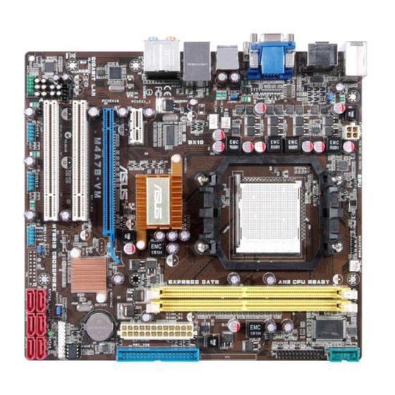
Page 11: Motherboard Overview
15. Digital audio connector (4-1 pin SPDIF_OUT) 1-11 DDR2 DIMM slots 16. Front panel audio connector (10-1 pin AAFP) 1-13 IDE connector (40-1 pin PRI_IDE) 1-12 17. PCI / PCIe x16 slots Onboard LED (SB_PWR) 18. Serial port connector (10-1 pin COM1) 1-15 ASUS M4A78-VM IN/SI... -
Page 12: Central Processing Unit (Cpu)
Central Processing Unit (CPU) This motherboard comes with an AM2+ / AM2 socket designed for AMD Phenom™ x4 / ® Phenom™ x3 / Athlon™ x2 / Athlon™ / Sempron™ processors. It also supports AM3 CPUs including Phenom™ II / Athlon™ x4 / Athlon™ x3 / Athlon™ x2 processors. The AM2+ / AM2 socket has a different pinout from the 940-pin socket designed for the AMD Opteron™... - Page 13 Samsung K4T51083QG-HCF7 M378T6553GZS-CF7 Qimonda · · 1024MB Samsung M378T2953GZ3-CF7 K4T51083QG Samsung · · Super 1024MB Super Talent T800UB1GC4 Heat-Sink Package · · Talent 2048MB Transcend TS256MLQ64V8U E1108ACBG-8E-E Elpida · · 512MB V-Data M2GVD6G3H3160Q1E52 VD29608A8A-25EG20813 VDATA · · ASUS M4A78-VM IN/SI...
- Page 14 • A*: Supports one module inserted into either slot as the single-channel memory configuration. • B*: Supports one pair of modules inserted into both the blue slots as one pair of dual-channel memory configuration. Visit the ASUS website at www.asus.com for the latest QVL. Chapter 1: Product introduction...
-
Page 15: Expansion Slots
The PCI slots support cards such as LAN cards, SCSI cards, USB cards, and other cards that comply with the PCI specifications. 1.5.4 PCI Express x16 slot This motherboard supports PCI Express x16 graphics cards that comply with the PCI Express specifications. ASUS M4A78-VM IN/SI... -
Page 16: Jumpers
Jumpers Clear RTC RAM (3-pin CLRTC) This jumper allows you to clear the Real Time Clock (RTC) RAM in CMOS. You can clear the CMOS memory of date, time, and system setup parameters by erasing the CMOS RTC RAM data. The onboard button cell battery powers the RAM data in CMOS, which include system setup information such as system passwords. - Page 17 This jumper allows you to switch between the HDMI and the DVI features. By default, the HDMI feature is enabled. To enable the DVI feature, set this jumber to pins 2-3. To switch to HDMI, set this jumper to pins 1-2. ASUS M4A78-VM IN/SI...
-
Page 18: Connectors
Connectors 1.7.1 Rear panel ports PS/2 Mouse port (green). This port is for a PS/2 mouse. Video Graphics Adapter (VGA) port. This 15-pin port is for a VGA monitor or other VGA-compatible devices. LAN (RJ-45) port. This port allows Gigabit connection to a Local Area Network (LAN) through a network hub. - Page 19 1280 x 1080p Blu-Ray 1280 x 1080p 1280 x 1080p • To play HD DVD or Blu-Ray disc, ensure to use HDCP compliant devices and software. PS/2 Keyboard port (purple). This port is for a PS/2 keyboard. ASUS M4A78-VM IN/SI 1-10...
-
Page 20: Internal Connectors
1.7.2 Internal connectors Serial ATA connectors (7-pin SATA1, SATA2, SATA3, SATA4) These connectors are for the Serial ATA signal cables for Serial ATA 3Gb/s hard disk and optical disk drives. The Serial ATA 3Gb/s is backward compatible with Serial ATA 1.5Gb/s specification. - Page 21 This prevents incorrect insertion when you connect the IDE cable. • If any device jumper is set as “Cable-Select”, ensure that all other device jumpers have the same setting. • Use the 80-conductor IDE cable for Ultra DMA 133/100/66 IDE devices. ASUS M4A78-VM IN/SI 1-12...
- Page 22 USB connectors (10-1 pin USB56, USB78) These connectors are for USB 2.0 ports. Connect the USB module cable to any of these connectors, then install the module to a slot opening at the back of the system chassis. These USB connectors comply with the USB 2.0 specification that supports up to 480Mbps connection speed.
- Page 23 These are not jumpers! DO NOT place jumper caps on the fan connectors. Only the CPU fan supports the ASUS Q-Fan feature. Chassis intrusion connector (4-1 pin CHASSIS) This connector is for a chassis-mounted intrusion detection sensor or switch. Connect one end of the chassis intrusion sensor or switch cable to this connector.
- Page 24 ATX power connectors (24-pin EATXPWR, 4-pin ATX12V) These connectors are for an ATX power supply. The plugs from the power supply are designed to fit these connectors in only one orientation. Find the proper orientation and push down firmly until the connectors completely fit. •...
- Page 25 BIOS settings. Pressing the power switch for more than four seconds while the system is ON turns the system OFF. • Reset button (2-pin RESET) This 2-pin connector is for the chassis-mounted reset button for system reboot without turning off the system power. ASUS M4A78-VM IN/SI 1-16...
-
Page 26: Software Support
The contents of the Support DVD are subject to change at any time without notice. Visit the ASUS website at www.asus.com for updates. To run the Support DVD Place the Support DVD into the optical drive. -
Page 27: Chapter 2: Bios Information
BIOS in the future. Copy the original motherboard BIOS using the ASUS Update utility. 2.1.1 ASUS Update utility The ASUS Update is a utility that allows you to manage, save, and update the motherboard BIOS in Windows environment. ®... -
Page 28: Asus Ez Flash 2 Utility
2.1.3 ASUS CrashFree BIOS 3 utility The ASUS CrashFree BIOS 3 is an auto recovery tool that allows you to restore the BIOS file when it fails or gets corrupted during the updating process. You can update a corrupted BIOS file using the motherboard Support DVD or a USB flash disk that contains the updated BIOS file. -
Page 29: Bios Setup Program
Start Programming... Restart the system after the utility completes the updating process. • Only a USB flash disk with FAT 32/16 format and single partition supports ASUS CrashFree BIOS 3. The device size should be smaller than 8GB. • DO NOT shut down or reset the system while updating the BIOS! Doing so can cause system boot failure! The recovered BIOS may not be the latest BIOS version for this motherboard. -
Page 30: Main Menu
• The BIOS setup screens in this section are for reference only. They may not exactly match what you see on your screen. • Visit the ASUS website at www.asus.com to download the latest BIOS file for this motherboard. Main menu When you enter the BIOS Setup program, the Main menu screen appears, giving you an overview of the basic system information. -
Page 31: Sata Configuration
LBA/Large Mode [Auto] Enables or disables the LBA mode. Setting to [Auto] enables the LBA mode if the device supports this mode, and if the device was not previously formatted with LBA mode disabled. Configuration options: [Disabled] [Auto] Block (Multi-Sector Transfer) M [Auto] Enables or disables data multi-sectors transfers. -
Page 32: Advanced Menu
Allows you to select the processor frequency. Configuration options: [Auto] [x8.0 1600 MHz] [x8.5 1700 MHz] [x9.0 1800 MHz] [x9.5 1900 MHz] ... [x23.5 4700 MHz] [x24.0 4800 MHz] [x24.5 4900 MHz] [x25 5000 MHz] CPU Prefetching [Enabled] Enables or disables the CPU prefetching. Configuration options: [Enabled] [Disabled] ASUS M4A78-VM IN/SI... -
Page 33: Chipset
C1E Configuration [Disabled] Allows you to enable or disable C1E Dual-Core related CPU power State. Configuration options: [Disabled] [Enabled] 2.4.3 Chipset The Chipset menu allows you to change the advanced chipset settings. Select an item then press <Enter> to display the sub-menu. NorthBridge Configuration Memory Configuration Bank Interleaving [Auto]... -
Page 34: Internal Graphics
Allows you to disable or enable the Surround View function. Configuration options: [Auto] [Disabled] [Enabled] This item becomes user-configurable when you install an ATI graphics card into the PCIe x16 slot. Frame Buffer Location [Above 4G] Configuration options: [Below 4G] [Above 4G] ASUS M4A78-VM IN/SI... -
Page 35: Onboard Devices Configuration
AMD 780 HD Audio [Enabled] Allows you to enable or disable AMD 780 HD audio. Configuration options: [Enabled] [Disabled] 2.4.4 Onboard Devices Configuration Serial Port1 Address [3F8/IRQ4] Allows you to select the Serial Port1 base address. Configuration options: [Disabled] [3F8/IRQ4][2F8/IRQ3] [3E8/IRQ4] [2E8/IRQ3] Onboard HD Audio Controller [Enabled] Allows you to enable or disable the onboard HD Audio Controller. -
Page 36: Power Menu
Allows you to enable or disable the Advanced Configuration and Power Interface (ACPI) support in the Application-Specific Integrated Circuit (ASIC). When set to Enabled, the ACPI APIC table pointer is included in the RSDT pointer list. Configuration options: [Disabled] [Enabled] 2-10 ASUS M4A78-VM IN/SI... -
Page 37: Apm Configuration
2.5.4 APM Configuration Restore on AC Power Loss [Power Off] When set to Power Off, the system goes into off state after an AC power loss. When set to Power On, the system goes on after an AC power loss. Configuration options: [Power On] [Power Off] [Last State] Power On By PME [Disabled] Allows you to enable or disable PME wake from sleep state. -
Page 38: Boot Menu
This allows you to enable or disable the full screen logo display feature. Configuration options: [Disabled] [Enabled] Set this item to [Enabled] to use the ASUS MyLogo 2™ feature. AddOn ROM Display Mode [Force BIOS] Sets the display mode for option ROM. Configuration options: [Force BIOS] [Keep Current] Bootup Num-Lock [On] Allows you to select the power-on state for the NumLock. -
Page 39: Security
2.6.3 Security The Security menu items allow you to change the system security settings. Select an item then press <Enter> to display the configuration options. Change Supervisor Password Select this item to set or change the supervisor password. The Supervisor Password item on top of the screen shows the default Not Installed. -
Page 40: Tools Menu
2.7.1 ASUS EZ Flash 2 Allows you to run ASUS EZ Flash 2. When you press <OK>, a confirmation message appears. Use the left/right arrow key to select between [Yes] or [No], then press <OK> to confirm your choice. See 2.1.2 ASUS EZ Flash 2 utility for details.