Table of Contents
Advertisement
Quick Links
Advertisement
Table of Contents

Related Manuals for Asus M4A79T Deluxe - Motherboard - ATX


Summary of Contents for Asus M4A79T Deluxe - Motherboard - ATX
- Page 1 M4A79T Deluxe...
- Page 2 Product warranty or service will not be extended if: (1) the product is repaired, modified or altered, unless such repair, modification of alteration is authorized in writing by ASUS; or (2) the serial number of the product is defaced or missing.
-
Page 3: Table Of Contents
Special features..................1-2 1.3.1 Product highlights ..................1-2 1.3.2 ASUS unique features ................1-3 1.3.3 ASUS intelligent performance and overclocking features ......1-5 Chapter 2: Hardware information Before you proceed ................... 2-1 Motherboard overview ................2-2 2.2.1 Motherboard layout ..................2-2 2.2.2... -
Page 4: Contents
3.2.1 ASUS Update utility ................... 3-2 3.2.2 Creating a bootable floppy disk ..............3-4 3.2.3 ASUS EZ Flash 2 utility ................3-5 3.2.4 ASUS CrashFree BIOS 2 utility ..............3-6 BIOS setup program .................. 3-7 3.3.1 BIOS menu screen ..................3-7 3.3.2... - Page 5 Cool ‘n’ Quiet!™ Technology ..............4-3 4.3.2 Audio configurations .................. 4-4 4.3.3 ASUS PC Probe II ..................4-5 4.3.4 ASUS Express Gate SSD / ASUS Express Gate ........4-6 4.3.5 ASUS AI Suite .................... 4-7 4.3.6 ASUS EPU ....................4-8 4.3.7 ASUS Q-Fan 2 ...................
- Page 6 RAID configurations ................4-13 4.4.1 RAID definitions ..................4-13 4.4.2 Installing Serial ATA hard disks ..............4-14 4.4.3 RAID configurations............... 4-14 ® Creating a RAID driver disk..............4-20 4.5.1 Creating a RAID driver disk without entering the OS ....... 4-20 4.5.2 Creating a RAID/SATA driver disk in Windows ........
-
Page 7: Notices
Notices Federal Communications Commission Statement This device complies with Part 15 of the FCC Rules. Operation is subject to the following two conditions: • This device may not cause harmful interference, and • This device must accept any interference received including interference that may cause undesired operation. -
Page 8: Safety Information
Safety information Electrical safety • To prevent electrical shock hazard, disconnect the power cable from the electrical outlet before relocating the system. • When adding or removing devices to or from the system, ensure that the power cables for the devices are unplugged before the signal cables are connected. If possible, disconnect all power cables from the existing system before you add a device. -
Page 9: About This Guide
Refer to the following sources for additional information and for product and software updates. ASUS websites The ASUS website provides updated information on ASUS hardware and software products. Refer to the ASUS contact information. Optional documentation Your product package may include optional documentation, such as warranty flyers, that may have been added by your dealer. -
Page 10: Conventions Used In This Guide
Conventions used in this guide To make sure that you perform certain tasks properly, take note of the following symbols used throughout this manual. DANGER/WARNING: Information to prevent injury to yourself when trying to complete a task. CAUTION: Information to prevent damage to the components when trying to complete a task. -
Page 11: M4A79T Deluxe Specifications Summary
3GB. We recommend using a maximum of 3GB system memory if you are using a Windows 32-bit OS. ® ** Refer to www.asus.com for the memory QVL (Qualified Vendors Lists). 4 x PCI Express 2.0 x16 slots with ATI CrossFireX support Expansion slots ™... - Page 12 - EPU - ASUS AI Nap Express Gate ASUS Quiet Thermal Solution: - ASUS Fanless Design: Heat-pipe solution - ASUS Fanless Design: Stack Cool 2 - ASUS Q-Fan 2 ASUS EZ DIY - ASUS Q-Shield - ASUS Q-Connector - ASUS O.C. Profile...
- Page 13 1 x Reset switch BIOS features 8 Mb Flash ROM, AMI BIOS, PnP, DMI 2.0, SM BIOS 2.5, ACPI 2.0a, ASUS EZ Flash 2, CrashFree BIOS 2 WOL by PME, WOR by PME, WOR by Ring, PXE, Manageability Chassis Intrusion...
-
Page 15: Welcome
® The motherboard delivers a host of new features and latest technologies, making it another standout in the long line of ASUS quality motherboards! Before you start installing the motherboard, and hardware devices on it, check the items in your package with the list below. -
Page 16: Special Features
Green ASUS This motherboard and its packaging comply with the European Union’s Restriction on the use of Hazardous Substances (RoHS). This is in line with the ASUS vision of creating environment-friendly and recyclable products/packaging to safeguard consumers’ health while minimizing the impact on the environment. -
Page 17: Asus Unique Features
ASUS 8+2 Phase Power Design To fully unleash the next-generation AM3 CPU's potential, the ASUS M4 Series motherboards have adopted the brand new 8-phase VRM power design, which delivers high power efficiency and supreme overclocking ability. This series’ high quality power components effectively lowers system temperature to ensure longer component lifespan. -
Page 18: Asus Quiet Thermal Solution
DO NOT uninstall the heat-pipe by yourself. Doing so may bend the tubing and affect the heat dissipation performance. Q-Fan 2 ASUS Q-Fan 2 technology intelligently adjusts both CPU fan and chassis fan speeds according to system loading to ensure quiet, cool and efficient operation. ASUS EZ DIY ASUS EZ DIY feature collection provides you easy ways to install computer components, update the BIOS or back up your favorite settings. -
Page 19: Asus Intelligent Performance And Overclocking Features
ASUS intelligent performance and overclocking features TurboV Feel the adrenaline rush of real-time OC—now a reality with the ASUS TurboV. This easy OC tool allows you to overclock without exiting or rebooting the OS; and its user-friendly interface makes overclock with just a few clicks away. Moreover, the ASUS OC profiles in TurboV provides the best O.C. - Page 20 Chapter 1: Product Introduction...
-
Page 21: Before You Proceed
Before you install or remove any component, ensure that the ATX power supply is switched off or the power cord is detached from the power supply. Failure to do so may cause severe damage to the motherboard, peripherals, and/or components. ASUS M4A79T Deluxe... -
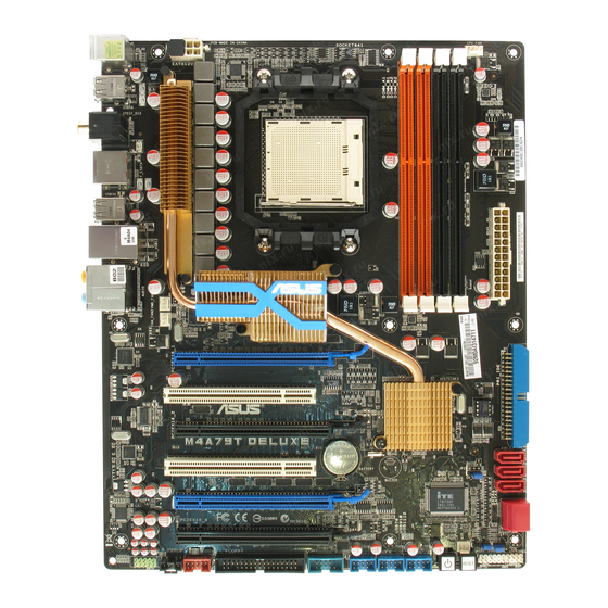
Page 22: Motherboard Overview
Motherboard overview 2.2.1 Motherboard layout Refer to 2.8 Connectors for more information about rear panel connectors and internal connectors. Chapter 2: Hardware information... -
Page 23: Layout Contents
Floppy disk drive connector (34-1 pin FLOPPY) 2-27 IEEE 1394a port connector (10-1 pin IE1394_2) 2-31 Digital audio connector (4-1 pin SPDIF_OUT) 2-27 Optical drive audio connector (4-pin CD) 2-30 Front panel audio connector (10-1 pin AAFP) 2-35 ASUS M4A79T Deluxe... -
Page 24: Placement Direction
2.2.3 Placement direction When installing the motherboard, make sure that you place it into the chassis in the correct orientation. The edge with external ports goes to the rear part of the chassis as indicated in the image below. 2.2.4 Screw holes Place nine (9) screws into the holes indicated by circles to secure the motherboard to the chassis. -
Page 25: Central Processing Unit (Cpu)
Press the lever sideways to unlock the socket, then lift it up to a 90˚ angle. Socket lever Make sure that the socket lever is lifted up to a 90˚ angle. Otherwise, the CPU will not fit in completely. ASUS M4A79T Deluxe... - Page 26 Position the CPU above the socket such that the CPU corner with the gold triangle matches the socket corner with a small triangle. Carefully insert the CPU into the socket until it fits in place. Gold triangle Small triangle When the CPU is in place, push down the socket lever to secure the CPU.
-
Page 27: Installing The Heatsink And Fan
Retention module base Your boxed CPU heatsink and fan assembly should come with installation instructions for the CPU, heatsink, and the retention mechanism. If the instructions in this section do not match the CPU documentation, follow the latter. ASUS M4A79T Deluxe... - Page 28 Attach one end of the retention bracket to the retention module base. Align the other end of the retention bracket to the retention module base. A clicking sound denotes that the retention bracket is in place. Ensure that the fan and heatsink assembly perfectly fits the retention mechanism module base, otherwise you cannot snap the retention bracket...
- Page 29 When the fan and heatsink assembly is in place, connect the CPU fan cable to the connector on the motherboard labeled CPU_FAN. • Do not forget to connect the CPU fan connector! Hardware monitoring errors can occur if you fail to plug this connector. • This connector is backward compatible with old 3-pin CPU fan. ASUS M4A79T Deluxe...
-
Page 30: System Memory
System memory 2.4.1 Overview The motherboard comes with four Double Data Rate 3 (DDR3) Dual Inline Memory Modules (DIMM) sockets. A DDR3 module has the same physical dimensions as a DDR2 DIMM but is notched differently to prevent installation on a DDR2 DIMM socket. DDR3 modules are developed for better performance with less power consumption. -
Page 31: Memory Configurations
To operate at the vendor-marked or at a higher frequency, see section 3.6 Advanced menu for manual memory frequency adjustment. • For system stability, use a more efficient memory cooling system to support a full memory load (4 DIMMs) or overclocking condition. 2-11 ASUS M4A79T Deluxe... - Page 32 M4A79T Deluxe Motherboard Qualified Vendors Lists (QVL) DDR3-1600 MHz capability DIMM socket Chip Timing support Vendor Part No. Size Chip NO. Voltage Brand Dimm (Bios) (Optional) A* B* C* A-DATA AD31600E001GMU(XMP) 3072MB(Kit of 3) SS N/A Heat-Sink Package 8-8-8-24(1333-9-9-9-24) 1.65-1.85 • •...
- Page 33 PDC32G1333LLK 1024MB SS PATRIOT Heat-Sink Package 7(1337-7-7-7-20) • Patriot PVT33G1333ELK 3072MB(Kit of 3) SS N/A Heat-Sink Package 9-9-9-24(1066-7-7-7-20) 1.65 • • • Patriot PVT36G1333ELK 6144MB(Kit of 3) DS N/A Heat-Sink Package 9-9-9-24(1066-7-7-7-20) 1.65 • • • 2-13 ASUS M4A79T Deluxe...
-
Page 34: Memory Configuration
• C*: Supports four modules inserted into both the orange and black slots as two pairs of dual-channel memory configuration. Visit the ASUS website at www.asus.com for the latest QVL. 2-14 Chapter 2: Hardware information... -
Page 35: Installing A Dimm
DIMM. DIMM notch Support the DIMM lightly with your fingers when pressing the retaining clips. The DIMM might get damaged when it flips out with extra force. Remove the DIMM from the socket. 2-15 ASUS M4A79T Deluxe... -
Page 36: Expansion Slots
Expansion slots In the future, you may need to install expansion cards. The following sub-sections describe the slots and the expansion cards that they support. Make sure to unplug the power cord before adding or removing expansion cards. Failure to do so may cause you physical injury and damage motherboard components. -
Page 37: Interrupt Assignments
– shared – – – – USB 2.0 controller – – – shared – – – – HD audio shared – – – – – – – Onboard SATA – – – – shared – – 2-17 ASUS M4A79T Deluxe... -
Page 38: Pci Slots
2.5.4 PCI slots The PCI slots support cards such as a LAN card, SCSI card, USB card, and other cards that comply with PCI specifications. Refer to the figure below for the location of the slots. 2.5.5 Four PCI Express 2.0 x16 slots This motherboard supports four ATI CrossFireX™... - Page 39 If you install two graphics cards to the blue slots and use other x4 PCIe cards simultaneously, the x4 PCIe cards will downgrade to x1 mode for optimum VGA performance. You may reassign PCIe width in BIOS settings. Refer to page 3-22 for details. 2-19 ASUS M4A79T Deluxe...
-
Page 40: Jumpers
Jumpers Clear RTC RAM (3-pin CLRTC) This jumper allows you to clear the Real Time Clock (RTC) RAM in CMOS. You can clear the CMOS memory of date, time, and system setup parameters by erasing the CMOS RTC RAM data. The onboard button cell battery powers the RAM data in CMOS, which include system setup information such as system passwords. - Page 41 OV_CPU jumper, shut down the computer and move the cap back to pins 2-3. • The system may need a better cooling system (for example, a water-cooling system) to work stably under high voltage settings. 2-21 ASUS M4A79T Deluxe...
-
Page 42: Onboard Switches
Onboard switches Onboard switches allow you to power on or reboot system quickly and conveniently when you want to fine- tune performance on a bare or open-case system. Power-on switch Press the power-on switch to wake/power up the system. Reset switch Press the reset switch to reboot the system. -
Page 43: Connectors
PS/2 keyboard port (purple) 11. Audio I/O ports*** USB 2.0 ports 5 and 6 * To use hot-plug, set the OnChip SATA Type in the BIOS settings to [AHCI] mode. See section 3.4.2 Storage Configuration for details. 2-23 ASUS M4A79T Deluxe... -
Page 44: Audio I/O Connections
LAN port LED indications** Left Right Status Left LED Right LED Orange (blinking during 10 Mbps connection data activity) 100 Mbps connection Orange (blinking during data activity) 1 Gbps connection Green (blinking during data activity) LAN port Audio 2, 4, 6, or 8-channel configuration*** Port Headset 4-channel... - Page 45 Connect to Stereo Speakers Connect to 2.1 channel Speakers Connect to 4.1 channel Speakers 2-25 ASUS M4A79T Deluxe...
- Page 46 Connect to 5.1 channel Speakers Connect to 7.1 channel Speakers 2-26 Chapter 2: Hardware information...
-
Page 47: Internal Connectors
This connector is for an additional Sony/Philips Digital Interface (S/PDIF) port(s). Connect the S/PDIF Out module cable to this connector, then install the module to a slot opening at the back of the system chassis. The S/PDIF module is purchased separately. 2-27 ASUS M4A79T Deluxe... - Page 48 IDE connector (40-1 pin PRI_IDE) The onboard IDE connector is for the Ultra DMA 133/100/66 signal cable. There are three connectors on each Ultra DMA 133/100/66 signal cable: blue, black, and gray. Connect the blue connector to the motherboard’s IDE connector, then select one of the following modes to configure your device.
- Page 49 For detailed instructions on how to configure RAID 0, RAID 1, RAID 5 and RAID 10, refer to the RAID manual in the support DVD. • If you intend to create a Serial ATA RAID set using these connectors, set the OnChip SATA Type item in the BIOS to [RAID]. 2-29 ASUS M4A79T Deluxe...
- Page 50 Never connect a 1394 cable to the USB connectors. Doing so will damage the motherboard! You can connect the front panel USB cable to the ASUS Q-Connector (USB, blue) first, and then install the Q-Connector (USB) to the USB connector onboard if your chassis supports front panel USB ports.
- Page 51 This connector is for a serial (COM) port. Connect the serial port module cable to this connector, then install the module to a slot opening at the back of the system chassis. The COM module is purchased separately. 2-31 ASUS M4A79T Deluxe...
- Page 52 These are not jumpers! Do not place jumper caps on the fan connectors! • Only the CPU_FAN, CHA_FAN 1 and CHA_FAN 2 connectors support the ASUS Q-Fan 2 feature. • If you install two VGA cards, we recommend that you plug the rear chassis fan cable to the motherboard connector labeled CHA_FAN1 or CHA_FAN2 for better thermal environment.
- Page 53 By default , the pin labeled “Chassis Signal” and “Ground” are shorted with a jumper cap. Remove the jumper caps only when you intend to use the chassis intrusion detection feature. 2-33 ASUS M4A79T Deluxe...
- Page 54 If you are uncertain about the minimum power supply requirement for your system, refer to the Recommended Power Supply Wattage Calculator at http://support. asus.com/PowerSupplyCalculator/PSCalculator.aspx?SLanguage=en-us for details. • The ATX 12 V Specification 2.0-compliant (1000W) PSU has been tested to support...
- Page 55 Front Panel Type item in the BIOS setup to [HD]; if you want to connect an AC'97 front panel audio module to this connector, set the item to [AC 97]. By default, this item is set to [HD]. 2-35 ASUS M4A79T Deluxe...
-
Page 56: System Panel Connector
System panel connector (20-8 pin PANEL) This connector supports several chassis-mounted functions. • System power LED (2-pin PLED) This 2-pin connector is for the system power LED. Connect the chassis power LED cable to this connector. The system power LED lights up when you turn on the system power, and blinks when the system is in sleep mode. -
Page 57: Asus Q-Connector
ASUS Q-Connector (system panel) Use the ASUS Q-Connector to connect/disconnect the chassis front panel cables. To install the ASUS Q-Connector Connect the front panel cables to the ASUS Q-Connector. Refer to the labels on the Q-Connector to know the detailed pin definitions, and then match them to their respective front panel cable labels. -
Page 58: Starting Up For The First Time
Starting up for the first time After making all the connections, replace the system case cover. Be sure that all switches are off. Connect the power cord to the power connector at the back of the system chassis. Connect the power cord to a power outlet that is equipped with a surge protector. Turn on the devices in the following order: Monitor External SCSI devices (starting with the last device on the chain) -
Page 59: Knowing Bios
® ASUS EZ Flash 2: Updates the BIOS using a floppy disk or USB flash disk. ASUS CrashFree BIOS 2: Updates the BIOS using a bootable floppy disk or the motherboard support DVD when the BIOS file fails or gets corrupted. -
Page 60: Asus Update Utility
3.2.1 ASUS Update utility The ASUS Update is a utility that allows you to manage, save, and update the motherboard BIOS in Windows environment. The ASUS Update utility allows you to: ® • Save the current BIOS file • Download the latest BIOS file from the Internet •... - Page 61 Auto Select. Click Next. Next. Follow the onscreen instructions to complete the update process. The ASUS Update utility is capable of updating itself through the Internet. Always update the utility to avail all its features. Updating the BIOS through a BIOS file...
-
Page 62: Creating A Bootable Floppy Disk
3.2.2 Creating a bootable floppy disk Insert a formatted, high density 1.44MB floppy disk to the floppy disk drive. Follow the instructions based on your system environment. DOS environment a. At the DOS prompt, type format A:/S then press <Enter>. Windows XP environment ®... -
Page 63: Asus Ez Flash 2 Utility
3.2.3 ASUS EZ Flash 2 utility The ASUS EZ Flash 2 feature allows you to update the BIOS without having to use a bootable floppy disk or a DOS-based utility. Before you start using this utility, download the latest BIOS from the ASUS website at www. -
Page 64: Asus Crashfree Bios 2 Utility
3.2.4 ASUS CrashFree BIOS 2 utility The ASUS CrashFree BIOS 2 is an auto recovery tool that allows you to restore the BIOS file when it fails or gets corrupted during the updating process. You can update a corrupted BIOS file using the motherboard support DVD or the floppy disk that contains the updated BIOS file. -
Page 65: Bios Setup Program
For changing the advanced system settings Power For changing the advanced power management (APM) configuration Boot For changing the system boot configuration Tools For configuring options for special functions Exit For selecting the exit options and loading default settings ASUS M4A79T Deluxe... -
Page 66: Navigation Keys
3.3.3 Navigation keys At the bottom right corner of a menu screen are the navigation keys for that particular menu. Use the navigation keys to select items in the menu and change the settings. The navigation keys may differ from one screen to another. 3.3.4 Menu items The highlighted item on the menu bar displays the specific items for that menu. -
Page 67: Main Menu
The BIOS automatically detects the values opposite the dimmed items (Device, Vendor, Size, LBA Mode, Block Mode, PIO Mode, Async DMA, Ultra DMA, and SMART monitoring). These values are not user-configurable. These items show N/A if no IDE device is installed in the system. ASUS M4A79T Deluxe... - Page 68 Type [Auto] Allows you to select the type of IDE drive installed. [Not Installed] Select this option if no IDE drive is installed. [Auto] Allows automatic selection of the appropriate IDE device type. [CDROM] Select this option if you are specifically configuring a CD-ROM drive. [ARMD] Select [ARMD] (ATAPI Removable Media Device) if your device is either a ZIP, LS-120, or MO drive.
-
Page 69: Storage Configuration
When this item is set to [AHCI], only SATA connectors 1–4 can be detected. Ensure that you’ve installed the AHCI driver, so that you could use SATA connectors 1–5 and E-SATA connector in AHCI mode under OS. ASUS M4A79T Deluxe 3-11... -
Page 70: System Information
3.4.3 System Information This menu gives you an overview of the general system specifications. The BIOS automatically detects the BIOS information, CPU specification, and system memory in this menu. BIOS SETUP UTILITY Main BIOS Information Version : 0202 Build Date: 12/09/08 Processor Type : AMD Phenom(tm) 8600 Triple-Core Processor Speed : 2200MHz System Memory Usable Size : 1024MB Ai Tweaker menu The Ai (Extreme) Tweaker menu items allow you to configure overclocking-related items. -
Page 71: Cpu Ratio [Auto]
Allows you to select the HyperTransport link speed. Configuration options: [Auto] [200 MHz] [400 MHz] [600 MHz] [800 MHz] [1 GHz] [1.2 GHz] [1.4 GHz] [1.6 GHz] [1.8 GHz] [2.0 GHz] [2.2 GHz] [2.4 GHz] [2.6 GHz] ASUS M4A79T Deluxe 3-13... -
Page 72: Memory Configuration
3.5.8 Memory Configuration Ai Tweaker Memory Configuration Enable Bank Memory Interleavng. Bank Interleaving [Auto] Channel Interleaving [XOR of Address bit] Enable Clock to All DIMMs [Disabled] MemClk Tristate C3/ATLVID [Disabled] Memory Hole Remapping [Enabled] DCT Unganged Mode [Always] Power Down Enable [Disabled] Page Smashing [Disabled] Bank Interleaving [Auto] Configuration options: [Disabled] [Auto] Channel Interleaving [XOR of Address bit] Configuration options: [Disabled] [Address bits 6] [Address bits 12] [XOR of Address bits [20:16, 6]] [XOR of Address bits [20:16, 9]] Enable Clock to All DIMMs [Disabled] Enables unused clocks to DIMMs even if the memory slots are not populated. -
Page 73: Dram Timing Configuration
Configuration options: [Auto] [4 CLK] [5 CLK] [6 CLK] [7 CLK] DRAM 2nd Information : 5-2-4-45-3-3-90-0 TRWTTO [Auto] Configuration options: [Auto] [3 CLK] [4 CLK] [5 CLK] – [17 CLK] TWRRD [Auto] Configuration options: [Auto] [2 CLK] [3 CLK] [4 CLK] – [10 CLK] ASUS M4A79T Deluxe 3-15... -
Page 74: Cpu Voltage [Auto]
TWTR [Auto] Configuration options: [Auto] [4 CLK] [5 CLK] [6 CLK] [7 CLK] TWRWR [Auto] Configuration options: [Auto] [3 CLK] [4 CLK] [5 CLK] – [10 CLK] TRDRD [Auto] Configuration options: [Auto] [2 CLK] [3 CLK] [4 CLK] – [10 CLK] TRFC0/TRFC01 [Auto] Configuration options: [Auto] [90ns] [110ns] [160ns] [300ns] [350ns] DCT0:CKE drive strength. -
Page 75: Cpu/Nb Voltage [Auto]
3.5.18 CPU Spread Spectrum [Enabled] [Disabled] Enhances the CPU overclocking ability. [Enabled] Set to [Enabled] for EMI control. 3.5.19 PCIE Spread Spectrum [Enabled] [Disabled] Enhances the PCIE overclocking ability. [Enabled] Set to [Enabled] for EMI control. ASUS M4A79T Deluxe 3-17... -
Page 76: Advanced Menu
Advanced menu The Advanced menu items allow you to change the settings for the CPU and other system devices. Be cautious when changing the settings of the Advanced menu items. Incorrect field values can cause the system to malfunction. BIOS SETUP UTILITY Main Ai Tweaker Advanced Power Boot Tools Exit CPU Configuration Configure CPU. - Page 77 Adjusting this item help enhance the processor’s overclocking capability. [Disabled] Disables this function. [Auto] The BIOS automatically adjusts this function. [All Cores] Enables the processor to have the best overclocking performance. [Per Core] Enhances the processor’s overclocking capability. ASUS M4A79T Deluxe 3-19...
-
Page 78: Chipset
3.6.2 Chipset The Chipset menu allows you to change the advanced chipset settings. Select an item then press <Enter> to display the submenu. BIOS SETUP UTILITY Advanced Advanced Chipset Settings Options for NB NorthBridge Configuration RD790 Configuration North Bridge Chipset Configuration BIOS SETUP UTILITY Advanced North Bridge Chipset Configuration Set the ECC options for cache and dram ECC Configuration... -
Page 79: Pci Express Configuration
[Disabled] Disables this function. GPP Slots Power Limit, W [25] Use the <+> and <-> keys to change the value or type the desired value using the numeric keypad. The values range from 0 to 255. ASUS M4A79T Deluxe 3-21... -
Page 80: Onboard Devices Configuration
3.6.3 Onboard Devices Configuration BIOS SETUP UTILITY Advanced On Board Devices Configuration Disabled High Definition Audio [Enabled] Enabled Front Panel Type [HD] SPDIF_OUT Mode Setting [SPDIF Output] Onboard LAN [Enabled] Onboard LAN Boot ROM [Disabled] Firewire 1394 [Enabled] Serial Port1 Address [3F8/IRQ4] High Definition Audio [Auto] [Enabled] Enables the High Definition Audio Controller. [Disabled] Disables the controller. -
Page 81: Usb Configuration
Sets the USB 2.0 controller mode to FullSpeed (12 Mbps). [HiSpeed] Sets the USB 2.0 controller mode to HiSpeed (480 Mbps). BIOS EHCI Hand-off [Enabled] [Enabled] Enables the support for operating systems without an EHCI hand-off feature. [Disabled] Disables the function. ASUS M4A79T Deluxe 3-23... -
Page 82: Pcipnp
3.6.5 PCIPnP The PCIPnP menu items allow you to change the advanced settings for PCI/PnP devices. BIOS SETUP UTILITY Advanced Advanced PCI/PnP Settings NO: lets the BIOS configure all the devices in the system. WARNING: Setting wrong values in below sections YES: lets the may cause system to malfunction. operating system configure Plug and Plug And Play O/S [No] Play (PnP) devices not required for boot if your system has a Plug and Play operating system. Plug And Play O/S [No] [Yes] When set to [Yes] and if you install a Plug and Play operating system, the operating system configures the Plug and Play devices not required for... -
Page 83: Power Menu
When set to [Disabled], the system disable the Advanced Configuration and Power Interface (ACPI) support in the Advanced Programmable Interrupt Controller (APIC). [Enabled] When set to [Enabled], the ACPI APIC table pointer is included in the RSDT pointer list. ASUS M4A79T Deluxe 3-25... -
Page 84: Apm Configuration
3.7.5 APM Configuration BIOS SETUP UTILITY Power APM Configuration Options Restore on AC Power Loss [Disabled] Power On Power On By PME [Disabled] [Disabled] Power Off Power On By PS/2 Keyboard PS/2 Keyboard [Disabled] [Disabled] Last State Power On By PS/2 Mouse PS/2 Mouse [Disabled] [Disabled] Power On By Ring [Disabled] Power On By RTC Alarm [Disabled] Restore On AC Power Loss [Power Off] [Power On] The system goes into on state after an AC power loss. -
Page 85: Hardware Monitor
Sets to [Performance] to achieve maximum CPU fan speed. [Optimal] Sets to [Optimal] to make the CPU fan automatically adjust depending on the CPU temperature. [Silent] Sets to [Silent] to minimize the fan speed for quiet CPU fan operation. ASUS M4A79T Deluxe 3-27... -
Page 86: Boot Menu
Chassis Q-Fan Function [Disabled] [Disabled] Disables the Chassis Q-Fan control feature. [Enabled] Enables the Chassis Q-Fan control feature. Chassis Q-Fan control feature. Q-Fan control feature. The following item appears only when you set Chassis Q-Fan Function to [Enabled]. Quiet Chassis Fan Mode [Silent] [Performance] Sets to [Performance] to achieve maximum chassis fan speed. -
Page 87: Boot Settings Configuration
[Disabled] Disables the full screen logo display feature. Set this item to [Enabled] to use the ASUS MyLogo 2™ feature. AddOn ROM Display Mode [Force BIOS] Sets the display of ROM messages from the BIOS of add-on devices during the boot sequence. -
Page 88: Security
3.8.3 Security The Security menu items allow you to change the system security settings. Select an item then press <Enter> to display the configuration options. BIOS SETUP UTILITY Boot Security Settings <Enter> to change password. Supervisor Password : Not Installed <Enter> again to User Password : Not Installed disable password. Change Supervisor Password Change User Passward Change Supervisor Password Select this item to set or change the supervisor password. The Supervisor Password item on top of the screen shows the default Not Installed. - Page 89 Select this item to clear the user password. Password Check [Setup] [Setup] BIOS checks for user password when accessing the Setup utility. [Always] BIOS checks for user password both when accessing Setup and booting the system. ASUS M4A79T Deluxe 3-31...
-
Page 90: Tools Menu
3.9.1 ASUS EZ Flash 2 Allows you to run ASUS EZ Flash 2. When you press <Enter>, a confirmation message appears. Use the left/right arrow key to select between [Yes] or [No], then press <Enter> to confirm your choice. -
Page 91: Asus O.c. Profile
Express Gate. The first time wizard will run again when you enter the Express Gate environment after clearing its settings. 3.9.3 ASUS O.C. Profile This item allows you to store or load multiple BIOS settings. BIOS SETUP UTILITY Tools O.C. PROFILE Configuration... -
Page 92: Ai Net 2
ASUSTek O.C. Profile Utility V1.34 Current CMOS Restore CMOS BOARD: M4A79T Deluxe BOARD: Unknown VER: 0202 VER: Unknown DATE: 12/09/2008 DATE: Unknown PATH: A:\ Note [Enter] Select or Load [Tab] Switch [V] Drive Info [Up/Down/Home/End] Move [B] Backup [Esc] Exit • This function can support devices such as a USB flash disk or a floppy disk with FAT 32/16 format and single partition only. •... -
Page 93: Exit Menu
When you select this option or if you press <F5>, a confirmation window appears. Select Ok to load default values. Select Exit & Save Changes or make other changes before saving the values to the non-volatile RAM. ASUS M4A79T Deluxe 3-35... - Page 94 3-36 Chapter 3: BIOS setup...
-
Page 95: Installing An Operating System
The contents of the support DVD are subject to change at any time without notice. Visit the ASUS website at www.asus.com for updates. 4.2.1 Running the support DVD Place the support DVD into the optical drive. -
Page 96: Obtaining The Software Manuals
4.2.2 Obtaining the software manuals The software manuals are included in the support DVD. Follow the instructions below to get the necessary software manuals. The software manual files are in Portable Document Format (PDF). Install the Adobe ® Acrobat Reader from the Utilities menu before opening the files. ®... -
Page 97: Software Information
Launching the Cool ‘n’ Quiet!™ software Install Cool ‘n’ Quiet!™ software from the motherboard support DVD. Click Start > All Programs > ASUS > Cool & Quiet > Cool & Quiet. The Cool ‘n’ Quiet!™ technology screen appears and displays the current CPU Frequency and CPU Voltage. -
Page 98: Audio Configurations
Realtek HD Audio Manager for Windows XP Exit button Configuration options Minimize button Control settings window Information button Refer to the software manual in the support DVD or visit the ASUS website at www.asus.com for detailed software configuration. Chapter 4: Software support... -
Page 99: Asus Pc Probe Ii
Launching PC Probe II Install PC Probe II from the motherboard support DVD. Launch PC Probe II by clicking Start > All Programs > ASUS > PC Probe II > PC Probe II v1.xx.xx. The PC Probe II main window appears. -
Page 100: Asus Express Gate Ssd / Asus Express Gate
4.3.4 ASUS Express Gate SSD / ASUS Express Gate ASUS Express Gate SSD / ASUS Express Gate is an instant-on environment that gives you quick access to the Internet, Skype, and your pictures. Within a few seconds of powering on your computer, you will be at the Express Gate SSD / Express Gate menu where you can start the web browser, Skype, or other Express Gate SSD / Express Gate applications. -
Page 101: Asus Ai Suite
Launching AI Suite Install AI Suite from the motherboard support DVD. Launch AI Suite by clicking Start > All Programs > ASUS > AI Suite > AI Suite v1.xx. xx. The AI Suite main window appears. The AI Suite icon appears in the Windows notification area. -
Page 102: Asus Epu
4.3.6 ASUS EPU ASUS EPU is an energy-efficient tool that provides you with a total system power-saving solution. It detects the current computer loading and intelligently adjusts the power in real- time. With auto phase switching for components, the EPU automatically provides the most... -
Page 103: Asus Q-Fan 2
4.3.7 ASUS Q-Fan 2 This ASUS Q-Fan 2 Control feature allows you to set the appropriate performance level of the CPU Q-Fan 2 or the Chassis Q-Fan 2 for more efficient system operation. After enabling the Q-Fan 2 function, the fans can be set to automatically adjust depending on the temperature, to decrease fan speed, or to achieve the maximum fan speed. -
Page 104: Asus Ai Nap
4.3.8 ASUS AI Nap ASUS AI Nap allows you to minimize the power consumption of your computer whenever you are away. Enable this feature for minimum power consumption and a more quiet system operation. Using ASUS AI Nap After installing ASUS AI Suite from the... -
Page 105: Asus Turbov
• For system stability, all changes made in ASUS TurboV will not be saved to BIOS settings and will not be kept on the next system boot. Use the Save Profile function to save your customized overclocking settings and manually load the profile after Windows starts. -
Page 106: Asus Turbo Key
4.3.10 ASUS Turbo Key ASUS Turbo Key allows the user to turn the PC power button into a physical overclocking button. After the easy setup, Turbo Key can boost performances without interrupting ongoing work or games—with just one touch! Launching ASUS Turbo Key Install ASUS AI Suite from the motherboard support DVD. -
Page 107: Raid Configurations
RAID driver from the support DVD to a floppy disk before you install an operating system to a selected hard disk drive. Refer to section 4.5 Creating a RAID driver disk for details. ASUS M4A79T Deluxe 4-13... -
Page 108: Installing Serial Ata Hard Disks
4.4.2 Installing Serial ATA hard disks The motherboard supports Serial ATA hard disk drives. For optimal performance, install identical drives of the same model and capacity when creating a disk array. To install the SATA hard disks for a RAID configuration: Install the SATA hard disks into the drive bays. - Page 109 • Delete LD: deletes a selected RAID set and partition. • Controller Configuration: Shows the system resources configuration. Press <1>, <2>, <3>, or <4> to enter the option you need; press <ESC> to exit the utility. ASUS M4A79T Deluxe 4-15...
- Page 110 Creating a RAID 0 configuration To create a RAID 0 set: In the Main Menu, press <2> to enter the “Define LD” function. Press <Enter>, and the following screen appears. FastBuild (tm) Utility (c) 2004-2005 ATI Technology, Inc. [ Define LD Menu ] LD No RAID Mode Total Drv LD 1 RAID 0 2 Strip Block: 64 KB Fast Init: OFF Gigabyte Boundary: ON...
- Page 111 ---- ---- ---- LD 3 ---- ---- ---- ---- LD 4 ---- ---- ---- ---- LD 5 ---- ---- ---- ---- LD 6 ---- ---- ---- ---- LD 7 ---- ---- ---- ---- LD 8 ---- ---- ---- ---- [ Keys Available ] [↑]Up [↓]Down [ESC]Exit [Enter] Select ASUS M4A79T Deluxe 4-17...
- Page 112 Creating a RAID 10 configuration To create a RAID 10 set: In the Main Menu, press <2> to enter the “Define LD” function. Press <Enter>, and the following screen appears. FastBuild (tm) Utility (c) 2004-2005 ATI Technology, Inc. [ Define LD Menu ] LD No RAID Mode Total Drv LD 1 RAID 10 4 Strip Block: 64 KB Fast Init: OFF Gigabyte Boundary: ON...
-
Page 113: Deleting A Raid Configuration
---- ---- ---- LD 4 ---- ---- ---- ---- LD 5 ---- ---- ---- ---- LD 6 ---- ---- ---- ---- LD 7 ---- ---- ---- ---- LD 8 ---- ---- ---- ---- [ Keys Available ] [↑]Up [↓]Down [ESC]Exit [Del or Alt+D] Delete ASUS M4A79T Deluxe 4-19... -
Page 114: Creating A Raid Driver Disk
Creating a RAID driver disk A floppy disk with the RAID driver is required when installing Windows XP operating system ® on a hard disk drive that is included in a RAID set. For Windows Vista™ operating system, use either the motherboard support DVD or a USB ®... -
Page 115: Ati ® Crossfirex™ Technology
For Windows XP, go to Control Panel > Add/Remove Programs. For Windows Vista, go to Control Panel > Programs and Features. Select your current graphics card drivers. For Windows XP, select Add/Remove. For Windows Vista, select Uninstall. Turn off your computer. ASUS M4A79T Deluxe... -
Page 116: Installing Crossfirex™ Graphics Cards
Installing CrossFireX™ graphics cards • Ensure that your power supply unit (PSU) can provide at least the minimum power required by your system. • We recommend that you install additional chassis fans for better thermal environment. • Install only the identical CrossFireX-ready graphics cards that are ATI -certified. -
Page 117: Triple Crossfirex Installation
Ensure that the connectors are firmly in place. Connect three independent auxiliary power sources from the power supply to the three graphics cards separately. Connect a VGA or a DVI cable to the graphics card. ASUS M4A79T Deluxe... -
Page 118: Quad Crossfirex Installation
5.2.3 Quad CrossFireX installation Prepare four CrossFireX-ready graphics cards. Insert the four graphics card into the PCIEX16 slots. Ensure that the cards are properly seated on the slots. Align and firmly insert the three CrossFireX bridge connectors to the goldfingers on each graphics card. Ensure that the connectors are firmly in place. -
Page 119: Software Information
ATI icon in the Windows notification area and select Cayalyst Control Center. The Catalyst Control Center Setup Assistant appears when the system detects the existance of multi-graphics cards. Click Go to continue to the Catalyst Control Center Advanced View window. ASUS M4A79T Deluxe... - Page 120 Enabling Dual CrossFireX technology In the Catalyst Control Center window, click Graphics Settings > CrossFireX > Configure. From the Graphics Adapter list, select the graphics card to act as the display GPU. Select Enable CrossFireX. Click Apply, and then click OK to exit the window.