Brother KE-436C Instruction Manual
Electronic lockstitch pattern tacker with stepping foot and programming function
Hide thumbs
Also See for KE-436C:
- Parts manual (72 pages) ,
- Specifications (8 pages) ,
- Instruction manual (228 pages)

Related Manuals for Brother KE-436C


Summary of Contents for Brother KE-436C
- Page 1 KE-436C INSTRUCTION MANUAL Please read this manual before using the machine. Please keep this manual within easy reach for quick reference. ELECTRONIC LOCKSTITCH PATTERN TACKER WITH STEPPING FOOT AND PROGRAMMING FUNCTION...
-
Page 2: Safety Instructions
··········· This symbol ( ) indicates something that you must do. The picture inside the circle indicates the nature of the thing that must be done. (For example, the symbol at left means “you must make the ground connection”.) KE-436C... - Page 3 Keep the oil out of the reach of children. Be sure to connect the ground. If the ground connec- tion is not secure, you run a high risk of receiving a serious electric shock, and problems with correct operation may also occur. KE-436C...
- Page 4 Disconnect the air hoses from the air supply and wait covered by the warranty. for the needle on the pressure gauge to drop to “0” before carrying out inspection, adjustment and repair of any parts which use the pneumatic equipment. KE-436C...
-
Page 5: Warning Labels
Be sure to connect the ground. If the ground connection is not secure, you run a high risk of receiving a serious electric shock, and problems with correct operation may also occur. Direction of operation Thread take-up Frame cover side cover 2670Q Belt cover Thread take-up solenoid cover Eye guard Finger guard 2747Q KE-436C... -
Page 6: Table Of Contents
6-1. Selecting the needle and thread ......29 TO SUBCLASSES ........6-2. Installing the needle..........29 15. TROUBLESHOOTING ......6-3. Threading the upper thread ........29 6-4. Winding the lower thread........30 16. OPTIONAL PARTS ........6-5. Replacing the bobbin case and threading the thread ..........31 KE-436C... -
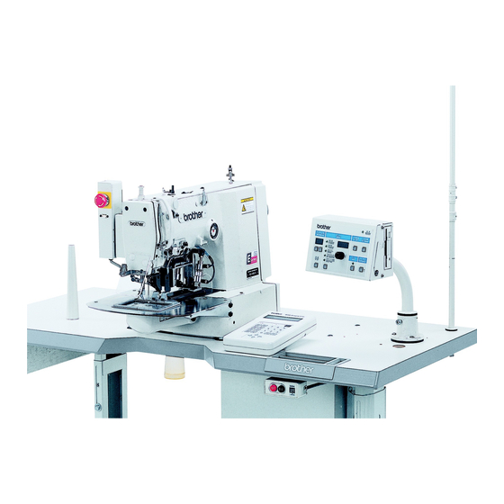
Page 7: Name Of Each Part
(23) Thread take-up solenoid cover (7) Programmer (8) Floppy drive (9) EMERGENCY STOP switch (10) Pulley (11) Spool stand (12) Thread take-up lever (13) Wiper solenoid cover (14) Thread wiper switch (15) Dip switch (16) Integrater (17) Solenoid valve KE-436C... -
Page 8: Specifications
Patterns up to a maximum size of 100 mm 60 mm can be sewn. For plain stitching of small articles, curtain darts, etc. Two-stage work clamp, light work clamp and inner clamping device (optional) can be used. For attaching items, sewing labels, etc. KE-436C... -
Page 9: Installation
If the distance A between the insides of the legs is less than 740 mm, move the control box installation position to the left (B = 247 mm). Check that the control box is at least 10 mm away from the leg. If the control box and leg are touching, it could cause the sewing machine to operate incorrectly. 1090Q KE-436C... -
Page 10: Installing The Control Box
* The main P.C. board mounting plate (3) will be opened again during “3-13. Connecting the cords”, so provisionally tighten it with the screw (1). 4. Install the power switch (8) with the two screws (9). 5. Secure the power switch cord with the three staples (10). KE-436C... -
Page 11: Installing The Rubber Cushions
Place the two cushions (1) into the holes in the work table so that the notches are aligned with the tabs in the oil pan, and secure them in place with the nails (2). * Install so that the head of the nail dose not protrude from the rubber surface. 2492Q KE-436C... -
Page 12: Installing The Switching Plate
3. Install the hinge presser (6) with the two bolts and two nuts. 4. Check that the head position switch is turned on as shown in Figure 1. 5. Connect the motor cord connector (7) to the accessory cord connector (8). KE-436C... -
Page 13: Installing The Head Rest
4. Insert the cord into the control box through the hole at the side of the box. Refer to “3-13. Connecting the cords” for details on connecting the cord. 5. Secure the cord with the staples (in five places). 2673Q KE-436C... -
Page 14: Installing The Programmer (Option)
Be sure to connect the ground. If the ground connection is not secure, you run the risk of receiving a serious electric shock, and problems with correct operation may also occur. Connect to the power switch. However, the black wire is insulated to the inside of the box and is not used. Connect to ground 2741Q KE-436C... -
Page 15: Connecting The Cords
3. INSTALLATION 3-13. Connecting the cords 2502Q 2677Q 2678Q 2748Q KE-436C... - Page 16 11. Tighten the cover (main P.C. board mounting plate (4)) with the six screws (3). Note: Check that the cords do not come into contact with the fan (14) and that they are not clamped by the cover at this time. KE-436C...
-
Page 17: Piping
Connect air tubes in accordance with the identified numbers in the figure, and then bind them with some fastening bands. Be sure not to crush the air tubes at that time. * Light work clamp mode can be used by changing over the air tube connections. (Refer to “12. Setting the work clamp mode”.) KE-436C... - Page 18 When the power is turned off, the work clamps can be operated by pressing the switch. Note: Adjust the control knobs so that the left and right work clamps both operate at the same speed. (Valve 1 and 2) Adjust the control knobs so that the stepping work clamp operates more quickly. (Valve 3) KE-436C...
-
Page 19: Installing The Belt Cover
KE-436C... -
Page 20: Installing The Needle Sub Plate
(6). 2600Q 5. Provisionally secure the two auxiliary plate supports (7) with the washers (8) and the screws (9) and (10), and then firmly tighten the screws (9) and (10) in that order. 2601Q KE-436C... -
Page 21: Installing The Spool Stand
3-19. Installing the eye guard CAUTION Attach all safety devices before using the sewing machine. If the machine is used without these devices attached, injury may result. Install the eye guard assy (1) to the face plate with the two screws (2). 2684Q KE-436C... -
Page 22: Lubrication
4. If using the liquid cooling tank (2), fill it with silicon oil * When setting up the sewing machine and when it (100 mm /s). hasn’t been used for an extended period of time, be sure to add 2-3 drops oil to the felt. KE-436C... -
Page 23: Using The Operation Panel
(7) X-SCALE indicator....Illuminates when X-scale mode has been selected using the menu switch (6). (8) Y-SCALE indicator....Illuminates when Y-scale mode has been selected using the menu switch (6). (9) SPEED indicator ....Illuminates when speed mode has been selected using the menu switch (6). KE-436C... - Page 24 (16) TEST indicator ....... Lights when the TEST switch is pressed. (17) STEP BACK switch....Used when winding a fresh bobbin, or when correcting a stitch pattern due to a broken (RESET switch) needle thread. Also used to reset error displays. KE-436C...
-
Page 25: Using The Floppy Disk
20,000 stitches BAS-300E data can be used when sewing with the KE-436C, but the data resolution will be limited to 0.1 mm per pulse. The above four types of data can all be read, but when writing to disk, all data is automatically converted to BAS-300E data when writing to 2HD disks and BAS-300A data when writing to 2DD disks. - Page 26 Next time you clean it, select a different number. 3. After the cleaning is completed, the “E.4F” error appears. The error appears because the cleaning disk has no data. This is normal. 4. Cancel the error and eject the cleaning disk. KE-436C...
-
Page 27: Using The Program R/W (Read/Write) Switch
2. Press the STEP BACK (RESET) switch (8) on the operation panel (when memory switch No. 0d is ON). If memory switch No. 0d is OFF, press the EMERGENCY STOP switch (6) once more to release it. 2695Q KE-436C... -
Page 28: Operating The Foot Switch
If the work clamp was stopped too late, press the STEP BACK switch (17) to advance the work clamp one stitch at a time. Resuming operation from a stopping point 6. Sewing will start when the start switch (1) is pressed. 2697Q KE-436C... -
Page 29: Using The Emergency Stop Switch
4. After you have reached the desired position, depress the start switch to start sewing. Start switch 1080Q 5-7. Using the thread wiper switch The thread wiper can be turned on and off using the thread wiper switch (1). 2608Q KE-436C... -
Page 30: Adjusting The Sewing Speed Control
2. While pressing the STEP BACK switch (17), turn the dial (12) until the desired ratio flashes on the display. The scale setting is displayed as a percentage. 3. The program number will flash, and after the home position is detected the flashing will stop. 2702Q KE-436C... -
Page 31: Using The Bobbin Thread Counter
(The sewing machine will not start even if the start switch is pressed.) 5. Press the bobbin thread change switch (14) and replace the bobbin. The alarm will stop, and the number of work pieces set in step 3 will be displayed again in the counter (5). KE-436C... -
Page 32: Using Production Counter
2. Depress the start switch to start embroidering. 3. Press the TEST switch (15) or the MENU switch (6). The TEST indicator (16) will switch off and the contents of each display screen will return to the normal display. KE-436C... -
Page 33: Using Single Split Mode
“1” “2” ... 4. When the start switch is pressed, only the pattern displayed on the display screen (5) will be sewn. Note: As to split sewing, refer to the instruction manual of the “electronic programmable pattern tacker programmer” KE-436C... -
Page 34: Shifting A Stitch Pattern
When moving the stitch pattern, the sewing start position can be moved to any desired point within the sewing area, but if the pattern goes outside the sewing area, an error will occur during sewing and you will not be able to sew the pattern. Give consideration to the pattern as a whole when moving it. KE-436C... -
Page 35: Correct Use
Thread the upper thread correctly as shown in the illustration below. [Two holes] [One hole] Spun rayon yarn 2711Q 2708Q [When using the liquid cooling tank] Synthetic thread Approx. 40mm 2709Q 0102Q 2710Q KE-436C... -
Page 36: Winding The Lower Thread
* If the thread winds on as shown in A, turn the bobbin winder thread tension stud (7) clockwise; if it winds on as shown in B, turn the bobbin winder thread tension stud (7) counterclockwise. Case B 2532Q KE-436C... -
Page 37: Replacing The Bobbin Case And Threading The Thread
Thread take-up spring tension (N) 0.15 - 0.35 0.4 - 0.6 Pre-tension (N) 0.1 - 0.3 0.3 - 0.5 Needle 5 #14 17NY #19 The sewing conditions given in the above table may need to be changed depending on the article being sewn. KE-436C... - Page 38 Furthermore, turn the thread nut (2) (sub-tension) to adjust the remaining length of upper thread to 35 - 40 mm, when the thread take-up lever is not used. Stronger Weaker Stronger Weaker 2714Q KE-436C...
- Page 39 (3). * To reduce the thread take-up amount, move the stopper (2) downward. * To increase the thread take-up amount, move the stopper (2) upward. Become greater Become less 2717Q KE-436C...
-
Page 40: Sewing
(4) will show a “P” while the data is being read. When reading is completed, an alarm will sound and the indicator will go out, then the program no. display (4) will blink the program number. 2718Q 2719Q KE-436C... - Page 41 2720Q Note: When the power is turned on after once being turned off, the same pattern of sewing can be continued since the machine will stores the sewing data from the last time. KE-436C...
-
Page 42: Maintenance And Inspection
(2) and the shuttle hook (3). 2548Q 3. Clean all the dust and thread ends from around the driver (4), the top of the rotary hook thread guide and the shuttle race. 2549Q KE-436C... -
Page 43: Lubrication
* When setting up the sewing machine and when it hasn’t been used for an extended period of time, be sure to add 2-3 drops oil to the felt. 2512Q 4. If using the liquid cooling tank (2), fill it with silicon oil (100 /s). 2513Q KE-436C... -
Page 44: Draining The Oil
In addition, be careful not to let any foreign matter get into the air holes. 2463Q 8-7. Cleaning the eye guard Wipe the eye guard clean with a soft cloth. Note: Do not use solvents such as kerosene or thinner to clean the eye guard. 1235S KE-436C... -
Page 45: Standard Adjustments
(reference line B) is aligned with the lower edge of the needle bar bush (1). Then loosen the screw (2) and move the driver (3) to adjust so that the tip of the rotary hook is aligned with the needle center line. * If using a DP 5 needle, use the second reference line from the top of the needle (reference line b). KE-436C... -
Page 46: Adjusting The Driver Needle Guard
If the shuttle race thread guide is in the wrong position, thread breakages, soiled thread or catching of the thread may occur. The position of the shuttle race thread guide is adjusted at the time of shipment from the factory. It should not be changed if at all possible. KE-436C... -
Page 47: Adjusting The Thread Take-Up Amount
If the sub-thread tension is too high, the needle thread length may become too short and the thread may come out of the needle. Furthermore, if the sub-thread tension is too weak, the needle thread length may become too long and the underside of the article being sewn may become untidy. KE-436C... -
Page 48: Adjusting The Movable Knife
4. Loosen the nut (6) and move the connecting rod lever (7) to the left or right to adjust so that the V section A is aligned with the index mark B on the needle plate when in this condition (the procedure 3.) and the movable knife (5) is pushed to the machine pulley side so that there is no play. KE-436C... - Page 49 5. Install the fixed knife (9) at a distance of 0.5 mm from the needle hole plate (12). 6. Place the thread trimming connecting rod (6) onto the connecting rod lever pin (7), and then install to the needle plate (5). KE-436C...
-
Page 50: Adjusting The Work Clamp Lift Amount
* If movement is sluggish when the work clamp (1) is being raised and lowered, it may not be possible to increase the work clamp (1) lift amount. Apply grease to the sliding part of the work clamp (1) (grease is already applied at the time of shipment), and check that the movement becomes easier. KE-436C... -
Page 51: Work Clamp Adjustment
If vertical movement of the work clamp is not required 1. Remove the face plate (10). 2. Remove the stud screw (11) and re-attach the stepping connecting rod (12) to the upper screw hole (14) of the stepping work clamp arm (F) (13). 2628Q 2629Q KE-436C... -
Page 52: Work Clamp Interchangeability
9-11. Work clamp interchangeability 2619Q The BAS-311E, 311F work clamp can also be used with the KE-436C. Replace the feed bar guide cover (1) with the feed bar guide cover assembly, LL (2) (optional). Then, change the installation position for the presser arm assembly (3) from the standard installation position A to installation position B. -
Page 53: Adjusting The Thread Wiper
2. If water stands in the bottle of the integrator (1), turn the drain cock (3) in the direction indicated by an arrow to drain the water. Note: Open the air cock (4) slowly. 2728Q KE-436C... -
Page 54: Checking The Input Sensor And Dip Switch Input
5. Press the TEST switch (2). The display will return to normal. Note: You need to move the DIP switch while the power is still turned on in order to check the DIP switch operation. However, the power must always be turned off before DIP switch settings can be changed. KE-436C... -
Page 55: Checking The Input Voltage
While pressing the R/W switch (1), turn on the power. This will clear all of the memory setting. Note: This operation causes memory switch settings to be returned to their initial settings, and also clears all contents of the memory such as user programs. 2732Q KE-436C... -
Page 56: Dip Switch
8 to 14. DIPB-5 When a fiber-type thread breakage detector device is used, detection precision is increased from 5 to 10. Fiber-type thread breakage detector device is ON, and DIP switch A-8 is ON (available as an DIPB-6 option). DIPB-7 DIPB-8 KE-436C... -
Page 57: Dip Switches Inside The Control Box
When the motor operates in reverse to raise the needle, the thread take-up will stop at a position which is lower than its normal stopping position. As a result, the thread take-up will rise slightly at the sewing start, and this may result in the thread pulling out under certain conditions. KE-436C... -
Page 58: Changing Special Functions Using The Memory Switches
6. Once the program data has been read from the floppy disk, change to memory switch setting mode and then press the B.T. SET switch (7). The buzzer will sound twice, and the current memory switch settings will be written to the floppy disk. KE-436C... - Page 59 Changes the split number automatically by using an external switch. (Use option connector memo-1E P3 on the operation panel.) Program number is changed automatically by using outside switch. (Use optional memo-1F connector P3 on the operation panel.) : OFF KE-436C...
- Page 60 Work clamp lifting and lower thread winding before home position detection are disabled. memo-2A memo-2b memo-2c memo-2d memo-2E When the input voltage is being checked, the display shows the temperature of the heat sink memo-2F on the main circuit board instead of the voltage. : OFF KE-436C...
- Page 61 0 - 3 1: Read as BAS-311A data 2: Read as BAS-326A data 3: Read as BAS-341A, 342A data ex. Read BAS-326A data by KE-436C Set memo-37=2. memo-38 Changes the reference point for enlargement and reduction using the operation panel.
-
Page 62: Setting The Work Clamp Mode
When memo-3b has been used to make a special setting, DIP switches A-1 and A-2 function as follows. When DIP switch A-1 is at ON, the pressers are not raised automatically at the sewing end. DIP switch A-2 is ignored except when memo-3b = 8, 11, 12. KE-436C... -
Page 63: Light Work Clamp
Branch: 1B mode Plug: 2B Both pressers lower, but only left presser lowers in light work Branch: 2A clamp mode Plug: 1A Both pressers lower, but only right presser lowers in light work Branch: 2A clamp mode Plug: 1A KE-436C... -
Page 64: Table Of Error Codes
E.41 Invalid program No., or no data. Change program No. E.43 Different floppy disk! Use original floppy disk. E.4F Error occurred during floppy disk data reading. Replace the floppy disk and repeat the operation. KE-436C... - Page 65 Incorrect connection of cable between power E.F1 Turn off power and check connector P20. supply PCB and main PCB. E.F2 Overcurrent at power supply PCB. Turn off power and check it. REFERENCE segment LED alphabet Panel display Text display KE-436C...
-
Page 66: Gauge Parts List According To Subclasses
159612-001 A 154342-001 B S15667-001 LA Bobbin 159613-051 154663-001 B S44633-001 LAN Shuttle hook, W/BOX 152685-903 A 152687-902 B S59161-991 LF S59162-991 LG Shuttle race body 152682-101 A 152686-101 B Spring tension 104525-001 107606-001 S06548-001 C Spring 145519-001 144588-001 B KE-436C... - Page 67 Each work clamp pair is used in combination with the feed plate directly below them. Work clamps R, L and feed plate 153493-001 S23377-001 (519) S27836-001 (895) 156085-001 (M) 153498-001 S23378-001 (519) S27837-001 (895) 156086-001 (M) Work clamp 153503-001 S23379-001 (519) S27838-001 (895) 156087-001 (M) Feed plate KE-436C...
- Page 68 156088-001 (S) 156083-001 (L) 156089-001 (S) Work clamp 156084-001 (L) 156090-001 (S) Feed plate Gauge assy, 434E MK2 S54984-001 Home position standard plate Needle hole plate S10211-001 S51449-001 S41013-001 S29997-001 S10212-101 S30925-001 S10213-001 S30926-001 S49980-001 S30450-001 S25127-001 S34348-001 S40217-001 KE-436C...
-
Page 69: Troubleshooting
Refer to “Skipped stitches Refer to “Skipped stitches threaded. the sewing start. occur” occur” Uneven upper thread Upper thread length Adjust the sub-tension. length. Thread take-up lever Adjust the thread take-up Upper thread is too short. stroke lever stroke. KE-436C... - Page 70 Needle is touching the rotary hook. Adjust the needle bar lift Needle bar lift amount. amount. Needle is bent. Bent needle Replace the needle. Use the correct needle Needle is too thin. Needle and thread for the material. KE-436C...
-
Page 71: Adjust The Position Of The
9, 10 operate when power is connection disconnected. turned foot switch is depressed. Head position switch Adjust the position of the Switching plate position does not work. switching plate. Head position switch is Replace the head posi- broken. tion switch. KE-436C... -
Page 72: Optional Parts
Use according to particular sewing needs in order to provide an even clamping force. Programmer assy Used to create sewing patterns for the KE-436C. It can also be used to display error messages. Thread breakage detector device Available as rotary type or fiber type, stops sewing when a thread breakage is detected and warns the operator. -
Page 73: Instruction Manual
INSTRUCTION MANUAL 15-1, Naeshiro-cho, Mizuho-ku, Nagoya 467-8561, Japan. Phone: 81-52-824-2177 Printed in Japan 118-P34 S91P34-102 2002.10.B(1)