Table of Contents
Advertisement
Advertisement
Table of Contents

Related Manuals for Asus P7P55-M


Summary of Contents for Asus P7P55-M
- Page 1 P7P55-M...
- Page 2 Product warranty or service will not be extended if: (1) the product is repaired, modified or altered, unless such repair, modification of alteration is authorized in writing by ASUS; or (2) the serial number of the product is defaced or missing.
-
Page 3: Table Of Contents
Welcome! ..................1-1 Package contents ................. 1-1 Special features ................1-1 1.3.1 Product highlights ............1-1 1.3.2 Innovative ASUS features ..........1-2 Before you proceed ..............1-5 Motherboard overview ..............1-6 1.5.1 Placement direction ............1-6 1.5.2 Screw holes ..............1-6 1.5.3... - Page 4 BIOS information Managing and updating your BIOS ..........2-1 2.1.1 ASUS Update utility ............2-1 2.1.2 ASUS EZ Flash 2 utility ........... 2-2 2.1.3 ASUS CrashFree BIOS ........... 2-3 2.1.4 ASUS BIOS Updater ............2-4 BIOS setup program ..............2-7 Main menu ..................
- Page 5 Boot Settings Configuration .......... 2-22 2.7.3 Security ................. 2-23 Tools menu ................. 2-25 2.8.1 ASUS O.C. Profile ............2-25 2.8.2 AI NET 2................ 2-26 2.8.3 ASUS EZ Flash 2 ............2-26 2.8.4 Express Gate ..............2-26 Exit menu ..................2-27...
-
Page 6: Notices
Complying with the REACH (Registration, Evaluation, Authorisation, and Restriction of Chemicals) regulatory framework, we published the chemical substances in our products at ASUS REACH website at http://green.asus.com/english/REACH.htm. DO NOT throw the motherboard in municipal waste. This product has been designed to enable proper reuse of parts and recycling. -
Page 7: Safety Information
Safety information Electrical safety • To prevent electric shock hazard, disconnect the power cable from the electric outlet before relocating the system. • When adding or removing devices to or from the system, ensure that the power cables for the devices are unplugged before the signal cables are connected. If possible, disconnect all power cables from the existing system before you add a device. -
Page 8: About This Guide
Refer to the following sources for additional information and for product and software updates. ASUS websites The ASUS website provides updated information on ASUS hardware and software products. Refer to the ASUS contact information. Optional documentation Your product package may include optional documentation, such as warranty flyers, that may have been added by your dealer. -
Page 9: P7P55-M Specifications Summary
1800(O.C.)/1600/1333 /1066MHz memory modules * Supports Intel Extreme Memory Profile (XMP) ® ** Refer to www.asus.com for the latest Memory QVL (Qualified Vendors List). *** When you install a total memory of 4GB or more, Windows 32-bit operating system may only recognize less ®... - Page 10 1MHz increment - PCI Express frequency tuning from 100MHz up to 160MHz at 1MHz increment Overclocking Protection: - ASUS C.P.R.(CPU Parameter Recall) Back panel I/O ports 1 x PS/2 keyboard/mouse combo port 1 x COM port 1 x IEEE1394 1 x LAN (RJ-45) port 8 x USB 2.0/1.1 ports...
-
Page 11: Chapter 1: Product Introduction
® The motherboard delivers a host of new features and latest technologies, making it another standout in the long line of ASUS quality motherboards! Before you start installing the motherboard, and hardware devices on it, check the items in your package with the list below. -
Page 12: Innovative Asus Features
1.3.2 Innovative ASUS features Turbo Key ASUS Turbo Key allows you to turn the PC power button into a physical overclocking button. After the easy setup, Turbo Key can boost performances without interrupting ongoing work or games—with just one touch! -
Page 13: Asus Express Gate
BIOS file using the bundled support DVD or USB flash disk that contains the latest BIOS file. ASUS EZ Flash 2 ASUS EZ Flash 2 is a utility that allows you to update the BIOS without using an OS-based utility. ASUS AI NET2... - Page 14 This motherboard and its packaging comply with the European Union’s Restriction on the use of Hazardous Substances (RoHS). This is in line with the ASUS vision of creating environment-friendly and recyclable products/packaging to safeguard consumers’ health while minimizing the impact on the environment.
-
Page 15: Before You Proceed
ON, in sleep mode, or in soft-off mode. This is a reminder that you must shut down the system and unplug the power cable before removing or plugging in any motherboard component. The illustration below shows the location of the onboard LED. SB_PWR P7P55-M Standby Power Powered Off P7P55-M Onboard LED ASUS P7P55-M... -
Page 16: Motherboard Overview
Motherboard overview Before you install the motherboard, study the configuration of your chassis to ensure that the motherboard fits into it. Ensure that you unplug the power cord before installing or removing the motherboard. Failure to do so can cause you physical injury and damage motherboard components. 1.5.1 Placement direction When installing the motherboard, ensure that you place it into the chassis in the correct... -
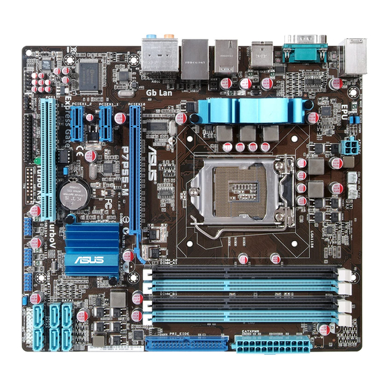
Page 17: Motherboard Layout
13. LPT connector (26-1 pin LPT) 1-28 DDR3 DIMM sockets 1-13 14. Digital audio connector (4-1 pin SPDIF_OUT) 1-26 7. IDE connector (40-1 pin PRI_EIDE) 1-25 15. Front panel audio connector (10-1 pin AAFP) 1-24 Serial ATA connectors (7-pin SATA1-6) 1-28 ASUS P7P55-M... -
Page 18: Central Processing Unit (Cpu)
Contact your retailer immediately if the PnP cap is missing, or if you see any damage to the PnP cap/socket contacts/motherboard components. ASUS will shoulder the cost of repair only if the damage is shipment/transit-related. • Keep the cap after installing the motherboard. ASUS will process Return Merchandise Authorization (RMA) requests only if the motherboard comes with the cap on the LGA1156 socket. - Page 19 CPU notches. The CPU fits in only one correct orientation. DO NOT force the CPU into the socket to prevent bending Gold the connectors on the socket and triangle damaging the CPU! mark Alignment keys ASUS P7P55-M...
- Page 20 Apply some Thermal Interface Material to the exposed area of the CPU that the heatsink will be in contact with, ensuring that it is spread in an even thin layer. Some heatsinks come with pre- applied thermal paste. If so, skip this step.
-
Page 21: Installing The Cpu Heatsink And Fan
The type of CPU heatsink and fan assembly may differ, but the installation steps and functions should remain the same. The illustration above is for reference only. ASUS P7P55-M 1-11... -
Page 22: Uninstalling The Cpu Heatsink And Fan
Connect the CPU fan cable to the connector on the motherboard labeled CPU_FAN. CPU_FAN P7P55-M P7P55-M CPU fan connector Do not forget to connect the CPU fan connector! Hardware monitoring errors can occur if you fail to plug this connector. 1.6.3 Uninstalling the CPU heatsink and fan To uninstall the CPU heatsink and fan:... -
Page 23: System Memory
DDR2 DIMM socket. DDR3 modules are developed for better performance with less power consumption. The figure illustrates the location of the DDR3 DIMM sockets: Channel Sockets Channel A DIMM_A1 and DIMM_A2 Channel B DIMM_B1 and DIMM_B2 P7P55-M P7P55-M 240-pin DDR3 DIMM sockets ASUS P7P55-M 1-13... -
Page 24: Memory Configurations
1.7.2 Memory configurations You may install 512MB, 1GB, 2GB, and 4GB unbuffered non-ECC DDR3 DIMMs into the DIMM sockets. • You may install varying memory sizes in Channel A and Channel B. The system maps the total size of the lower-sized channel for the dual-channel configuration. Any excess memory from the higher-sized channel is then mapped for single-channel operation. - Page 25 BL25664TB1608.K16SF(XMP) 6144MB(Kit of 3) Heat-Sink Package 8-8-8-24 • • • Crucial BL25664TG1608.K16SF(XMP) 6144MB(Kit of 3) Heat-Sink Package 8-8-8-24 • • • Crucial BL25664TR1608.K16SF(XMP) 6144MB(Kit of 3) Heat-Sink Package 8-8-8-24 • • • continued on the next page ASUS P7P55-M 1-15...
- Page 26 DDR3 1600 MHz capability Timing DIMM Support Vendor Part No. Size Brand Chip NO. DIMM Voltage (BIOS) G.SKILL F3-12800CL9D-2GBNQ 2048MB(Kit of 2) Heat-Sink Package 9-9-9-24 1.5V~1.6V • • • G.SKILL F3-12800CL8T-6GBHK 2048MB Heat-Sink Package 8-8-8-21 1.6~1.65 • • • G.SkiLL F3-12800CL8T-6GBPI(XMP) 6144MB(Kit of 3 ) Heat-Sink Package...
- Page 27 Samsung SEC 913 HCH9 K4B1G0846E • • • SAMSUNG M391B2873DZ1-CH9 1024MB Samsung K4B1G0846D-HCH9(ECC) • • • SAMSUNG M378B5673DZ1-CH9 2048MB Samsung K4B1G0846D-HCH9 • • • SAMSUNG M378B5673EH1-CH9 2048MB Samsung SEC 913 HCH9 K4B1G0846E • • • (continued on the next page) ASUS P7P55-M 1-17...
- Page 28 • Hyper DIMM support is subject to the physical characteristics of individual CPUs. • According to Intel spec definition, DDR3-1600 is supported for one DIMM per channel only. ASUS exclusively provides two DDR3-1600 DIMM support for each memory channel. • Visit the ASUS website at www.asus.com for the latest QVL.
-
Page 29: Installing A Dimm
DIMM. Support the DIMM lightly with your fingers when pressing the retaining clips. The DIMM might get damaged when it flips out with extra force. DIMM notch Remove the DIMM from the socket. ASUS P7P55-M 1-19... -
Page 30: Expansion Slots
Expansion slots In the future, you may need to install expansion cards. The following sub-sections describe the slots and the expansion cards that they support. Unplug the power cord before adding or removing expansion cards. Failure to do so may cause you physical injury and damage motherboard components. -
Page 31: Jumpers
• Due to the chipset limitation, AC power off is required before you use the C.P.R. function. You must turn off and on the power supply or unplug and plug the power cord before rebooting the system. ASUS P7P55-M 1-21... - Page 32 Keyboard power (3-pin KBPWR) This jumper allows you to enable or disable the keyboard wake-up feature. When you set this jumper to pins 2–3 (+5VSB), you can wake up the computer by pressing a key on the keyboard (the default is the Space Bar). This feature requires an ATX power supply that can supply at least 1A on the +5VSB lead, and a corresponding setting in the BIOS.
-
Page 33: Connectors
Side Speaker Out port (gray). This port connects the side speaker in an 8-channel audio configuration. Refer to the audio configuration table on the next page for the function of the audio ports in 2, 4, 6, or 8-channel configuration. ASUS P7P55-M 1-23... -
Page 34: Internal Connectors
Audio 2, 4, 6, or 8-channel configuration Port Headset 2-channel 4-channel 6-channel 8-channel Light Blue Line In Line in Line in Line in Lime Line Out Front Speaker Out Front Speaker Out Front Speaker Out Pink Mic In Mic In Mic in Mic in Orange... - Page 35 • Use the 80-conductor IDE cable for Ultra DMA 133/100/66 IDE devices. PRI_EIDE PIN1 P7P55-M NOTE:Orient the red markings on the IDE ribbon cable to PIN 1. P7P55-M IDE connector If any device jumper is set as “Cable-Select,” ensure that all other device jumpers have the same setting. ASUS P7P55-M 1-25...
- Page 36 • DO NOT forget to connect the 4-pin ATX +12V power plug. Otherwise, the system will not boot up. • If you are uncertain about the minimum power supply requirement for your system, refer to the Recommended Power Supply Wattage Calculator at http://support.asus. com/PowerSupplyCalculator/PSCalculator.aspx?SLanguage=en-us for details. Digital audio connector (4-1 pin SPDIF_OUT) This connector is for an additional Sony/Philips Digital Interface (S/PDIF) port.
- Page 37 CPU_FAN P7P55-M P7P55-M fan connectors Only the 4-pin CPU fan supports the ASUS Q-FAN feature. USB connectors (10-1 pin USB910, USB1112, USB1314) These connectors are for USB 2.0 ports. Connect the USB module cable to any of these connectors, then install the module to a slot opening at the back of the system chassis.
- Page 38 Serial ATA connectors (7-pin SATA1-6) These connectors are for the Serial ATA signal cables for Serial ATA 3Gb/s hard disk and optical disk drives. The Serial ATA 3Gb/s is backward compatible with Serial ATA 1.5Gb/s specification. The data transfer rate of the Serial ATA 3Gb/s is faster than the standard parallel ATA with 133 MB/s (Ultra DMA133).
-
Page 39: System Panel Connector (20-8 Pin Panel)
Pressing the power switch for more than four seconds while the system is ON turns the system OFF. • Reset button (2-pin RESET) This 2-pin connector is for the chassis-mounted reset button for system reboot without turning off the system power. ASUS P7P55-M 1-29... -
Page 40: Software Support
The contents of the Support DVD are subject to change at any time without notice. Visit the ASUS website at www.asus.com for updates. To run the Support DVD Place the Support DVD to the optical drive. -
Page 41: Chapter 2: Bios Information
BIOS in the future. Copy the original motherboard BIOS using the ASUS Update utility. 2.1.1 ASUS Update utility The ASUS Update is a utility that allows you to manage, save, and update the motherboard BIOS in Windows environment. ®... -
Page 42: Asus Ez Flash 2 Utility
Follow the onscreen instructions to complete the updating process. 2.1.2 ASUS EZ Flash 2 utility The ASUS EZ Flash 2 feature allows you to update the BIOS without using an OS-based utility. To update the BIOS using EZ Flash 2:... -
Page 43: Asus Crashfree Bios
When the correct BIOS file is found, EZ Flash 2 performs the BIOS update process and automatically reboots the system when done. • Only a USB flash disk with FAT 32/16 format and single partition can support the ASUS EZ Flash 2 utility. -
Page 44: Asus Bios Updater
2.1.4 ASUS BIOS Updater The ASUS BIOS Updater allows you to update BIOS in DOS environment. This utility also allows you to copy the current BIOS file that you can use as a backup when the BIOS fails or gets corrupted during the updating process. - Page 45 ASUSTek BIOS Updater for DOS V1.00b [09/06/22] FLASH TYPE:MXIC 25L1605A Current ROM Update ROM BOARD: P7P55-M BOARD: Unknown VER: 0202 VER: Unknown DATE: 09/11/2009 DATE: Unknown PATH: BIOS backup is done! Press any key to continue. Note Saving BIOS: ASUS P7P55-M...
- Page 46 Updating the BIOS file To update the BIOS file using BIOS Updater At the FreeDOS prompt, type bupdater /pc /g and press <Enter>. D:\>bupdater /pc /g The BIOS Updater screen appears as below. ASUSTek BIOS Updater for DOS V1.00b [09/06/22] FLASH TYPE: MXIC 25L1605A Current ROM...
-
Page 47: Bios Setup Program
• The BIOS setup screens shown in this section are for reference purposes only, and may not exactly match what you see on your screen. • Visit the ASUS website at www.asus.com to download the latest BIOS file for this motherboard. -
Page 48: Main Menu
Main menu When you enter the BIOS Setup program, the Main menu screen appears, giving you an overview of the basic system information. BIOS SETUP UTILITY Main Ai Tweaker Advanced Power Boot Tools Exit Use [ENTER], [TAB] or System Time [00:31:48] [SHIFT-TAB] to select System Date... -
Page 49: Storage Configuration
Disables or enables device write protection. This will be effective only if device is accessed throuh BIOS. Configuration option: [Disabled] [Enabled] IDE Detect Time Out (Sec) [35] Selects the time out value for detecting ATA/ATAPI devices. Configuration options: [0] [5] [10] [15] [20] [25] [30] [35] ASUS P7P55-M... -
Page 50: System Information
2.3.5 System Information This menu gives you an overview of the general system specifications. The BIOS automatically detects the items in this menu. Bios Information Displays the auto-detected BIOS information. Processor Displays the auto-detected CPU specification. System Memory Displays the auto-detected system memory. Ai Tweaker menu The Ai Tweaker menu items allow you to change the settings for the CPU and other system devices. - Page 51 <-> keys to adjust the value. The valid value ranges differently according to your CPU model. Intel(R) SpeedStep(TM) Tech [Enabled] When set to [Disabled], the CPU runs at its default speed. When set to [Enabled], the CPU speed is controlled by the operating system. Configuration options: [Disabled] [Enabled] ASUS P7P55-M 2-11...
-
Page 52: Dram Timing Control
Intel(R) TurboMode Tech [Enabled] This item appears only if you set the Ratio CMOS Setting item to [Auto]. Turbo mode allows processor cores to run faster than marked frequency in specific condition. Configuration options: [Disabled] [Enabled] Xtreme Phase Full Power Mode [Auto] [Auto] Automatic configuration. - Page 53 Configuration options: [Auto] [2 DRAM Clock] – [9 DRAM Clock] DRAM WRITE to WRITE Delay(SR) [Auto] Configuration options: [Auto] [4 DRAM Clock] [6 DRAM Clock] CPU Differential Amplitude [Auto] Different AMP might enhance BCLK overclocking ability. Configuration options: [Auto] [700mV] [800mV] [900mV] [1000mV] ASUS P7P55-M 2-13...
- Page 54 CPU Clock Skew [Auto] Adjusting this item may help enhancing BCLK overclocking ability. You may need to adjust the NB Clock Skew item at the same time. Configuration options: [Auto] [Normal] [Delay 100ps]–[Delay 1500ps] VCore Over Voltage [Auto] Allows you to set the CPU vCore over voltage. Use the <+> and <-> keys to adjust the value. Configuration options: [Auto] [Max.=0.63V] [Min.=0.01V] Refer to the CPU documentation before setting the CPU vCore voltage.
-
Page 55: Advanced Menu
Configuration options: [Disabled] [Enabled] Max CPUID Value Limit [Disabled] Setting this item to [Enabled] allows legacy operating systems to boot even without support for CPUs with extended CPUID functions. Configuration options: [Disabled] [Enabled] ASUS P7P55-M 2-15... - Page 56 Intel Virtualization Tech [Enabled] ® Enables or disables Intel Virtualization Technology. Virtualization enhanced by Intel ® ® Virtualization Technology allows a platform to run multiple operating systems and applications in independent partitions. With virtualization, one computer system can function as multiple virtual systems.
-
Page 57: Chipset
Configuration options: [Normal] [Bi-Directional] [EPP] [ECP] ECP Mode DMA Channel [DMA3] Appears only when the Parallel Port Mode item is set to [ECP]. This item allows you to set the Parallel Port ECP DMA. Configuration options: [DMA0] [DMA1] [DMA3] ASUS P7P55-M 2-17... -
Page 58: Usb Configuration
EPP Version [1.9] Appears only when the Parallel Port Mode item is set to [EPP]. This item allows you to select the EPP version. Configuration options: [1.9] [1.7] Parallel Port IRQ [IRQ7] Allows you to select parallel port IRQ. Configuration options: [IRQ5] [IRQ7] 2.5.4 USB Configuration The items in this menu allows you to change the USB-related features. -
Page 59: Pci Pnp
Plug and Play operating system, the operating system configures the Plug and Play devices not required for boot. Configuration options: [No] [Yes] 2.5.6 Intel VT-d [Disabled] Allows you to enable or disable the Intel Virtualization Technology for Directed I/O. ® Configuration options: [Disabled] [Enabled] ASUS P7P55-M 2-19... -
Page 60: Power Menu
Power menu The Power menu items allow you to change the settings for the Advanced Power Management (APM). Select an item then press <Enter> to display the configuration options. BIOS SETUP UTILITY Main Ai Tweaker Advanced Power Boot Tools Exit Select the ACPI state Suspend Mode [Auto]... -
Page 61: Hardware Monitor
N/A. Select Ignored if you do not wish to display the detected speed. CPU Voltage, 3.3V Voltage, 5V Voltage, 12V Voltage [xxxV] or [Ignored] The onboard hardware monitor automatically detects the voltage output through the onboard voltage regulators. ASUS P7P55-M 2-21... -
Page 62: Boot Menu
POST items. Configuration options: [Disabled] [Enabled] Full Screen Logo [Enabled] This allows you to enable or disable the full screen logo display feature. Configuration options: [Disabled] [Enabled] Set this item to [Enabled] to use the ASUS MyLogo2 feature. ™ AddOn ROM Display Mode [Force BIOS] Sets the display mode for option ROM. -
Page 63: Security
[View Only] - allows access but does not allow change to any field. [Limited] - allows changes only to selected fields, such as Date and Time. [Full Access] - allows viewing and changing all the fields in the Setup utility. ASUS P7P55-M 2-23... -
Page 64: Change User Password
Change User Password Select this item to set or change the user password. The User Password item on top of the screen shows the default Not Installed. After you set a password, this item shows Installed. To set a User Password: Select the Change User Password item and press <Enter>. -
Page 65: Tools Menu
BIOS SETUP UTILITY Main Ai Tweaker Advanced Power Boot Tools Exit ASUS O.C. Profile AI NET 2 ASUS EZ Flash 2 Express Gate [Auto] Enter OS Timer [10 Seconds] Reset User Data [No] 2.8.1 ASUS O.C. Profile Add Your CMOS Profile Allows you to save the current BIOS file to the BIOS Flash. -
Page 66: Ai Net 2
2.8.3 ASUS EZ Flash 2 Allows you to run ASUS EZ Flash 2. When you press <Enter>, a confirmation message appears. Use the left/right arrow key to select between [Yes] or [No], then press <Enter> to confirm your choice. Please see section 2.1.2 for details. -
Page 67: Exit Menu
When you select this option or if you press <F5>, a confirmation window appears. Select OK to load default values. Select Exit & Save Changes or make other changes before saving the values to the non-volatile RAM. ASUS P7P55-M 2-27... - Page 68 2-28 Chapter 2: BIOS information...