Lenovo ThinkCentre M91 Hardware Maintenance Manual
Hardware maintenance manual
Hide thumbs
Also See for ThinkCentre M91:
- (162 pages) ,
- Benutzerhandbuch (160 pages) ,
- Handboek voor de gebruiker (156 pages)

Related Manuals for Lenovo ThinkCentre M91


Summary of Contents for Lenovo ThinkCentre M91
- Page 1 ThinkCentre Hardware Maintenance Manual Machine Types: 0266, 0384, 2491, 4168, 5027, 5067, 7516, and 7519...
- Page 3 ThinkCentre Hardware Maintenance Manual Machine Types: 0266, 0384, 2491, 4168, 5027, 5067, 7516, and 7519...
- Page 4 “Safety information” on page 3 and Appendix A “Notices” on page 189. Sixth Edition (June 2012) © Copyright Lenovo 2011, 2012. LIMITED AND RESTRICTED RIGHTS NOTICE: If data or software are delivered pursuant a General Services Administration “GSA” contract, use, reproduction, or disclosure is subject to restrictions set forth in Contract No.
-
Page 5: Table Of Contents
Diagnostic error codes ... Lenovo Welcome....Beep symptoms .... - Page 6 Overall MT: 0266, 0384, 2491, 4168, 5027, 5067, , Security features ....and 7519 ....Hardware-controlled passwords .
-
Page 7: Chapter 1. About This Manual
This manual contains service and reference information for ThinkCentre computer machine types listed on ® the front cover. This manual is intended only for trained servicers who are familiar with Lenovo computer products. Note: Be sure to read and understand the Chapter 2 “Safety information” on page 3 before using the information in this manual. - Page 8 Lenovo plans to transition to RoHS compliance well before the implementation date and expects its suppliers to be ready to support Lenovo's requirements and schedule in the EU. Products sold in 2005 will contain some RoHS compliant FRUs. The following statement pertains to these products and any product Lenovo produces containing RoHS compliant parts.
-
Page 9: Chapter 2. Safety Information
Observe the following rules when working on electrical equipment. © Copyright Lenovo 2011, 2012... - Page 10 Important: Use only approved tools and test equipment. Some hand tools have handles covered with a soft material that does not insulate you when working with live electrical currents. Many customers have, near their equipment, rubber floor mats that contain small conductive fibers to decrease electrostatic discharges. Do not use this type of mat to protect yourself from electrical shock.
-
Page 11: Voltage-Selection Switch
Voltage-selection switch Some computers are equipped with a voltage-selection switch located near the power-cord connection point on the computer. If your computer has a voltage-selection switch, ensure that you set the switch to match the voltage available at your electrical outlet. Setting the voltage-selection switch incorrectly can cause permanent damage to the computer. -
Page 12: Handling Electrostatic Discharge-Sensitive Devices
5. Check for any obvious alterations. Use good judgment as to the safety of any alterations. 6. Check inside the unit for any obvious unsafe conditions, such as metal filings, contamination, water or other liquids, or signs of fire or smoke damage. 7. - Page 13 • French • German • Hebrew • Italian • Korean • Spanish DANGER Electrical current from power, telephone and communication cables is hazardous. To avoid a shock hazard: • Do not connect or disconnect any cables or perform installation, maintenance, or reconfiguration of this product during an electrical storm.
- Page 14 CAUTION: When laser products (such as CD-ROMs, DVD-ROM drives, fiber optic devices, or transmitters) are installed, note the following: • Do not remove the covers. Removing the covers of the laser product could result in exposure to hazardous laser radiation. There are no serviceable parts inside the device. •...
- Page 15 Chapter 2 Safety information...
- Page 16 ≥18 kg (37 lbs) ≥32 kg (70.5 lbs) ≥55 kg (121.2 lbs) PERIGO ThinkCentre Hardware Maintenance Manual...
- Page 17 A corrente elétrica proveniente de cabos de alimentação, de telefone e de comunicações é perigosa. Para evitar risco de choque elétrico: • Não conecte nem desconecte nenhum cabo ou execute instalação, manutenção ou reconfiguração deste produto durante uma tempestade com raios. •...
- Page 18 • Não remova as tampas. A remoção das tampas de um produto a laser pode resultar em exposição prejudicial à radiação de laser. Não existem peças que podem ser consertadas no interior do dispositivo. • A utilização de controles ou ajustes ou a execução de procedimentos diferentes dos especificados aqui pode resultar em exposição prejudicial à...
- Page 19 Chapter 2 Safety information...
- Page 20 ThinkCentre Hardware Maintenance Manual...
- Page 21 Chapter 2 Safety information...
- Page 22 DANGER Le courant électrique provenant de l'alimentation, du téléphone et des câbles de transmission peut présenter un danger. Pour éviter tout risque de choc électrique : • Ne manipulez aucun câble et n'effectuez aucune opération d'installation, d'entretien ou de reconfiguration de ce produit au cours d'un orage.
- Page 23 Connexion Déconnexion 1. Mettez les unités HORS TENSION. 1. Mettez les unités HORS TENSION. 2. Commencez par brancher tous les cordons sur les 2. Débranchez les cordons d'alimentation des prises. unités. 3. Débranchez les câbles d'interface des connecteurs. 3. Branchez les câbles d'interface sur des connecteurs. 4.
- Page 24 ≥18 kg (37 lbs) ≥32 kg (70.5 lbs) ≥55 kg (121.2 lbs) ATTENTION: Soulevez la machine avec précaution. ATTENTION: L'interrupteur de contrôle d'alimentation de l'unité et l'interrupteur dubloc d'alimentation ne coupent pas le courant électrique alimentantl'unité. En outre, le système peut être équipé de plusieurs cordonsd'alimentation.
- Page 25 • Die Verbindung zu den angeschlossenen Netzkabeln, Telekommunikationssystemen, Netzwerken und Modems ist vor dem Öffnen des Gehäuses zu unterbrechen, sofern in den Installations- und Konfigurationsprozeduren keine anders lautenden Anweisungen enthalten sind. • Zum Installieren, Transportieren und Öffnen der Abdeckungen des Computers oder der angeschlossenen Einheiten die Kabel gemäß...
- Page 26 Laserstrahlung bei geöffneter Verkleidung. Nicht in den Strahl blicken. Keine Lupen oder Spiegel verwenden. Strahlungsbereich meiden. ≥18 kg (37 lbs) ≥32 kg (70.5 lbs) ≥55 kg (121.2 lbs) ACHTUNG: Arbeitsschutzrichtlinien beim Anheben der Maschine beachten. ACHTUNG: Mit dem Netzschalter an der Einheit und am Netzteil wird die Stromversorgung für die Einheit nicht unterbrochen.
- Page 27 Chapter 2 Safety information...
- Page 28 PERICOLO La corrente elettrica proveniente dai cavi di alimentazione, del telefono e di comunicazione può essere pericolosa. Per evitare il rischio di scosse elettriche: • Non collegare o scollegare qualsiasi cavo oppure effettuare l'installazione, la manutenzione o la riconfigurazione del prodotto durante un temporale. •...
- Page 29 • Se possibile, utilizzare solo una mano per collegare o scollegare i cavi di segnale. • Non accendere assolutamente apparecchiature in presenza di incendi, perdite d'acqua o danno strutturale. • Scollegare i cavi di alimentazione, i sistemi di telecomunicazione, le reti e il modem prima di aprire i coperchi del dispositivo, salvo istruzioni contrarie relative alle procedure di installazione e configurazione.
- Page 30 PERICOLO Alcune unità laser contengono un diodo laser di Classe 3A o Classe 3B. Tener presente quanto segue: Aprendo l'unità vengono emesse radiazioni laser. Non fissare il fascio, non guardarlo direttamente con strumenti ottici ed evitare l'esposizione al fascio. ≥18 kg (37 lbs) ≥32 kg (70.5 lbs) ≥55 kg (121.2 lbs) ATTENZIONE:...
- Page 31 Chapter 2 Safety information...
- Page 32 PELIGRO La corriente eléctrica procedente de cables de alimentación, teléfonos y cables de comunicación puede ser peligrosa. Para evitar el riesgo de descarga eléctrica: • No conecte ni desconecte los cables ni realice ninguna tarea de instalación, mantenimiento o reconfiguración de este producto durante una tormenta eléctrica. •...
- Page 33 • Desconecte los cables de alimentación, los sistemas de telecomunicaciones, las redes y los módems conectados antes de abrir las cubiertas de los dispositivos, a menos que se indique lo contrario en los procedimientos de instalación y configuración. • Conecte y desconecte los cables, como se describe en la tabla siguiente, cuando instale, mueva o abra las cubiertas de este producto o de los dispositivos conectados.
- Page 34 Algunos productos láser tienen incorporado un diodo láser de clase 3A o clase 3B. Tenga en cuenta lo siguiente: Cuando se abre, queda expuesto a radiación láser. No mire directamente al rayo láser, ni siquiera con instrumentos ópticos, y evite exponerse directamente al rayo láser. ≥18 kg (37 lbs) ≥32 kg (70.5 lbs) ≥55 kg (121.2 lbs)
-
Page 35: Chapter 3. General Information
This chapter provides general information that applies to all machine types supported by this manual. Lenovo Welcome The Lenovo Welcome program introduces you to some innovative built-in features of Lenovo and guides you through a few important setup tasks to help you make the most of your computer. -
Page 36: Lenovo Solution Center
If your Windows 7 model is not preinstalled with the SimpleTap program, you can download it from http://www.lenovo.com/support. Lenovo Solution Center The Lenovo Solution Center program enables you to troubleshoot and resolve computer problems. It combines diagnostic tests, system information collection, security status, and support information, along with hints and tips for maximum system performance. -
Page 37: Specifications
Specifications This section lists the physical specifications for your computer. Dimensions Width: 275 mm (10.83 inches) Height: 79 mm (3.11 inches) Depth: 238 mm (9.37 inches) Weight Maximum configuration as shipped: 4.18 kg (9.22 lb) Environment • Air temperature: Operating: 10°C to 35°C (50°F to 95°F) Non-operating: -40°C to 60°C (-40°F to 140°F) Non-operating: -10°C to 60°C (14°F to 140°F) (without package) •... - Page 38 ThinkCentre Hardware Maintenance Manual...
-
Page 39: Chapter 4. General Checkout
1. Press the power switch to turn on the computer. Check the power indicator LED next to the power switch. • If the LED is illuminated (on), the computer power is OK. Attempt to run the diagnostics. See “Running the diagnostic program from a diagnostic disc” on page 38. © Copyright Lenovo 2011, 2012... -
Page 40: Problem Determination Tips
• If the LED is not illuminated (off), go to step 2 on page 34 2. Check the status of the power indicator LED on the AC/DC power adapter. • If the LED is illuminated (on), go to step 7 on page 34. •... - Page 41 5. Have the same software versions and levels 6. Have the same diagnostic diskettes (version) 7. Have the same configuration options set in the system 8. Have the same setup for operating-system-controlled files Comparing the configuration and software setup between “working and non-working” systems will often lead to problem resolution.
- Page 42 ThinkCentre Hardware Maintenance Manual...
-
Page 43: Chapter 5. Diagnostics
3. If you are unable to isolate and repair the problem yourself after running the programs, save and print the log files created by the programs. You will need the log files when you speak to a Lenovo technical support representative. -
Page 44: Pc-Doctor For Dos
Note: If you are unable to isolate and repair the problem yourself after running the program, save and print the log files created by the program. You will need the log files when you speak to a Lenovo technical support representative. -
Page 45: Running Tests
• For online help, select F1. Running tests There are four ways to run the diagnostic tests. • Using the cursor movement keys, highlight Run Normal Test or Run Quick Test from the Diagnostics menu and then press Enter. This automatically runs a pre-defined group of tests from each test category. Run Normal Test runs a more extensive set of tests than Run Quick Test does and takes longer to complete. -
Page 46: Viewing The Test Log
Note: See “Diagnostic error codes” on page 47 for error code listings. Quick and Full erase - hard drive The diagnostics program offers two hard drive format utilities: • Quick Erase Hard Drive • Full Erase Hard Drive The Quick Erase Hard Drive provides a DOS utility that performs the following: •... -
Page 47: Chapter 6. Using The Setup Utility Program
• Administrator Password • Hard Disk Password You do not have to set any passwords to use your computer. However, using passwords improves computing security. If you decide to set any passwords, read the following sections. © Copyright Lenovo 2011, 2012... -
Page 48: Password Considerations
Password considerations A password can be any combination of up to 64 alphabetic and numeric characters. For security reasons, it is recommended to use a strong password that cannot be easily compromised. To set a strong password, use the following guidelines: •... -
Page 49: Erasing Lost Or Forgotten Passwords (Clearing Cmos)
Note: A password can be any combination of up to 64 alphabetic and numeric characters. For more information, see “Password considerations” on page 42. Erasing lost or forgotten passwords (clearing CMOS) This section provides instructions on how to erase lost or forgotten passwords, such as a user password. To erase a lost or forgotten password, do the following: 1. -
Page 50: Selecting A Startup Device
Selecting a startup device If your computer does not start up from a device such as the disc or hard disk drive as expected, do one of the following to select the startup device you want. Selecting a temporary startup device Use this procedure to select a temporary startup device. -
Page 51: Exiting From The Setup Utility Program
Exiting from the Setup Utility program After you finish viewing or changing settings, press Esc to return to the Setup Utility program main menu. You might have to press Esc several times. Do one of the following: • If you want to save the new settings, press F10 to save and exit the Setup Utility program. •... - Page 52 ThinkCentre Hardware Maintenance Manual...
-
Page 53: Chapter 7. Symptom-To-Fru Index
Refer to the following diagnostic error codes when using the diagnostic tests. See “Running tests” on page 39 for the specific type for information about the diagnostic programs. In the following index, X can represent any number. © Copyright Lenovo 2011, 2012... - Page 54 Diagnostic Error Code FRU/Action No action 000-000-XXX BIOS Test Passed 000-002-XXX BIOS Timeout 1. Flash the system. See “Updating (flashing) the BIOS from a disc” on page 186. 2. System board 000-024-XXX BIOS Addressing test failure 1. Flash the system. See “Updating (flashing) the BIOS from a disc”...
- Page 55 Diagnostic Error Code FRU/Action 1. Make sure the component that is called out is 000-198-XXX BIOS test aborted connected and/or enabled. See Chapter 6 “Using the Setup Utility program” on page 41. 2. Flash the system and re-test. See “Updating (flashing) the BIOS from a disc”...
- Page 56 Diagnostic Error Code FRU/Action 001-041-XXX System DMA failure 1. Turn off/on the system and re-test. 2. System board 001-195-XXX System Test aborted by user Information only Restart the test, if necessary. 1. Press F3 to review the log file. 001-196-XXX System test halt, error threshold exceeded 2.
- Page 57 Diagnostic Error Code FRU/Action 001-276-XXX System IRQ9 failure 1. Device on IRQ9 2. System board 001-277-XXX System IRQ10 failure 1. Device on IRQ10 2. System board 001-278-XXX System IRQ11 failure 1. Device on IRQ11 2. System board 001-279-XXX System IRQ12 failure 1.
- Page 58 Diagnostic Error Code FRU/Action 005-027-XXX Video Configuration/Setup error 1. Run the Setup Utility program. 2. Video drivers update 3. Video card, if installed 4. System board 005-031-XXX Video Device Cable failure 1. Video cable 2. Monitor 3. Video card, if installed 4.
- Page 59 Diagnostic Error Code FRU/Action 006-196-XXX Diskette interface test halt, error threshold 1. Press F3 to review the log file. exceeded 2. Restart the test to reset the log file. 006-197-XXX Diskette interface test warning 1. If a component is called out, make sure it is connected and/or enabled .
- Page 60 Diagnostic Error Code FRU/Action 015-196-XXX USB port test halt, error threshold exceeded 1. Press F3 to review the log file. 2. Restart the test to reset the log file. 015-197-XXX USB port test warning 1. Make sure the component that is called out is connected and/or enabled.
- Page 61 Diagnostic Error Code FRU/Action 018-250-XXX PCI Card Services error 1. PCI card 2. Riser card, if installed 3. System board 020-000-XXX PCI Interface Test Passed No action 020-0XX-XXX PCI Interface error 1. PCI card 2. Riser card, if installed 3. System board 020-195-XXX PCI Test aborted by user Information only Restart the test, if necessary.
- Page 62 Diagnostic Error Code FRU/Action 1. IDE signal cable 025-02X-XXX 025-03X-XXX 025-04X-XXX IDE Interface failure 2. Check AC/DC power adapter 3. Reseat IDE signal cable 4. IDE device 5. System board 025-195-XXX IDE interface Test aborted by user Information only Restart the test, if necessary. 025-196-XXX IDE interface test halt, error threshold 1.
- Page 63 Diagnostic Error Code FRU/Action 030-196-XXX SCSI interface test halt, error threshold 1. Press F3 to review the log file. exceeded 2. Restart the test to reset the log file. 030-197-XXX SCSI interface test warning 1. Make sure the component that is called out is connected and/or enabled.
- Page 64 Diagnostic Error Code FRU/Action 071-00X-XXX 071-01X-XXX 071-02X-XXXAudio port 1. Run the Setup Utility program. error 2. Flash the system. See “Updating (flashing) the BIOS from a disc” on page 186. 3. System board 071-03X-XXX Audio port failure 1. Speakers 2. Microphone 3.
- Page 65 Diagnostic Error Code FRU/Action 1. Make sure the component that is called out is 080-197-XXX Game Port interface test warning connected and/or enabled. See Chapter 6 “Using the Setup Utility program” on page 41. 2. Re-run the test. 3. Replace the component that is called out in warning statement.
- Page 66 Diagnostic Error Code FRU/Action 086-199-XXX Mouse Port interface test failed, cause 1. See “Undetermined problems” on page 66. unknown 2. Flash the system and re-test. See “Updating (flashing) the BIOS from a disc” on page 186. 3. Replace component under function test. 089-000-XXX Microprocessor Test Passed No action 089-XXX-XXX Microprocessor failure...
- Page 67 Diagnostic Error Code FRU/Action 170-199-XXX Voltage Sensor(s) test failed, cause 1. See “Undetermined problems” on page 66. unknown 2. Flash the system and re-test. See “Updating (flashing) the BIOS from a disc” on page 186. 3. Replace component under function test. 170-250-XXX 170-251-XXX Voltage Sensor(s) Voltage 1.
- Page 68 Diagnostic Error Code FRU/Action 1. Replace the memory module called out by the test 201-XXX-XXX System Memory error 2. System board No action 202-000-XXX System Cache Test Passed 202-XXX-XXX System Cache error 1. Cache, if removable 2. System board 3. Microprocessor 206-000-XXX Diskette Drive Test Passed No action 206-XXX-XXX Diskette Drive error...
-
Page 69: Beep Symptoms
Diagnostic Error Code FRU/Action No action 305-000-XXX Monitor DDC Test Passed 305-250-XXX Monitor DDC self test failure 1. Run the Setup Utility program to enable DDC 2. Cable 3. Monitor 4. Video card 5. System board 415-000-XXXModem Test Passed No action 415-XXX-XXX Modem error Remove the Modem and re-test the system Beep symptoms... - Page 70 Error code POST error message Description/Action CMOS Battery Failure The CMOS battery is no longer functional. Replace the battery. Keyboard error or no keyboard Cannot initialize the keyboard. present Make sure the keyboard is correctly connected to the computer and that no keys are held pressed during the POST.
-
Page 71: Miscellaneous Error Messages
Error code POST error message Description/Action 1820 More than one external fingerprint If more than one external fingerprint reader is attached. Power off and reader is connected to a computer, remove all but the reader that you this error message will be displayed set up within your main operating to inform you to remove all of the system. -
Page 72: Undetermined Problems
Message/Symptom FRU/Action 1. Run the Memory tests Incorrect memory size during POST 2. Memory Module 3. System Board "Insert a Diskette" icon appears with a known-good 1. System Board diagnostics diskette in the first 3.5-inch diskette drive. 2. Diskette Drive Cable 3. - Page 73 e. External Cache f. External Cache RAM g. Hard disk drive h. Diskette drive 3. Turn on the power and the computer to re-test the system. 4. Repeat steps 1 through 3 until you find the failing device or adapter cards. If all devices and adapter cards have been removed, and the problem continues, replace the system board.
- Page 74 ThinkCentre Hardware Maintenance Manual...
-
Page 75: Chapter 8. Replacing Frus
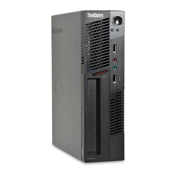
Figure 1. Front connector, control, and indicator locations Hard disk drive activity indicator USB connector (USB port 1) Power indicator Microphone connector Power switch Headphone connector Optical drive eject/close button USB connector (USB port 2) © Copyright Lenovo 2011, 2012... -
Page 76: Locating Connectors On The Rear Of Your Computer
Locating connectors on the rear of your computer Figure 2 “Rear connector locations” on page 70 shows the locations of the connectors on the rear of your computer. Some connectors on the rear of your computer are color-coded to help you determine where to connect the cables on your computer. -
Page 77: Locating Components
Locating components Figure 3 “Component locations” on page 71 shows the locations of the various components in your computer. To open the computer cover, see “Opening the computer cover” on page 72. Figure 3. Component locations Optical drive Microprocessor Front bezel Memory module Hard disk drive Battery... -
Page 78: Opening The Computer Cover
Do not open your computer or attempt any repair before reading and understanding the “Important safety information” in the ThinkCentre User Guide. To obtain a copy of the ThinkCentre User Guide, go to: http://www.lenovo.com/ThinkCentreUserGuides This section provides instructions on how to open the computer cover. -
Page 79: Removing And Reinstalling The Front Bezel
Do not open your computer or attempt any repair before reading and understanding the “Important safety information” in the ThinkCentre User Guide. To obtain a copy of the ThinkCentre User Guide, go to: http://www.lenovo.com/ThinkCentreUserGuides This section provides instructions on how to remove and reinstall the front bezel. -
Page 80: Installing Or Replacing A Memory Module
Do not open your computer or attempt any repair before reading and understanding the “Important safety information” in the ThinkCentre User Guide. To obtain a copy of the ThinkCentre User Guide, go to: http://www.lenovo.com/ThinkCentreUserGuides This section provides instructions on how to install or replace a memory module. -
Page 81: Installing Or Replacing The Pci Card
Do not open your computer or attempt any repair before reading and understanding the “Important safety information” in the ThinkCentre User Guide. To obtain a copy of the ThinkCentre User Guide, go to: http://www.lenovo.com/ThinkCentreUserGuides This section provides instructions on how to replace a PCI card. - Page 82 1. Remove all media from the drives and turn off all attached devices and the computer. Then, disconnect all power cords from electrical outlets and disconnect all cables that are connected to the computer. 2. Open the computer cover. See “Opening the computer cover” on page 72. 3.
-
Page 83: Replacing The Hard Disk Drive
Do not open your computer or attempt any repair before reading and understanding the “Important safety information” in the ThinkCentre User Guide. To obtain a copy of the ThinkCentre User Guide, go to: http://www.lenovo.com/ThinkCentreUserGuides This section provides instructions on how to replace the hard disk drive. -
Page 84: Replacing The Optical Drive
Do not open your computer or attempt any repair before reading and understanding the “Important safety information” in the ThinkCentre User Guide. To obtain a copy of the ThinkCentre User Guide, go to: http://www.lenovo.com/ThinkCentreUserGuides This section provides instructions on how to replace the optical drive. - Page 85 5. Press the blue release button and slide the optical drive out the front of the computer. Figure 13. Removing the optical drive 6. Install the optical drive retainer on the side of the new optical drive. Figure 14. Installing the retainer on the optical drive 7.
-
Page 86: Replacing The Battery
Do not open your computer or attempt any repair before reading and understanding the “Important safety information” in the ThinkCentre User Guide. To obtain a copy of the ThinkCentre User Guide, go to: http://www.lenovo.com/ThinkCentreUserGuides Your computer has a special type of memory that maintains the date, time, and settings for built-in features, such as parallel-port assignments (configuration). -
Page 87: Replacing The Heat Sink
Do not open your computer or attempt any repair before reading and understanding the “Important safety information” in the ThinkCentre User Guide. To obtain a copy of the ThinkCentre User Guide, go to: http://www.lenovo.com/ThinkCentreUserGuides This section provides instructions on how to replace the heat sink. - Page 88 4. Follow this sequence to remove the four screws that secure the heat sink to the system board: a. Partially remove screw , then fully remove screw , and then fully remove screw b. Partially remove screw , then fully remove screw , and then fully remove screw Note: Carefully remove the four screws from the system board to avoid any possible damage to the system board.
-
Page 89: Replacing The Microprocessor
Do not open your computer or attempt any repair before reading and understanding the “Important safety information” in the ThinkCentre User Guide. To obtain a copy of the ThinkCentre User Guide, go to: http://www.lenovo.com/ThinkCentreUserGuides This section provides instructions on how to replace the microprocessor. - Page 90 7. Lift the small handle and open the retainer to access the microprocessor Figure 20. Accessing the microprocessor 8. Lift the microprocessor straight up and out of the microprocessor socket. Figure 21. Removing the microprocessor Notes: a. Your microprocessor and socket might look different from the one illustrated. ThinkCentre Hardware Maintenance Manual...
- Page 91 b. Note the orientation of the microprocessor in the socket. You can either look for the small triangle on one corner of the microprocessor or note the orientation of the notches on the microprocessor. This is important when installing the new microprocessor on the system board. c.
-
Page 92: Replacing The System Board
Do not open your computer or attempt any repair before reading and understanding the “Important safety information” in the ThinkCentre User Guide. To obtain a copy of the ThinkCentre User Guide, go to: http://www.lenovo.com/ThinkCentreUserGuides This section provides instructions on how to replace the system board. - Page 93 10. Lift the failing system board off the cover. 11. Position the new system board so that the screw holes are aligned with the mounting studs on the cover. 12. Install the screws to secure the new system board to the protective cover. 13.
-
Page 94: Replacing The System Fan Assembly
Do not open your computer or attempt any repair before reading and understanding the “Important safety information” in the ThinkCentre User Guide. To obtain a copy of the ThinkCentre User Guide, go to: http://www.lenovo.com/ThinkCentreUserGuides This section provides instructions on how to replace the system fan assembly. - Page 95 To replace the system fan assembly, do the following: 1. Remove all media from the drives and turn off all attached devices and the computer. Then, disconnect all power cords from electrical outlets and disconnect all cables that are connected to the computer. 2.
- Page 96 7. Pull and lift the system fan assembly out of the chassis. Figure 26. Removing the system fan assembly 8. When installing your new system fan assembly, use the new rubber mounts that come with the new system fan. 9. Install the two short rubber mounts in the new system fan assembly as shown. 10.
-
Page 97: Replacing The Internal Speaker
Do not open your computer or attempt any repair before reading and understanding the “Important safety information” in the ThinkCentre User Guide. To obtain a copy of the ThinkCentre User Guide, go to: http://www.lenovo.com/ThinkCentreUserGuides This section provides instructions on how to replace the internal speaker. -
Page 98: Replacing The Front Audio And Usb Assembly
Do not open your computer or attempt any repair before reading and understanding the “Important safety information” in the ThinkCentre User Guide. To obtain a copy of the ThinkCentre User Guide, go to: http://www.lenovo.com/ThinkCentreUserGuides This section provides instructions on how to replace the front audio and USB assembly. - Page 99 5. Remove the screw that secures the front audio and USB assembly bracket to the chassis. Figure 29. Removing the screw that secures the front audio and USB assembly to the chassis 6. Locate the power switch assembly beside the front audio and USB assembly. Remove the power switch assembly by releasing tab and tab that secure the power switch assembly to the chassis.
-
Page 100: Replacing The Ac Power Adapter
Do not open your computer or attempt any repair before reading and understanding the “Important safety information” in the ThinkCentre User Guide. To obtain a copy of the ThinkCentre User Guide, go to: http://www.lenovo.com/ThinkCentreUserGuides This section provides instructions on how to replace the ac power adapter. -
Page 101: Replacing The Ac Power Adapter Bracket
Do not open your computer or attempt any repair before reading and understanding the “Important safety information” in the ThinkCentre User Guide. To obtain a copy of the ThinkCentre User Guide, go to: http://www.lenovo.com/ThinkCentreUserGuides This section provides instructions on how to replace the ac power adapter bracket. - Page 102 4. Press the metal clip as shown and then lift the power adapter bracket up to remove it from the chassis. Figure 33. Removing the ac power adapter bracket 5. Slide the ac power adapter out of the bracket. ThinkCentre Hardware Maintenance Manual...
- Page 103 6. Install the ac power adapter into the new power adapter bracket as shown. Figure 34. Installing the ac power adapter into the new bracket 7. Insert the two tabs and the tab on the new power adapter bracket into the corresponding holes in the chassis, and then press the new bracket downward to secure the bracket to the chassis.
-
Page 104: Completing The Parts Replacement
Completing the parts replacement After completing the installation or replacement for all parts, you need to close the computer cover and reconnect cables. Depending on the parts you installed or replaced, you might need to confirm the updated information in the Setup Utility program. Refer to Chapter 6 “Using the Setup Utility program” on page 41. To close the computer cover and reconnect cables to your computer, do the following: 1. -
Page 105: Chapter 9. Fru Lists
Optional-service CRU. Overall MT: 0266, 0384, 2491, 4168, 5027, 5067, , and 7519 The following replaceable components are available for the 0266, 0384, 2491, 4168, 5027, 5067, , and 7519 machine type models. © Copyright Lenovo 2011, 2012... - Page 106 Item # FRUs FRU # Optical drive, DVD-ROM drive - 16x/48x - SATA • MT 0266: A1H A1V A3A A3T C2J C4J C6J A5G A6G B3G D4J D6J E7J E9J • MT 0384: A1G A2G • MT 2491: 71Y5543 • MT 4168: •...
- Page 107 Item # FRUs FRU # Hard disk drive, SATA 250GB 7200RPM/3Gb/8M • MT 0266: A3A A3T A5G A6G A7G A8G E1Q E2Q E7J E8J E9J F1J • MT 0384: A9G A1G A2G A3G • MT 2491: 40Y9036 • MT 4168: •...
- Page 108 Item # FRUs FRU # Hard disk drive, SATA 500GB 7200RPM/3Gb/16M • MT 0266: B8U B8F B8S B8M A1H A1V A2H A2V B4S B4D B4Y B5S B5D B5Y C9G A9G B1G B2G B3G D1U D1F D1S D2G D3U D3F D3S D9G E2Q E3Q E4Q E6J •...
- Page 109 Item # FRUs FRU # Hard disk drive, SATAIII 320GB 7200RPM/6Gb/16M • MT 0266: B6M B7U B7F B7S B7M A4A A4T C8G C2J C3J C4J C5J C6J C7J B9G C1G D4J D5J D6J D7J D8J • MT 0384: • MT 2491: A1G A2G 03T7040 •...
- Page 110 Item # FRUs FRU # Hard disk drive, 2.5 inch 300G 10K RPM hard disk drive • MT 0266: • MT 0384: • MT 2491: 91Y1657 • MT 4168: • MT 5067: • MT 7516: • MT 7519: Power supply, 150W power adapter •...
- Page 111 Item # FRUs FRU # Microprocessor, Ci3 2100 SANDY BRIDGE stepping Q0 3MB 2c FCLGA 3.1GHZ 65W • MT 0266: • MT 0384: • MT 2491: • MT 4168: 03T8011 • MT 5067: • MT 7516: B5M B6M A1H A1V A2H A2V A3A A3T A4A A4T B4S B4D B4Y B8J B9J C1J C2J B7G A5G A6G A7G A8G A9G B1G B2G B3G C5U C5F C5S C3J C4J C6J C7J C8J C9J D5Q D6Q D7Q D8Q...
- Page 112 Item # FRUs FRU # Microprocessor, Ci5 2400S SANDY BRIDGE stepping D2 6MB 4c FCLGA 2.5GHZ 65W vPro • MT 0266: B6M B7U B7F B7S B7M B8U B8F B8S B8M A1H A1V A2H A2V A3A A3T A4A A4T B4S B4D B4Y B5S B5D B5Y C8G C9G C2J C3J C4J C5J C6J C7J B9G C1G A5G A6G A7G A8G A9G B1G B2G B3G D1U D1F D1S D2G D7J D8J D9G E6J E7J E8J...
- Page 113 Item # FRUs FRU # Microprocessor, Core i3-2125 SANDY BRIDGE, 3MB J-1 2C/4T 3.30 GHz, 65W • MT 0266: • MT 0384: • MT 2491: 03T8357 • MT 4168: • MT 5067: • MT 7516: • MT 7519: Microprocessor, Core i3-2130 SANDY BRIDGE, 3MB Q-0 2C/4T 3.40 GHz, 65W •...
- Page 114 Item # FRUs FRU # Microprocessor, G540 SANDY BRIDGE 2MB Q-0 2c FCLGA 2.5GHz 65W • MT 0266: • MT 0384: • MT 2491: 03T8354 • MT 4168: • MT 5067: • MT 7516: • MT 7519: Microprocessor, G530 SANDY BRIDGE 2MB Q-0 2c FCLGA 2.5GHz 65W •...
- Page 115 Item # FRUs FRU # Memory module, 2GB PC3-10600 1333MHz DDR3 SoDIMM • MT 0266: A1H A1V A2H A2V A3A A3T A4A A4T B4S B4D B4Y B5S B5D B5Y C8G C9G C2J C3J C4J C5J B9G C1G A5G A6G A7G A8G A9G B1G B2G B3G D2G D6J D7J D8J E1Q E5Q E6J E7J E8J •...
- Page 116 Item # FRUs FRU # • MT 7519: A1A A1T A2G A3G A7V A8V A9G B1G B2A B2T B3U B3F B3SMT 7519: A1A A1T A2G A3G A7V A8V A9G B1G B2A B2T B3U B3F B3S System board, Intel Q67 planar - without LAN surge planar-special bid-Russia only •...
-
Page 117: Mechanical Frus
Mechanical FRUs Mechanical FRU # Fru, 4.8L Intel 65W thermal kit • MT 0266: all modles • MT 0384: all modles • MT 2491: all modles 03T7055 • MT 4168: all modles • MT 5067: all modles • MT 7516: all modles •... - Page 118 Mechanical FRU # Fru, second serial port cable 250mm (with level shift IC) • MT 0266: all modles • MT 0384: all modles • MT 2491: all modles 71Y6217 • MT 4168: all modles • MT 5067: all modles • MT 7516: all modles •...
- Page 119 Mechanical FRU # Fru, optical disk driver blank bezel, plastic, without optical disk driver • MT 0266: all modles • MT 0384: all modles • MT 2491: all modles 45K6212 • MT 4168: all modles • MT 5067: all modles •...
- Page 120 Mechanical FRU # Fru, blank cover without media card reader • MT 0266: all modles • MT 0384: all modles • MT 2491: all modles 45K6214 • MT 4168: all modles • MT 5067: all modles • MT 7516: all modles •...
- Page 121 Mechanical FRU # Fru, access cover assembly • MT 0266: all modles • MT 0384: all modles • MT 2491: all modles 45K6215 • MT 4168: all modles • MT 5067: all modles • MT 7516: all modles • MT 7519: all modles Fru, base cover assembly •...
-
Page 122: Keyboard And Mouse
Mechanical FRU # Fru, C2 switch assembly • MT 0266: all modles • MT 0384: all modles • MT 2491: all modles 45K6415 • MT 4168: all modles • MT 5067: all modles • MT 7516: all modles • MT 7519: all modles Fru, front I/O cable assembly •... - Page 123 Keyboard - Preferred Pro USB Keyboard FRU # • MT 0266: • MT 0384: • MT 2491: 41A5291 • MT 4168: • MT 5067: • MT 7516: • MT 7519: • MT 0266: C8G C9G B9G C1G A5G A6G A7G A8G A9G B1G B2G B3G D2G •...
- Page 124 Keyboard - Preferred Pro USB Keyboard FRU # Bulgarian • MT 0266: C8G C9G B9G C1G A5G A6G A7G A8G A9G B1G B2G B3G D2G • MT 0384: A9G A7G A8G A1G A2G A3G A4G A5G A6G • MT 2491: A1G A2G A3G A4G 41A5295 •...
- Page 125 Keyboard - Preferred Pro USB Keyboard FRU # Dutch • MT 0266: C8G C9G B9G C1G A5G A6G A7G A8G A9G B1G B2G B3G D2G • MT 0384: A9G A7G A8G A1G A2G A3G A4G A5G A6G • MT 2491: A1G A2G A3G A4G 41A5299 •...
- Page 126 Keyboard - Preferred Pro USB Keyboard FRU # German • MT 0266: C8G C9G B9G C1G A5G A6G A7G A8G A9G B1G B2G B3G D2G • MT 0384: A9G A7G A8G A1G A2G A3G A4G A5G A6G • MT 2491: A1G A2G A3G A4G 41A5303 •...
- Page 127 Keyboard - Preferred Pro USB Keyboard FRU # Hungarian • MT 0266: C8G C9G B9G C1G A5G A6G A7G A8G A9G B1G B2G B3G D2G • MT 0384: A9G A7G A8G A1G A2G A3G A4G A5G A6G • MT 2491: A1G A2G A3G A4G 41A5307 •...
- Page 128 Keyboard - Preferred Pro USB Keyboard FRU # LA Spanish • MT 0266: B7S B8S B4S B4D B4Y B5S B5D B5Y D1S D3S • MT 0384: • MT 2491: 41A5312 • MT 4168: • MT 5067: A2S A2D A2Y A1S A1D A1Y A3S A3D A3Y •...
- Page 129 Keyboard - Preferred Pro USB Keyboard FRU # Romanian • MT 0266: C8G C9G B9G C1G A5G A6G A7G A8G A9G B1G B2G B3G D2G • MT 0384: A9G A7G A8G A1G A2G A3G A4G A5G A6G • MT 2491: A1G A2G A3G A4G 41A5317 •...
- Page 130 Keyboard - Preferred Pro USB Keyboard FRU # Slovak • MT 0266: C8G C9G B9G C1G A5G A6G A7G A8G A9G B1G B2G B3G D2G • MT 0384: A9G A7G A8G A1G A2G A3G A4G A5G A6G • MT 2491: A1G A2G A3G A4G 41A5320 •...
- Page 131 Keyboard - Preferred Pro USB Keyboard FRU # Thailand • MT 0266: A3T A4T • MT 0384: • MT 2491: 41A5324 • MT 4168: • MT 5067: A1T A3T • MT 7516: A3T A4T D3T D4T • MT 7519: A1T B2T Turkish •...
- Page 132 Keyboard - Preferred Pro USB Keyboard FRU # US European • MT 0266: C8G C9G B9G C1G A5G A6G A7G A8G A9G B1G B2G B3G D2G • MT 0384: A9G A7G A8G A1G A2G A3G A4G A5G A6G • MT 2491: A1G A2G A3G A4G 41A5328 •...
- Page 133 Keyboard - Preferred Pro USB Keyboard FRU # • MT 7519: Keyboard - Preferred Pro Full Size PS/2 FRU # PS/2--US English • MT 0266: • MT 0384: • MT 2491: 41A5039 • MT 4168: • MT 5067: • MT 7516: •...
- Page 134 Keyboard - Preferred Pro Full Size PS/2 FRU # PS/2--Belgium English • MT 0266: • MT 0384: • MT 2491: 41A5043 • MT 4168: • MT 5067: • MT 7516: • MT 7519: PS/2--Brazilian Portuguese • MT 0266: • MT 0384: •...
- Page 135 Keyboard - Preferred Pro Full Size PS/2 FRU # PS/2--Danish • MT 0266: • MT 0384: • MT 2491: 41A5048 • MT 4168: • MT 5067: • MT 7516: • MT 7519: PS/2--Dutch • MT 0266: • MT 0384: • MT 2491: 41A5049 •...
- Page 136 Keyboard - Preferred Pro Full Size PS/2 FRU # PS/2--German • MT 0266: • MT 0384: • MT 2491: 41A5053 • MT 4168: • MT 5067: • MT 7516: • MT 7519: PS/2--Greek • MT 0266: • MT 0384: • MT 2491: 41A5054 •...
- Page 137 Keyboard - Preferred Pro Full Size PS/2 FRU # PS/2--Iceland • MT 0266: • MT 0384: • MT 2491: 41A5057 • MT 4168: • MT 5067: • MT 7516: • MT 7519: PS/2--Italian • MT 0266: • MT 0384: • MT 2491: 41A5058 •...
- Page 138 Keyboard - Preferred Pro Full Size PS/2 FRU # PS/2--Norwegian • MT 0266: • MT 0384: • MT 2491: 41A5062 • MT 4168: • MT 5067: • MT 7516: • MT 7519: PS/2--Polish • MT 0266: • MT 0384: • MT 2491: 41A5063 •...
- Page 139 Keyboard - Preferred Pro Full Size PS/2 FRU # PS/2--Serbian/Cyrillic • MT 0266: • MT 0384: • MT 2491: 41A5067 • MT 4168: • MT 5067: • MT 7516: • MT 7519: PS/2--Slovak • MT 0266: • MT 0384: • MT 2491: 41A5068 •...
- Page 140 Keyboard - Preferred Pro Full Size PS/2 FRU # PS/2--Thailand • MT 0266: • MT 0384: • MT 2491: 41A5072 • MT 4168: • MT 5067: • MT 7516: • MT 7519: PS/2--Turkish • MT 0266: • MT 0384: • MT 2491: 41A5073 •...
- Page 141 Keyboard - Preferred Pro Full Size PS/2 FRU # PS/2--Slovenian • MT 0266: • MT 0384: • MT 2491: 41A5077 • MT 4168: • MT 5067: • MT 7516: • MT 7519: PS/2--Indian • MT 0266: • MT 0384: • MT 2491: 54Y8382 •...
- Page 142 Keyboard - Fingerprint FRU # Belgium French • MT 0266: • MT 0384: • MT 2491: 57Y4783 • MT 4168: • MT 5067: • MT 7516: • MT 7519: Belgium English • MT 0266: • MT 0384: • MT 2491: 57Y4784 •...
- Page 143 Keyboard - Fingerprint FRU # Czech (ABB) • MT 0266: • MT 0384: • MT 2491: 57Y4788 • MT 4168: • MT 5067: • MT 7516: • MT 7519: Danish • MT 0266: • MT 0384: • MT 2491: 57Y4789 •...
- Page 144 Keyboard - Fingerprint FRU # French Canadian • MT 0266: • MT 0384: • MT 2491: 57Y4793 • MT 4168: • MT 5067: • MT 7516: • MT 7519: German • MT 0266: • MT 0384: • MT 2491: 57Y4794 •...
- Page 145 Keyboard - Fingerprint FRU # Hungarian • MT 0266: • MT 0384: • MT 2491: 57Y4798 • MT 4168: • MT 5067: • MT 7516: • MT 7519: Iceland • MT 0266: • MT 0384: • MT 2491: 57Y4799 • MT 4168: •...
- Page 146 Keyboard - Fingerprint FRU # LA Spanish • MT 0266: • MT 0384: • MT 2491: 57Y4803 • MT 4168: • MT 5067: • MT 7516: • MT 7519: Norwegian • MT 0266: • MT 0384: • MT 2491: 57Y4804 •...
- Page 147 Keyboard - Fingerprint FRU # Romanian • MT 0266: • MT 0384: • MT 2491: 57Y4808 • MT 4168: • MT 5067: • MT 7516: • MT 7519: Russian/Cyrillic • MT 0266: • MT 0384: • MT 2491: 57Y4809 • MT 4168: •...
- Page 148 Keyboard - Fingerprint FRU # Swedish/Finnish • MT 0266: • MT 0384: • MT 2491: 57Y4813 • MT 4168: • MT 5067: • MT 7516: • MT 7519: Swiss French/German • MT 0266: • MT 0384: • MT 2491: 57Y4814 •...
- Page 149 Keyboard - Fingerprint FRU # UK English • MT 0266: • MT 0384: • MT 2491: 57Y4818 • MT 4168: • MT 5067: • MT 7516: • MT 7519: US European • MT 0266: • MT 0384: • MT 2491: 57Y4819 •...
- Page 150 Keyboard - Fingerprint FRU # • MT 0266: • MT 0384: • MT 2491: 03X8003 • MT 4168: • MT 5067: • MT 7516: • MT 7519: Belgium French • MT 0266: • MT 0384: • MT 2491: 03X8004 • MT 4168: •...
- Page 151 Keyboard - Fingerprint FRU # Chinese/US • MT 0266: • MT 0384: • MT 2491: 03X8008 • MT 4168: • MT 5067: • MT 7516: • MT 7519: Czech (ABB) • MT 0266: • MT 0384: • MT 2491: 03X8009 •...
- Page 152 Keyboard - Fingerprint FRU # French Canadian • MT 0266: • MT 0384: • MT 2491: 03X8013 • MT 4168: • MT 5067: • MT 7516: • MT 7519: French Canadian • MT 0266: • MT 0384: • MT 2491: 03X8014 •...
- Page 153 Keyboard - Fingerprint FRU # Hebrew • MT 0266: • MT 0384: • MT 2491: 03X8018 • MT 4168: • MT 5067: • MT 7516: • MT 7519: Hungarian • MT 0266: • MT 0384: • MT 2491: 03X8019 • MT 4168: •...
- Page 154 Keyboard - Fingerprint FRU # Korean • MT 0266: • MT 0384: • MT 2491: 03X8023 • MT 4168: • MT 5067: • MT 7516: • MT 7519: LA Spanish • MT 0266: • MT 0384: • MT 2491: 03X8024 •...
- Page 155 Keyboard - Fingerprint FRU # Romanian • MT 0266: • MT 0384: • MT 2491: 03X8038 • MT 4168: • MT 5067: • MT 7516: • MT 7519: Romanian • MT 0266: • MT 0384: • MT 2491: 03X8039 • MT 4168: •...
- Page 156 Keyboard - Fingerprint FRU # Spanish • MT 0266: • MT 0384: • MT 2491: 03X8030 • MT 4168: • MT 5067: • MT 7516: • MT 7519: Swedish/Finnish • MT 0266: • MT 0384: • MT 2491: 03X8031 • MT 4168: •...
- Page 157 03X8037 • MT 4168: • MT 5067: • MT 7516: • MT 7519: Mice FRU # Lenovo enhanced optical USB mouse • MT 0266: • MT 0384: 45J4889 • MT 2491: • MT 4168: • MT 5067: • MT 7516:...
-
Page 158: Adapters And Miscellaneous Frus
Mice FRU # • MT 7519: Optical wheel mouse PS/2 • MT 0266: B6M B7U B7F B7S B7M B8U B8F B8S B8M A1H A1V A2H A2V A3A A3T A4A A4T B4S B4D B4Y B5S B5D B5Y C8G C9G C2J C3J C4J C5J C6J C7J B9G C1G A5G A6G A7G A8G A9G B1G B2G B3G D1U D1F D1S D2G D3U D3F D3S D4J D5J D6J D7J D8J D9G E1Q E2Q E3Q E4Q E5Q E6J E7J E8J E9J F1J... - Page 159 Adapters and miscellaneous FRU # Lenovo branded speakers • MT 0266: • MT 0384: • MT 2491: 41A5334 • MT 4168: • MT 5067: • MT 7516: • MT 7519: Speaker power brick • MT 0266: • MT 0384: • MT 2491: 89P8571 •...
-
Page 160: Power Cords
Power Cords Power Cords-primary FRU # Line Cord - US • MT 0266: B7U B7F B7S B8U B8F B8S A3A A3T A4A A4T B4S B4D B5S B5D D1U D1F D1S D3U D3F D3S • MT 0384: • MT 2491: 42T5004 •... - Page 161 Power Cords-primary FRU # Line Cord - Korea • MT 0266: • MT 0384: • MT 2491: 42T5077 • MT 4168: • MT 5067: A1K A1R A3R A3K • MT 7516: • MT 7519: Line Cord - Singapore, Malaysia, Brunei, Hong Kong •...
- Page 162 Power Cords-primary FRU # Line Cord - India • MT 0266: E1Q E2Q E3Q E4Q E5Q • MT 0384: • MT 2491: 42T5083 • MT 4168: • MT 5067: A1Q A3Q • MT 7516: D5Q D6Q D7Q D8Q • MT 7519: Line Cord - China •...
- Page 163 Power Cords-primary FRU # Line Cord - Denmark • MT 0266: C8G C9G B9G C1G A5G A6G A7G A8G A9G B1G B2G B3G D2G • MT 0384: A9G A7G A8G A1G A2G A3G A4G A5G A6G • MT 2491: A1G A2G A3G A4G 42T5041 •...
- Page 164 Power Cords-primary FRU # Line Cord - Thailand • MT 0266: • MT 0384: • MT 2491: 42T5004 • MT 4168: • MT 5067: A1T A3T • MT 7516: • MT 7519: A1T B2T Line Cord - UK, Ireland • MT 0266: C8G C9G B9G C1G A5G A6G A7G A8G A9G B1G B2G B3G D2G •...
- Page 165 Power Cords-secondary FRU # Line Cord - Brazil (Portuguese) • MT 0266: • MT 0384: • MT 2491: 42T5177 • MT 4168: • MT 5067: A2P A1P A3P • MT 7516: • MT 7519: Line Cord - LA High Volt (APU) •...
- Page 166 Power Cords-secondary FRU # Line Cord - India • MT 0266: E1Q E2Q E3Q E4Q E5Q • MT 0384: • MT 2491: 42T5168 • MT 4168: • MT 5067: A1G A1M A1A A3G A3M A3A • MT 7516: D5Q D6Q D7Q D8Q •...
- Page 167 Power Cords-secondary FRU # Line Cord - Italy • MT 0266: B4S B4Y B5S B5Y D1S D3S C8G C9G B9G C1G A5G A6G A7G A8G A9G B1G B2G B3G D2G D9G • MT 0384: • MT 2491: A1G A2G A3G A4G 42T5132 •...
-
Page 168: Recovery Discs
Power Cords-secondary FRU # Line Cord - Austria, Belgium, Croatia, Czechoslovakia, Finland, France, Germany, Hungary, Netherlands, Norway, Poland, Portugal, Romania, Spain, Sweden • MT 0266: C8G C9G B9G C1G A5G A6G A7G A8G A9G B1G B2G B3G D2G D9G • MT 0384: A9G A7G A8G A1G A2G A3G A4G A5G A6G 42T5114 •... - Page 169 Windows 7 Professional 32 FRU # Simplified Chinese • MT 0266: • MT 0384: • MT 2491: 03T0858 • MT 4168: • MT 5067: • MT 7516: • MT 7519: Chinese-Traditional • MT 0266: A1V A2V • MT 0384: • MT 2491: 03T0859 •...
- Page 170 Windows 7 Professional 32 FRU # Greek • MT 0266: B9G C1G • MT 0384: A7G A8G • MT 2491: 03T0863 • MT 4168: • MT 5067: A1G • MT 7516: B7G • MT 7519: German • MT 0266: B9G C1G •...
- Page 171 Windows 7 Professional 32 FRU # Italian • MT 0266: B9G C1G • MT 0384: A7G A8G • MT 2491: 03T0868 • MT 4168: • MT 5067: A1G • MT 7516: B7G • MT 7519: Japanese • MT 0266: C2J C3J C4J C5J D6J D7J D8J E6J E7J E8J •...
- Page 172 Windows 7 Professional 32 FRU # Romanian • MT 0266: B9G C1G • MT 0384: A7G A8G • MT 2491: 03T0873 • MT 4168: • MT 5067: A1G • MT 7516: B7G • MT 7519: Russian • MT 0266: B9G C1G •...
- Page 173 Windows 7 Professional 32 FRU # Turkish • MT 0266: B9G C1G • MT 0384: A7G A8G • MT 2491: 03T0878 • MT 4168: • MT 5067: A1G • MT 7516: B7G • MT 7519: English • MT 0266: A1H A2H A3A A4A E1Q E5Q •...
-
Page 174: Windows 7 Home Basic 32 Recovery Cd
Windows 7 Home Basic 32 Recovery CD Windows 7 Home Basic 32 FRU # Arabic • MT 0266: • MT 0384: • MT 2491: 03T0883 • MT 4168: • MT 5067: • MT 7516: • MT 7519: Brazilian Portuguese • MT 0266: •... -
Page 175: Windows 7 Home Premium 64 Recovery Cd
Windows 7 Home Basic 32 FRU # Spanish • MT 0266: • MT 0384: • MT 2491: 03T0888 • MT 4168: • MT 5067: • MT 7516: • MT 7519: Serbian-Latin • MT 0266: • MT 0384: • MT 2491: 03T0889 •... - Page 176 Windows 7 Home Premium 64 FRU # • MT 7519: Chinese-Simplified • MT 0266: • MT 0384: • MT 2491: 03T0920 • MT 4168: • MT 5067: • MT 7516: • MT 7519: Chinese-Traditional • MT 0266: • MT 0384: •...
- Page 177 Windows 7 Home Premium 64 FRU # Hong Kong • MT 0266: • MT 0384: • MT 2491: 03T0925 • MT 4168: • MT 5067: • MT 7516: • MT 7519: Italy • MT 0266: • MT 0384: • MT 2491: 03T0926 •...
-
Page 178: Windows 7 Home Premium 32 Recovery Cd
Windows 7 Home Premium 64 FRU # US English • MT 0266: • MT 0384: • MT 2491: 03T0930 • MT 4168: • MT 5067: • MT 7516: • MT 7519: C and L Nordics (DK/FI/SV/NO/EN) • MT 0266: • MT 0384: •... -
Page 179: Windows Xp Professional 32 Recovery Cd
Windows 7 Home Premium 32 FRU # • MT 7519: Windows XP Professional 32 Recovery CD Note: The Windows XP Professional recovery DVDs are available only for models with a valid Microsoft Windows XP Professional certificate of authenticity (COA) affixed to the system. Due to a Microsoft licensing limitation, if a model came with Windows XP Professional preinstalled from the factory, but has either a Windows 7 or Windows Vista COA affixed to the system, that model is eligible only for recovery DVDs that match the operating system specified on the COA. - Page 180 Windows XP Professional 32 FRU # Czech • MT 0266: • MT 0384: • MT 2491: 03T0725 • MT 4168: • MT 5067: • MT 7516: • MT 7519: Denmark • MT 0266: • MT 0384: • MT 2491: 03T0726 •...
- Page 181 Windows XP Professional 32 FRU # Hong Kong • MT 0266: • MT 0384: • MT 2491: 03T0729 • MT 4168: • MT 5067: • MT 7516: • MT 7519: Italian • MT 0266: • MT 0384: • MT 2491: 03T0730 •...
-
Page 182: Windows 7 Professional 64 Recovery Cd
Windows XP Professional 32 FRU # Spanish • MT 0266: • MT 0384: • MT 2491: 03T0734 • MT 4168: • MT 5067: • MT 7516: • MT 7519: Swedish • MT 0266: • MT 0384: • MT 2491: 03T0735 •... - Page 183 Windows 7 Professional 64 FRU # • MT 7519: Chinese-Simplified • MT 0266: • MT 0384: • MT 2491: 03T0896 • MT 4168: • MT 5067: A3C • MT 7516: • MT 7519: Chinese-Traditional • MT 0266: • MT 0384: •...
- Page 184 Windows 7 Professional 64 FRU # Greek • MT 0266: D2G D9G • MT 0384: • MT 2491: A1G A2G A3G A4G 03T0901 • MT 4168: • MT 5067: A3G • MT 7516: • MT 7519: A2G A3G A9G B1G German •...
- Page 185 Windows 7 Professional 64 FRU # Italy • MT 0266: D2G D9G • MT 0384: • MT 2491: A1G A2G A3G A4G 03T0906 • MT 4168: • MT 5067: A3G • MT 7516: • MT 7519: A2G A3G A9G B1G Japanese •...
- Page 186 Windows 7 Professional 64 FRU # Slovakian • MT 0266: D2G D9G • MT 0384: • MT 2491: A1G A2G A3G A4G 03T0911 • MT 4168: • MT 5067: A3G • MT 7516: • MT 7519: A2G A3G A9G B1G Spanish •...
-
Page 187: Windows Xp Professional Generic Recovery Cd
Windows 7 Professional 64 FRU # C and L Nordics (DK/FI/SV/NO/EN) • MT 0266: D2G D9G • MT 0384: • MT 2491: A1G A2G A3G A4G 03T0916 • MT 4168: • MT 5067: A3G • MT 7516: • MT 7519: A2G A3G A9G B1G C and L EMEA (NL/FR/GR/IT/EN) •... -
Page 188: Windows Vista Business 32 Recovery Cd
Windows XP Professional Generic FRU # • MT 7519: Hungary • MT 0266: • MT 0384: • MT 2491: 03W7486 • MT 4168: • MT 5067: • MT 7516: • MT 7519: Korean • MT 0266: • MT 0384: • MT 2491: 03W7489 •... -
Page 189: Windows Vista Home Basic 32 Recovery Cd
Windows Vista Business 32 FRU # India English • MT 0266: • MT 0384: • MT 2491: 03T1311 • MT 4168: • MT 5067: • MT 7516: • MT 7519: US English • MT 0266: • MT 0384: • MT 2491: 03T1312 •... - Page 190 Windows Vista Home Basic 32 FRU # Japanese • MT 0266: • MT 0384: • MT 2491: 03T1315 • MT 4168: • MT 5067: • MT 7516: • MT 7519: Spanish • MT 0266: • MT 0384: • MT 2491: 03T1316 •...
-
Page 191: Chapter 10. Additional Service Information
“Using passwords” on page 41. Operating system password Note: This section applies only to computer models that have an operating system preinstalled from Lenovo. An operating system password is very similar to a power-on password and denies access to the computer by an unauthorized user when the password is activated. -
Page 192: Updating (Flashing) The Bios From A Disc
Updating (flashing) the BIOS from your operating system Note: Because Lenovo makes constant improvements to its Web sites, the Web page contents are subject to change without notice, including the contents referenced in the following procedure. -
Page 193: Recovering From A Post/Bios Update Failure
Recovering from a POST/BIOS update failure If the power to your computer is interrupted while the POST and BIOS is being updated, your computer might not restart correctly. If this happens, perform the following procedure to recover from the POST and BIOS update failure. - Page 194 ThinkCentre Hardware Maintenance Manual...
-
Page 195: Appendix A. Notices
Lenovo representative for information on the products and services currently available in your area. Any reference to a Lenovo product, program, or service is not intended to state or imply that only that Lenovo product, program, or service may be used. Any functionally equivalent product, program, or service that does not infringe any Lenovo intellectual property right may be used instead. -
Page 196: Television Output Notice
Macrovision Corporation. Reverse engineering or disassembly is prohibited. Trademarks The following terms are trademarks of Lenovo in the United States, other countries, or both: Lenovo PS/2 Rescue and Recovery... -
Page 197: Index
POST/BIOS update failure hard disk drive, replacing recovery heat sink, replacing boot-block replacing battery front fan assembly installing options hard disk drive memory module heat sink © Copyright Lenovo 2011, 2012... - Page 198 internal speaker microprocessor security enabling or disabling selecting startup device temporary startup device setting password settings changing viewing Setup Utility Setup Utility program, starting Setup Utility, exiting starting the Setup Utility program startup device sequence, changing temporary, selecting system board connectors locating parts memory module...
- Page 200 Part Number: 0A74394 Printed in (1P) P/N: 0A74394 *1P0A74394*...