
Related Manuals for Epson ELPMB27


Summary of Contents for Epson ELPMB27
- Page 1 ELPMB27 Short Throw Projector Wall Mount Installation Manual xxx(FR) xxx(DE) xxx(IT) xxx(ES) xxx(PT) xxx(ZHS)
-
Page 2: Safety Instructions
Safety Instructions Before using the wall mount, make sure you read all of the safety instructions below and then save this manual for later reference. Incomplete or incorrect installation could cause damage to the product or result in personal injury or property damage. - Page 3 In order to resist vibration and support the weight of the projector and optional accessories, use M8 nuts and bolts and tighten all screws firmly after installation. Otherwise, the projector or wall mount may fall and cause personal injury or property damage. Epson accepts no responsibility for any damage or injury caused by lack of wall strength or inadequate installation.
-
Page 4: Before Use
Direct sunlight and some kinds of fluorescent lights could interfere with the remote control of the projector. Epson recommends that the length of the connection cord be less than 20 meters (65.61 ft.) in order to reduce external noise. -
Page 5: Package Contents
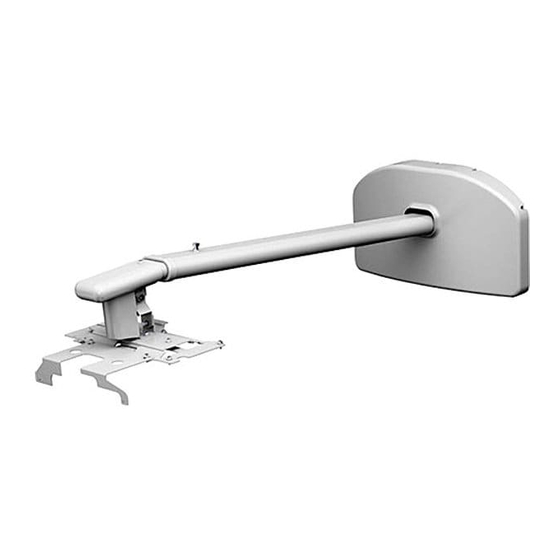
Package Contents Adjustment unit Arm unit Arm plate Attachment plate Wall plate Wall plate cover Arm cover Cable cover Interface cover bracket Hexagonal wrenches (M4 and M8) M4 x 12 mm hexagon socket head cap M4 x 12 mm hexagon socket head M4 x 12 mm hexagon socket head bolts cap bolts... -
Page 6: Specifications
Specifications Weight Approx. 10 kg (22 lbs.) Maximum load capacity 5.5 kg (12.13 lbs.) Arm length 1510 mm (15.45 inches) (from wall plate attachment point to arm cover point) Vertical slide adjustment range 0 to 134 mm (0 to 5.27 inches) (arm length minimum) 0 to 230 mm (0 to 9.05 inches) (arm length maximum) Vertical tilt adjustment range 0 to - 9.5°... -
Page 7: Screen Size And Projection Distance
Screen Size and Projection Distance Refer to the tables on the following pages and install the mount and projector to project images at the appropriate size. The values are only a guide. The recommended projection distance is 70 to 119 cm (27.55 to 46.85 inches). Center of lens Projected image... -
Page 12: Assembly And Installation
Use M8 nuts and bolts. Nuts and bolts smaller than M8 could cause the mount to fall. ❏ Epson accepts no responsibility for any damage or injury caused by lack of wall strength or inadequate installation. At the point where the wall mount is installed, make sure there is a gap of 410 to 660 mm (16 to 26 inches) from the top of the image projected onto the white board to the ceiling. - Page 13 Position the wall plate over the marks you made in step 1, and then mark the points where the wall plate will be secured as shown in the following illustration. Insert the anchors into at least three points. If you insert four anchors, use the four point As or four point Bs as shown below. For 3 points For 4 points Drill holes of the following diameters and depths at the points you marked.
- Page 14 2. Assembling the wall mount Attach the adjustment unit to the arm unit. Secure temporarily using the hexagonal wrenches (M4 and M8) and M4 x 12 mm hexagon socket head cap bolt and M8 x 15 mm hexagon socket head cap bolt. Arm unit M4 x 12 mm hexagon socket head cap bolt...
- Page 15 3. Routing the cables through the arm unit If you are installing ELPIU03 (sold separately), you also need to route the USB cable supplied with ELPIU03 through the arm unit. Arm unit USB cable for ELPIU03 Caution Problems may occur if you use this product without routing the cables through the arm unit. Route the USB cable that connects ELPIU03 to the computer so that the type B connector emerges on the adjustment unit side.
- Page 16 5. Attaching the attachment plate to the projector Place the projector upside down. Attach the attachment plate to the projector using the hexagonal wrench (M4) and five M4 x 12 mm bolts with washers/ spring washers. M4 x 12 mm hexagon socket head cap bolts (x5) with washers/spring washers Attachment plate...
-
Page 17: Connecting The Cables
7. Extending the arm, adjusting the length, and securing temporarily Loosen the screw on the arm.( Adjust the length of the arm using the measure on the bottom to match the projection distance recommended in "Screen Size and Projection Distance" on page 7.( After adjusting the length, secure the arm position temporarily by tightening the screw on top.( 8. - Page 18 10. Turning on the projector and checking the screen Plug in the projector. Turn on the projector. Loosen the screws on the adjustment unit (A, B, C, and D) as shown below to adjust the screen position. Adjust the vertical slide (arm angle) using screw (E) on the bottom of the arm plate. The arm rises when you tighten the screw, and lowers when you loosen it.
-
Page 19: Attaching The Cable Cover
11. Attaching the interface cover bracket Attach the interface cover bracket using the hexagonal wrench (M4) and two M4 x 12 mm bolts with washers. M4 x 12 mm hexagon socket head cap bolts (x2) with washers Interface cover bracket 12. - Page 20 ❏ Do not hang on the mount or hang heavy objects on it. If the mount or the projector falls, it could cause personal injury or property damage. Copyright © Seiko Epson Corporation 2011. All rights reserved. Printed in China.