Table of Contents
Advertisement
Available languages
Available languages
]CRRFTSMRN 1
Operator's Manual
Snow Thrower
7.75 Horsepower
Electric Start
26-inch
Dual Stage
Model 536.887752
CAUTION: Before using this product,
read this manual and follow all of its
Safety Rules and Operating Instructions.
Manual del usario
Quitanieves
de 26 pulgadas
7.75 caballos
de fuerza (hp)
Biet&pico
Arranque
el_ctrico
Modelo 536.887752
PRECAUCI6N:
Antes de usar este producto,
lea este manual y siga todas las reglas de
seguridad e instrucciones de operaci6n.
Sears, Roebuck
and Co., Hoffman
Estates,
IL 60179 U.S.A.
F-031027L
www.sears.com/craftsman
Advertisement
Table of Contents

Related Manuals for Craftsman 536.887752


Summary of Contents for Craftsman 536.887752
- Page 1 7.75 caballos de fuerza (hp) Biet&pico Arranque el_ctrico Modelo 536.887752 PRECAUCI6N: Antes de usar este producto, lea este manual y siga todas las reglas de seguridad e instrucciones de operaci6n. Sears, Roebuck and Co., Hoffman Estates, IL 60179 U.S.A. www.sears.com/craftsman F-031027L...
- Page 2 ON CRAFTSMAN SNOW THROWER For two years from the date of purchase, when this Craftsman Snow thrower is maintained, lubricated, and tuned up according to the operating and maintenance instructions in the owner's manual, Sears will repair, free of charge, any defect in material or workmanship.
- Page 3 TRAINING Always wear safety glasses or eye shields during operation or while performing an ad- Read this operating and service instruction justment or repair to protect eyes from manual carefully. Be thoroughly familiar foreign objects that may be thrown from the with the controls and the proper use of the snow thrower.
- Page 4 13.Never operate the snow t hrower near en- MAINTENANCE AND STORAGE closures, automobiles, window wells, drop- Check shear bolts and other bolts at fre- offs, and t_e like without proper adjustment quent intervals for proper tightness to be of Me snow discharge angle. Keep children sure the snow thrower is in safe working and pets away.
- Page 5 Drive Clutch Forward Reverse Auger Clutch Auger Collector Engage Push To Engage Fuel Fuel Oil Mixture Electric Starter Discharge DOWN Discharge UP Discharge LEFT Discharge RIGHT Weight Transfer Weight Transfer Transmission Ignition Key Lift Handle To Depress Pedal Insert To Run, Engage To Disengage Pull Out To Stop.
- Page 6 CONTENTS OF PARTS BAG (ACTUAL SIZE) 1 - Owner's Manual (not shown) 1 - Packet of Fuel Stabilizer (not shown) 1 - Warranty Card (not shown) Parts,foundin toolboxlocatedon beltcover *Non-Assembly (not actual size) ¢- 1 - Shift Lever Knob 1 - Washer 1 - Nut 1 - Igniti_ F-031027L...
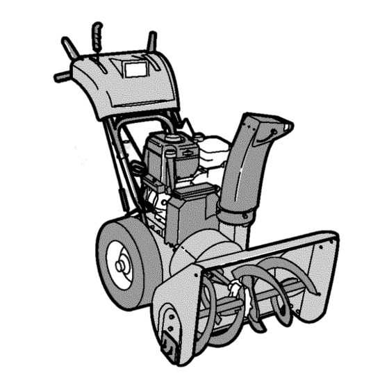
- Page 7 Figure 2 shows the snow thrower com- safety glasses or eye shields ARNING: Always wear pletely assembled. while assembling snow References to the right or left hand side thrower. of the snow thrower are from the view- point of the operator's position behind TOOLS REQUIRED the unit.
- Page 8 6. Install the fasteners that were re- TO ASSEMBLE THE HANDLE CRANK ASSEMBLY moved in step 4. DO NOT tighten until all bolts are in place. 1. Cut tie holding shift rod to lower handle and move shifter to the first forward gear.
- Page 9 NOTE: If the cables have become dis- Traction Drive Cable Auger Drive Cable connected, connect cables as shown in Figure 7. Figure 7 SNOW CHUTE ASSEMBLY 6. Turn crank assembly clockwise and make sure all carriage bolts are 1. Turn crank assembly counterclock- tight.
- Page 10 How To Install The Speed Control 1. Put the speed select lever into the sixth gear position. 2. Attach the speed control rod (end with 90 °bend) to the speed select Speed Select bracket with washer and cotter Lever pin. See Figure f0. Bracket 3.
- Page 11 How To Set The Length Of The Cables The cables were adjusted at the factory and no adjustments should be neces- sary. However, after the handles are put in the operating position, the cables can be too tight or too loose. If an adjust- ment is necessary, see "How To Check And Adjust The Cables"...
- Page 12 KNOW YOUR SNOW THROWER READ THIS OWNER'S MANUAL AND SAFETY RULES BEFORE OPERATING YOUR SNOW THROWER. Compare the illustrations with your SNOW THROWER to familiarize yourself with the location of various controls and adjustments. Save this manual for future reference. Traction Drive Lever Auger Drive Lever _, Gas Tank...
- Page 13 The operation ofanysnow thrower can result i nforeign o bjects b eing thrown intotheeyes, which canresult inse- vere eyedamage. Always w ear s afety glasses oreyeshields while operating thesnow thrower. Werecommend standard safety glasses orawide vision safety m ask for over y our g lasses.
- Page 14 TO USE WHEEL LOCKOUT PIN Klick Pin 1. The right hand wheel is secured to the axle with a klick pin. This unit was shipped with this klick pin in the Locked locked position (through wheel Position hole). See Figure 16. 2-Wheel Drive 2.
- Page 15 FILL GAS: The engine is certified to comply with Fuel Tank California and US EPA emission regula- tions for ULGE (Utility or Lawn and Gar- den Equipment) engines. ULGE engines are certified to operate on reg- ular unleaded gasoline. fuels (called gasohol or Figure 19 ARNING: Alcohol blended those using ethanol or...
- Page 16 HOW TO STOP THE ENGINE equipped with a three-wire 4_lk WARNING: The starter is 1. To stop the engine, move the power cord and plug and is throttle control lever to the "SLOW" designed to operate on 120 volt AC position, then move to the "STOP"...
- Page 17 Recoil Starter Handle gure 25 7. (ELECTRIC START) Connect the 4. Move throttle control to "FAST' power cord to the engine and de- position. Operate the engine with press the starter button. the throttle control in the "FAST" position (see Figure 23). Throttle Control Connect Power Cord /...
- Page 18 Tohelp prevent possible freeze-up of recoil starter andengine c ontrols, pro- gine indoors or in enclosed, d_lb WARNING: Never run en- ceed asfollows a fter e ach snow remov- poorly ventilated areas. En- aljob. gine exhaust contains CARBON 1. With theengine r unning, pull t he MONOXIDE, AN ODORLESS AND starter rope hard withacontinuous DEADLY GAS.
- Page 19 SERVICE R ECORDS Fillindates asyou Before Every Every Every complete r egular Each Each Before SERVICE service. Often Hours Hours Hours Season Stcrage DATES Lubricate Auger Shaft Check Engine Level Check Spark Plug AdjustDrive Belt * Adjust after 2 to 4 hours of use. GENERAL RECOMMENDATIONS AFTER EACH USE Run the machine to clear the auger...
- Page 20 PRODUCT SPECIFICATIONS Stand the snow blower up on the auger housing end. HORSEPOWER 7.75 HP NOTE: When the crank case if DISPLACEMENT 206 cc filled with oil, do not leave the snow blower standing up on the GASOLINE 4 quarts auger housing for an extended CAPACITY (unleaded)
- Page 21 ENGINE Change the oil every twenty-five (25) LUBRICATION hours or at least once a year if the Check the crankcase oil level before snow thrower is not used for twenty-five (25) hours. starting the engine and after each five (5) hours of continuous use. Add S.A.E. TO CHANGE ENGINE OIL 5W30 motor oil as needed.
- Page 22 raise the adjustable skids. Tighten the mounting nuts. See Figure 32. nect the spark plug wire and ARNING: Always discon- place it where it cannot NOTE: For rocky or uneven surfaces, make contact with spark plug to pre- raise the front of the snow thrower by vent accidental starting when mak- moving the skids down.
- Page 23 HOW TO REMOVE THE SNOW HOOD To access the spark plug, the snow hood must be removed as follows: 1. Remove the choke control knob (see Figure 33). 2. Remove the ON/OFF key. 3. Remove the four mounting screws. 4. Slowly remove the snow hood (see Figure 34).
- Page 24 BELT ADJUSTMENT 5. Have someone engage auger drive clutch. Check tension on belt (op- Traction Drive Belt posite idler pulley). Belt should de- flect about 1/2 inch (12.5 mm) with The traction drive belt has constant moderate pressure (Figure 38). You spring pressure and does not require may have to move idler pulley more an adjustment.
- Page 25 from the engine pulley. Replace Remove the bottom panel, the auger drive belt with an original Bolt Bottom Panel equipment replacement belt avail- able from a Sears service center. 8. Install the new auger drive belt onto the auger drive pulley and onto pulley.
- Page 26 How To Remove plate is properly secured (see The Traction Drive Belt Figure 41). If the snow thrower will not move for- ward, check the traction drive belt for wear or damage. If the traction drive belt is worn or damaged, replace the belt as follows.
- Page 27 BELT GUIDE ADJUSTMENT "Z" Fitting 1. Remove spark plug wire. 2. Have someone engage auger drive. 3. Measure the distance between the belt guide and belt. The distance should be 1/8 inch (3.175 mm) for guide. See Figure 42. Figure 43 _'/_--_ Belt Guide _'_'...
- Page 28 TRACTION DRIVE CABLE ADJUSTMENT 1. Runthe engine untilthe fuel tank is 6. Puehthe bottomof the traction empty and the engine stops. drive cable through the cable ad- 2. Stand the snow thrower up on the justment bracket until the "Z" hook can be removed.
- Page 29 HOW TO ADJUST OR REPLACE Turn the adaptor until the ball joint THE FRICTION WHEEL is aligned with the mounting hole in the shifter rod (see Figure 50). When aligned, attach the ball joint How To Check The Friction Wheel to the shifter rod.
- Page 30 How To Replace The Friction Wheel If the friction wheel is worn or damaged, the snow thrower will not move forward. The friction wheel must be replaced as follows. 1. Run the engine until the fuel tank is Wheel Bottom Panel empty and the engine stops.
- Page 31 11. Remove the three fasteners that 17. Check the adjustment of the friction hold the friction wheel to the hub wheel. See "How To Adjust The Friction Wheel" in this section. (see Figure 54). 18. Make sure the friction wheel and the 12.
- Page 32 HOW TO REPLACE 2. Disconnect the spark plug wire. Make sure all moving parts have THE AUGER SHEAR BOLT stopped. The augers are secured to the auger 3. Align the hole in the auger with the shaff with special shear bolts. These hole in the auger shaft.
- Page 33 If gasoline remains in the use fuel stabilizer supplied with unit tank, fumes may reach an open or purchase Craftsman Fuel Stabi- flame, spark or pilot light from a fur- lizer No. 3550. Add fuel stabilizer to nace, water heater, clothes dryer, any gasoline left in the tank to mini- cigarette, etc.
- Page 34 TROUBLE CAUSE CORRECTION Difficult starting Defective spark plug, Replace spark plug. Remove fuel from fuel tank. Water or dirt in fuel system. Add fresh fuel. Engine runs erratically Blocked fuel line, empty gas Clean fuel line; check fuel tank, or stale gasoline supply;...
- Page 35 SEARS, ROEBUCK Federal and California Emission Control Systems Limited Warranty Small Off-Road Engines CALIFORNIA & US EPA EMISSION quired maintenance listed in your Owner's Manual, but Sears, Roebuck and Co. will not CONTROL WARRANTY STATEMENT deny warranty solely due to the lack of receipts The U.
- Page 36 ershall pay any charges formaking service Sears, Roebuck and Co. according to Subsec- calls a nd/or fortransporting theproducts to tion 4 below. Any such part repaired or re- and from the place w here the inspection and/ placed under the ECS Warranty shall orwarranty work i sperformed.
- Page 37 use shall not r educe Sears. Roebuck end Co. EMISSION-RELATED PARTS ECS Warranty obligations. INCLUDE THE FOLLOWING: 9,Unapproved add-on ormodified parts m ay 1. Carburetor Assembly and its Internal Com- not b eused t omodify orrepair aSears, Roe- ponents buck a nd Co. engine, Such u se voids this ECS a) Fuel filter Warranty and shall besufficient grounds for...
- Page 38 CRAFTSMAN 26" 7.75HP SNOW THROWER 536.887752 ENGINE 25-2 25-1 25-3 25-4 25-2 Ref,Drive Page Ref, Auger Housing Page F-031027L...
- Page 39 CRAFTSMAN 26" 7.75HP SNOW THROWER 536.887752 ENGINE Part No. Description 6219 CORD, STARTER ENGINE 002x97 BOLT, CARRIAGE 028x76 RETAINER, PUSH 710026 1501109 PULLEY, ENGINE 710247 WASHER 71063 WASHER 71015 SCREW 585416 BELT, V 4L 579932 BELT, V 3L 1501112 YZ...
- Page 40 CRAFTSMAN 26" 7.75HP SNOW THROWER 536.887752 DRIVE Ref, Shift Yoke Page Ref, Frame _ _.229 225 _/ Ref. Whee Page Ref, Wheel Page F-031027L...
- Page 41 CRAFTSMAN 26" 7.75HP SNOW THROWER 536.887752 DRIVE Key No. Part No. Description 1501092 LF AXLE, SWING PLATE YZ 579851 CHAIN, ROLLER #420 x 19.00 LG 334163 BEARING AND RETAINER, ASSY 579858 WASHER 780055 SCREW, TAP 5/16-18x0.5 1501100 ASSY, HEX SHAFT 579868 CHAIN, ROLLER #420 x 18.00 LG...
- Page 42 CRAFTSMAN 26" 7.75HP SNOW THROWER 536.887752 AUGER HOUSING __iii 499 490 Ref. Gear Page 544 540 F-O31027L...
- Page 43 CRAFTSMAN 26" 7.75HP SNOW THROWER 536.887752 AUGER HOUSING Key No. Part No. Description 583146 PULLEY 2001022 KEY, SQUARE 15Xl12 NUT, 1/4-20 1501158 SPACER, FRICTION PULLEY 582957 YZ RETAINER, BALL BRNG 43846 BEARING, BALL 001X92 BOLT, HEX - 0.31-18X0.50 710026 NUT, 5/16-18 HEXWDFLLK...
- Page 44 CRAFTSMAN 26" 7.75HP SNOW THROWER 536.887752 GEAR CASE F-O31027L...
- Page 45 CRAFTSMAN 26" 7.75HP SNOW THROWER 536.887752 GEAR CASE Key No. Part No. Description CASE, GEAR, RH CASE, GEAR, LH 910828 SCREW, 5/16-24 x 1.00 71100 NUT, 5/'16-24 330434 SCREW, 5/16-24 x 1.50 53749 PLUG, PiPE 0.25-18 780151 SEAL, OiL 53743...
- Page 46 CRAFTSMAN 26" 7.75HP SNOW THROWER 536.887752 DISCHARGE CHUTE 599 583 Ref. Auger Housing Page F-031027L...
- Page 47 CRAFTSMAN 26" 7.75HP SNOW THROWER 536.887752 DISCHARGE CHUTE Key No. Part No. Description 340720 HOLT, CARRIAGE 5/16-18 X.75 12021 WASHER, PLASTIC 71038 NUT, 5/16-18 REGHEX NYLOCK 6711 WASHER, PLASTIC 12021 WASHER, PLASTIC 6711 WASHER, PLASTIC 71071 WASHER, FLAT 71060 WASHER, SPLIT...
- Page 48 CRAFTSMAN 26" 7.75HP SNOW THROWER 536.887752 CHUTE /" • 854 Ref, Handle Assy 852-E 852-H 852-M 852-J r Housing Assy 852-K 852-A 852-B 852-F \ \\ 852-L 852-C F-031027L...
- Page 49 CRAFTSMAN 26" 7.75HP SNOW THROWER 536.887752 CHUTE Key No. Part No. Description 852-A 1501309 YZ ASSEMBLY, YOKE & ROD 852-B 313431 WASHER, CURVED SPRING 852-C 1501067 GEAR, CHUTE ROTATION 9T 852-E 579493 PIN, COTTER 852-F 1501306E701 BRACKET, GEAR MOUNT 852-H...
- Page 50 CRAFTSMAN 26" 7.75HP SNOW THROWER 536.887752 HANDLE ASSEMBLY Ref, Engine Page F-O31027L...
- Page 51 CRAFTSMAN 26" 7.75HP SNOW THROWER 536.887752 HANDLE ASSEMBLY Part NO. Description Part NO. Description 1501376E701 ASSY, HANDLE 71072 WASHER, FLAT 7288 SCREW 71046 NUT, HEX 71072 WASHER, FLAT 71045 NUT, HEX 71062 WASHER 306689 KNOB, SHIFT 71044 578926 ROD, ASSY LH...
- Page 52 CRAFTSMAN 26" 7.75HP SNOW THROWER 536.887752 CONTROL PANEL Ref, Key# 741 Ref.Key# 790 Ref, Key# 791 Ref, Upper Handle PaN No. Key No. Description 1501357E701 CLUTCH HANDLE LH 1501358E701 CLUTCH HANDLE RH 337380 GRIP, CLUTCH HANDLE 1501327 PANEL, CONTROL 316042 SCREW, 10 X .62...
- Page 53 CRAFTSMAN 26" 7.75HP SNOW THROWER 536.887752 HEADLIGHT Ref, Control Panel Page Ref, Handle Page Part No. Description Part Description 762343 LIGHT, HALOGEN 901736 WASHER, FLAT 1501455 HARNESS, WIRE 1501401 COVER 1501330 FRAME 071372 TIE, CABLE 578921 BRACKET 028x79 NUT, PUSH...
- Page 54 CRAFTSMAN 26" 7.75HP SNOW THROWER 536.887752 FRAME Ref, Auger Housing 120 q, Page Ref. Drive Page 91 "_- Pert No. Description Pert No. Description 1501055E701 COVER, BOTTOM 780055 SCREW, TAP 310169 SCREW 50793 PULLEY, IDLER 1501226YZ IDLER, AUGER NUT, JAM...
- Page 55 CRAFTSMAN 26" 7.75HP SNOW THROWER 536.887752 WHEELS Ref. Drive Page Key No. Description 1501284 SHAFT, AXLE 1501089 SPRKT & HUB 01x193 SCREW, 1/4-20 x 1.75 15X145 NUT, 1/4-20 HEX NYLOCK YZ 1501114 BEARING, AXLE 712120 WASHER, FLAT 1501138 BUSHING, WHEEL 1501022 TIRE &...
- Page 56 DECAL, DANGER CHUTE -HAND 48x4055 DECAL, TRACT/ON DRIVE -ENGAGE (RED) 761079 DECAL, DANGER STRIPE 48x4054 DECAL, AUGER DRIVE -ENGAGE (RED) 48x388 DECAL, 7,75/26 CRAFTSMAN (RED) 48x358 NAMEPLATE, CRAFTSMAN 760983 DECAL, TOOL BOX -BELT COVER 48x393 DECAL, SCH, (RED) * * Not Illustrated...
- Page 57 F-O31027L...
- Page 58 4-CYCLE ENGINE MODEL NUMBER 12C414-0131-E1 I 1019 LABEL 742_ 15A_ 1029' ==,I °=°0; F-O31027L...
- Page 59 4-CYCLE ENGINE MODEL NUMBER 12C414-0131-E1 KEY PART PART DESCRIPTION DESCRIPTION 695713 Cylinder Assembly 691304 Spring-V alve 399269 Kit-Bushing/Seal (Exhaust) 299819 Seal-Oil 692194 Retainer-V alve 693643 Head-Cylinder 690977 Tappet-V alve 695166 Gasket-Cylinder Head 693404 Camshaft 692549 Gasket-Crankcase 692555 Gasket-Intake 691137 Screw (2 Required) 691686 Plug-Oil Drain...
- Page 60 4-CYCLE ENGINE MODEL NUMBER 12C414-0131-E1 222_ 427 ® 773_ 1230_ °32 209_ 209A 1054"-- 334 _" 990_ 1119 _ 121 CARBURETOR OVERHAUL KIT 104%_ 276C_ 127C 3 633 _-; 633A C_ 977 CARBURETOR GASKET SET 276 _ 633 _ 633A _ F-O31027L...
- Page 61 4-CYCLE ENGINE MODEL NUMBER 12C414-0131-E1 KEY PART PART DESCRIPTION DESCRIPTION 695745 Tube-Breather 695731 Wire-Stop 692549 Gasket-Crankcase 692568 Screw 693204 Cover-Crankcase (Carburetor) 692550 Seal-Oil 694255 (PTO Side) (Control Bracket) 281658 Cap-Oil Fill 694457 Alternator 692551 Screw 695755 Knob-Control 692555 Gasket-Intake 694254 Washer Set-Friction 691636 Screw...
- Page 62 4-CYCLE ENGINE MODEL NUMBER 12C414-0131-E1 363 _ 1005 332 ' 1070 _" 190 _'_ 613A_ 824 _- 1036 EMISSION LABEL 1 4s8 _97,_, 689 _ 459 _ 65 _ • J 305_ .1_ i_ 9'2¸o I 449 <_;_ 358 ENGINE GASKET SET 1095 VALVE GASKET SET F-O31027L...
- Page 63 4-CYCLE ENGINE MODEL NUMBER 12C414-0131-E1 KEY PART PART DESCRIPTION DESCRIPTION 299819 Seal-Oil 695738 Starter-Rewind (Magneto Side) 694460 Screw 695166 Gasket-Cylinder Head (Muffler) 692549 Gasket-Crankcase 613A 691108 Screw 692550 Seal-Oil (Muffler) (PTO Side) 691855 Spring-Friction 695789 Flywheel 696690 Hood-Snow 692555 Gasket-Intake 691685 Screw 695739...
- Page 64 F-O31027L...
- Page 65 GARANTiA LIMITADA DE DOS AI_IOS PARA EL QUITANIEVES CRAFTSMAN Durante dos aSos a partir de la fecha de compra, siempre que a este quitanieves Craftsman se le d6 mantenimiento, lubricaci6n y afinamiento de acuerdo con las instrucciones de operaci6n y man- tenimiento presentadas en el manual del usuario, Sears reparar&, sin cargo algano, cualquier defec-...
- Page 66 CAPAClTACIbN y/o del sol hace que el combustible se expanda. Lea con atenciAn [as instrucciones en el Para todos los quitanieves con motores manual de operaciAn y servicio. Familiari- de arranque el_ctrico, use cables de ex- cese completamente con los controles y tensiAn con certificaciAn CSA!UL el uso apropiado de] quitanieves.
- Page 67 na/propulsor ytodas Ins partes m6viles ruedas, juegos dearranque el6ctrico, se encuentren detenidas, yque todos los etc.). controles est_n d esenganchados. Desoo- 19. N unce opere el quitanieves sin tener bue- necte elcable d elabujia y mant_ngalo na visibilidad o iluminaci6n. Asegt_rese alejado delabujia pare e vitar unarran- siempre que tiene buena estabilidad, y que accidental.
- Page 68 IMPORTANTE: Muchos de estos simbolos es_&ncolocados en su quitanieves o estan impresos en los manuales que vienen con el producto. Antes de operar el quitanieves aprenda y comprenda el objetivo de carla simbolo. Simbolos de control y operacibn Despacio R_pido Arranque el_ctrico Arranque de motor @ @ o...
- Page 69 Simbolos de control y operacibn Mezcla de combustible Combustible Aceite y aceite Descarga hacia Descarga hacia Descarga hacia la Descarga hacia la ABAJO ARRIBA IZQUIERDA DERECHA Transferencis de peso Transferencia de peso Llave de encendido Levante el mango Presione el pedal Insertar para marcha, para enganchar, para desenganchar.
- Page 70 CONTENIDO DE LABOLSA DE PARTES_AMANO REAL) 1 - Manual del Propietario (no se muestra) 1 - Paquete de estabitizador de combustible (no se muestra) 1 - Tarjeta de garantia (no se muestra) *Las partesque no neces_tan e nsambladose encuentran en la caja de herramientasubicada en la cubierta de la correa.
- Page 71 La referencia a los lados izquierdo y gafas de seguridad o protecto- DVERTENCIA: Siempre use derecho del quitanieves se hace desde res para los ojos mientras en- la posici6n del operador cuando este se sambla el quitanieves. encuentra detr&s de la unidad. HERRAMIENTAS NECESARIAS 1 - Cuchillo para cortar ]a caja...
- Page 72 C6MO ENSAMBLAR EL MANGO Y EL CONJUNTO DE LA MANIVELA Conexi6n en "Z" 1. Corte los amarres que sujetan la palanca de cambios al mango inferior y mueva la palanca ala primera velocidad de avance. 2. Corte y deseche el amarre de pl&s- tico que sujeta el conjunto de la ma- nivela.
- Page 73 NOTA: Si los cables se hen desconec- Cable de Cable de propul- propulsi6n si6n de la barrena tado, conectelos como se muestra en la Figura 63. Figure 63 ENSAMBLADO DEL CANAL DE cabeza redonda esten bien apreta- dos. DESCARGA Gire la manivela de ajuste de direcci6n de descarga hacia la izquierda hasta que se detenga.
- Page 74 I::1 Lv4 : ] tr_,YlJ l C6MO INSTALAR LA VARILLA 6. Aseg_rese de que la palanca de DE CONTROL DE VELOCIDAD velocidad funcione bien. Mueva la palanca de velocidad a traves de todas las velocidades. 1. Coloque la palanca de velocidad en la posici6n del engranaje nQmero seis.
- Page 75 C6MO AJUSTAR EL LARGO ci6n de operaci6n, es posible que los LOS CABLES cables queden muy tirantes o muy rio- jos. Si es necesario ajustados, consulte Puesto que los cables fueron ajuetadoe la secci6n "C6mo revisar y ajustar los en la f&brica, no ee necesario que cables"...
- Page 76 CONOZCA SU QUITANIEVES Leaeste manual del propietario y las reglas de seguridad antes de usar su quitanieves. Com- pare las ilustraciones con su quitanieves parafamiliarizarse con las posioiones de los diversos controles y ajustes, Guarde este manual para referencia en el futuro. Palanca de cambio de velcoidades Palanca de propulsi6n de oruga...
- Page 77 "J=1 La operaci6n de cualquier quitanieves puede ocasionar que objetos extraSos sean ]anza- Tuerca de mariposa dos hacia los ojos, Io cual podria resultsr en ]esiones grave& Use siempre galas de se- guridad o protectores para los ojos mientras opera e] quitanieve& Se recomiendan las galas de seguridad es- t&ndar o la m&scara de seguridad de visi6n...
- Page 78 -.l=1 C(_MOUSARELPASADOR DE Pasador ENGANCHE DE LA RUEDA klick 1. La rueda del lado derecha va asegureda el eje per medic de un pesador de en- ganche (paeedor klick). Esta unidad fue Posici6n de despechada con el pasador en ]a poei- enganche cibn de enganche (a tray,s del agujero Tracci6n en...
- Page 79 TIPO DE COMBUSTIBLE La certificaci6n del motor indica que _ste Dep6s{to cumple con les estipulacienes de las normas de gasoline de regulaci6n de emisiones de California y de la US EPA pera motores ULGE (en equi- po de servicio o pare prades y jardines). Los motores ULGE estan certificados pare fun- cionar con gasoline regular sin plome.
- Page 80 "J =1 PARA APAGAR EL MOTOR aceite, Antes de encender el motor, aseg_re- se de leer toda le informeci6n siguiente: 1. Para parar la marcha del motor, mueva la palanca de control de aceleraci6n ala posici6n "LENTO", arranque est& equipado con un ADVERTENCIA: El motor de luego ala posici6n "PARAR"...
- Page 81 -.l=1 Mueva el control de aceleracJ6n a la po- sici6n (RAPIDO). Opere el motor con el control de aceleraci6n en la posici6n "RAPIDO" (yea la Figure 79), Control de la Conecte el _ aceleraci6n cable de ali- mentaci6n Bot6n de arranque Figura 82 Figure 79...
- Page 82 fader ene[Area d e las pelances de La temperatura del silenciador y de control. Asimismo, mueve el control de las piezas alrededor del silenciador aceieraciAn, control de estrangulaciAn, puede exceder los 150°_ :. Evite tocar manija del arrancador varias veces y de- estas partes.
- Page 83 hV_ r;! _ii _ _I hV_ll3 _i I[e_ REGISTROSDE SERVICIO Anotelas fechas a me- Antes Cada Cada Cada Cada Antes FECHA didaque completael de ca- A me- tempo- servicio da uso nudo horas horas horas rada guardar SERVICIO Lubricaci6n de la barren8 Revisar el nivel de acei- te del motor...
- Page 84 I_r_al_ln uld_ll_lld _ln u[o] ESPECIFICACIONES LUBRICACION DE LA CADENA - CA- DA 25 HORAS 1. Ponga la p_lanee de seleooi6n de velocF CABALLOS 7.75 FUERZA dad on primera (1). 2. Penga el quitanieves do pie sabre el ex- ;ILINDRADA 206 co. treme del aloiamiente do la barrena.
- Page 85 I_r_al_ln uld_ll_lld _ln u[o] MOTOR LUBRICACI(_N Cambie el aseite oada veintioinco (25) horas Revise el nivel de aoeite en el o_rter del mo_ de uso, o por Is manse una vez al afio s1el tor antes de encenderlo y despues de cada quitanieves no se usa por veinticicoo (25) oinco _5} hor_s de uco oontinuo.
- Page 86 4. Afloje las tueroes de monteje que su[etan los pe_tinesde e_justede _ltur_. Per_ baj_r la perte delantere del quitenieves, sub_i el arranque accidental del mo= ADVERTENCIA: Para p_venir los petines. Apriete Ies tueroas de morn b tot, siemp_ desconeete el ca- taje.
- Page 87 C(_MO DESMONTAR LA CUBIERTA PROTECTORA Para acceder a la bujra es necesario quitar la cubierta protectora 1 Quite el estrangulador (yea la Figura 89). Saque la Ilave de ignici6n Quite los cuatro tomillos de monta- Retire cuidadosamente la cubierta protectora (yea la Figura 90) Ase- g0rese de que la manguera del bo- t6n cebador y el cable de ignici6n permanezcan conectados...
- Page 88 AJUSTE DE LAS CORREAS berfa codermedia,pulgada (12,5 ram) con presibn modora.da. Correa de propulsl6n (Figura 94) Puode quo tonga quo La correa,do propulsi6n tiono una mover la polea guia.m,_sde una. presiSn de reeorto constante y no re- voz para conseguirla tensiSn co- rrecta quioro ning_n ajuate.
- Page 89 Afloje los pernos a cada lade del barrens y de la polea del motor. panel Inferior (Figora 95) Ins[ale una correa de propulal6n de la barrena nueva original de f_- Quite el panel Inferior. brits que hays comprado en un Perno P_nel inferior...
- Page 90 C6mo desmontar la correa de sujeta (Figure 97). propulsl6n 8i el quitanieves no se mueve hacia adelante asegOrese de que la correa de propulsi6n no est6 excesivamente desga_ada o dafiada 8i Io est., reempl_.cela de la siguiente manera Desconecte el cable de la bujia Quite la correa de propulsi6n de la barrena Consulte "C6mo desmon-...
- Page 91 AJUSTES DE LA CORREA GUJA 1 Quite el cable de la bujia. Pida a alguien que ponga el propul- sot de la barren& Mida la distancia entre la guia de la correa y la correa. La distancia de- be esr de 1/8 de pulgada (3,175 ram) para la guia.
- Page 92 AJUSTES DEL CABLE DE PROPULSION 1 Deje el motor en marcha hasta que Meta la parte inferior del cable de el tanque de combustible quede va- propulal6n per el soporte de aJua- tie y el motor ee pare te del cable hasta que pueda eacar Levante el quitanievee con el extre- el gancho "Z".
- Page 93 C(_MO AJUSTAR O REEMPLAZAR LA RUEDA DE FRICCION Cbmo revlsar la rueda de frlcclbn position correcta,aj0stela de acuer- do alas instruccionos siguientos. 8i el quitanioves no avanza revise la correa de propulsion pot tracciSn, el ca- ble do propulsion o la rueda do friction. 8i la rueda de fricciSn est,.
- Page 94 Cbmo reemplazar la rueda de frlcclbn 8i la ruoda de fricci6n est,_ gastada o dafiada, el quitanievos no avanza rueda de fricei6n ee dobe cambiar de la eiguiento manera. 1 Doje el motor en marcha hasta quo el tanque de combustible quede va- Panel inferior U_nt_ tie y el motor se pare...
- Page 95 11 Quite los tros auJetadores que re- 17 Revise el ajus[e de la rueda de fric- tienen la rueda de frlcclbn en el cibn Consulte =C6mo ajus[ar la rue- da de friecibn" en es[a eecei6n. cube (Figura 110). 18 Aseg0rose de que la rueda de fric- 12 Quite la rueda de frlccl6n del cu- cibn y la placa del propuleor de dis-...
- Page 96 C(}MO REEMPLAZAR LOS PER_IOSDE Desconeote el o_ble do la bujia. Asogg- rose de quo todes los piez_s m6viles se SEGURIDAD DE LA BARRE_IA hayan dotenido. Les barrenes est_n sujetes al oje do la ba_ 3. Alinoe el agu[oro de la barrena con el rrena con pornes de seguridad espeoiales.
- Page 97 Craftsman de una caldera, calentador N_m 3660. Afiada el eetabilizador agua, secadora...
- Page 98 PROBLEMA CAUSA CORRECCION Dificultad de Bujia defeotuos_, Reemplaco I_ bu[i_defeotcosa. arranque Agua o suoiedad en el sistema $_que el combustible del tanque. de combustible. Ati_d_ combustible fresco. El motor funciona Lfnea de combustible bloque_da, Limpre la Ifnea de combustible; err_tioamente falt_ de combustible o mezcla de revise la existenoi_ de...
- Page 99 SEARS, ROEBUCK Garantia limitada de cumplimiento con el Sistema Federal de control de emisiones y con el sistema de control de emisiones del Estado de California Motores peque_os para vehfculos todo terreno CONTROL DE EMISIONES SISTEMA PARA EL CONTROL DE CALIFORNIA Y DE LA AGENCIA DE EMISIONES...
- Page 100 Seare, Roebuck and Co., e e Sears, Roebuck A. CAMPO DE APLICACI_N: Este garentfe and Co., al 1-800-473-7247 Illameda gretuF deber& apliearse a los motores paquelSco pare taen E.U.A.). vehiouloe tcdo terreno modelo 1495 y mode- los de afica pcsterioree en California (pare NOTAIMPORTANTE circa estadco, motorea modelo 1997 y mode-...
- Page 101 Gerentie SCE deber_ gerentizerse per eltesta eprob_de per Seers, Roebuck end Co. pore del P eriodo delemJSrrle. utilizerse en el desernpeSe de eselquier men- tenimiento o carnbio de le Gerentie SCE, le 3. Cuelquier porte gerentizede y relesionede coal se properoionera sin cargo elguno p_r_ el con emisiones qua se espeoifique pore c._m- propieterio.
- Page 102 FO310_7L...
- Page 103 F 031(_7L...
- Page 104 Your Home For repair - in your home - of all major brand appliances, lawn and garden equipment, or heating and cooling sys[ems, no matter who made it, no matter who sold it! For the replacement parts, accessories owner's manuals that you need to do-it-yourself.