Table of Contents
Advertisement
Advertisement
Table of Contents

Related Manuals for Asus RAMPAGE IV GENE


Summary of Contents for Asus RAMPAGE IV GENE
- Page 1 RAMPAGE IV GENE...
- Page 2 Product warranty or service will not be extended if: (1) the product is repaired, modified or altered, unless such repair, modification of alteration is authorized in writing by ASUS; or (2) the serial number of the product is defaced or missing.
-
Page 3: Table Of Contents
Contents Notices ........................vi Safety information ....................... x About this guide ......................xii RAMPAGE IV GENE specifications summary ............xiv Chapter 1: Product introduction Welcome! ....................1-1 Package contents..................1-1 Special features..................1-2 1.3.1 Product highlights................ 1-2 1.3.2 ROG Exclusive Features............. 1-3 1.3.3... - Page 4 3.5.7 APM ..................3-30 Monitor menu ................... 3-31 Boot menu ....................3-34 Tools menu ....................3-36 3.8.1 ASUS EZ Flash 2 Utility ............3-36 3.8.2 ASUS SPD Information ............. 3-37 3.8.3 ASUS O.C. Profile ..............3-38 3.8.4 GO Button File ................3-39 Exit menu ....................
- Page 5 Sensor Recorder ............... 4-13 4.3.7 Probe II..................4-14 4.3.8 USB 3.0 Boost................4-18 4.3.9 Ai Charger+ ................4-19 4.3.10 ASUS Update ................4-20 4.3.11 MyLogo2 ................... 4-21 4.3.12 ROG Connect................4-23 4.3.13 Audio configurations..............4-26 4.3.14 Sound Blaster X-Fi MB 2 ............4-27 RAID configurations ................
-
Page 6: Notices
Notices Federal Communications Commission Statement This device complies with Part 15 of the FCC Rules. Operation is subject to the following two conditions: • This device may not cause harmful interference, and • This device must accept any interference received including interference that may cause undesired operation. - Page 7 Declaration of Conformity (R&TTE directive 1999/5/EC) The following items were completed and are considered relevant and sufficient: • Essential requirements as in [Article 3] • Protection requirements for health and safety as in [Article 3.1a] • Testing for electric safety according to [EN 60950] •...
- Page 8 Wireless Operation Channel for Different Domains N. America 2.412-2.462 GHz Ch01 through CH11 Japan 2.412-2.484 GHz Ch01 through Ch14 Europe ETSI 2.412-2.472 GHz Ch01 through Ch13 France Restricted Wireless Frequency Bands Some areas of France have a restricted frequency band. The worst case maximum authorized power indoors are: •...
-
Page 9: Canadian Department Of Communications Statement
Canadian Department of Communications Statement This digital apparatus does not exceed the Class B limits for radio noise emissions from digital apparatus set out in the Radio Interference Regulations of the Canadian Department of Communications. This class B digital apparatus complies with Canadian ICES-003. Cet appareil numérique de la classe [B] est conforme à... -
Page 10: Safety Information
Safety information Electrical safety • To prevent electrical shock hazard, disconnect the power cable from the electrical outlet before relocating the system. • When adding or removing devices to or from the system, ensure that the power cables for the devices are unplugged before the signal cables are connected. If possible, disconnect all power cables from the existing system before you add a device. - Page 11 Complying with the REACH (Registration, Evaluation, Authorisation, and Restriction of Chemicals) regulatory framework, we published the chemical substances in our products at ASUS REACH website at http://csr.asus.com/english/REACH.htm. DO NOT throw the motherboard in municipal waste. This product has been designed to enable proper reuse of parts and recycling.
-
Page 12: About This Guide
Refer to the following sources for additional information and for product and software updates. ASUS websites The ASUS website provides updated information on ASUS hardware and software products. Refer to the ASUS contact information. Optional documentation Your product package may include optional documentation, such as warranty flyers, that may have been added by your dealer. -
Page 13: Conventions Used In This Guide
Conventions used in this guide To ensure that you perform certain tasks properly, take note of the following symbols used throughout this manual. DANGER/WARNING: Information to prevent injury to yourself when trying to complete a task. CAUTION: Information to prevent damage to the components when trying to complete a task. -
Page 14: Rampage Iv Gene Specifications Summary
* Hyper DIMM support is subject to the physical characteristics of individual CPUs. Some hyper DIMMs only support one DIMM per channel. **Refer to www.asus.com or this user manual for the Memory QVL (Qualified Vendors List) for details. Expansion Slots 3 x PCIe3.0 x16 (red) slots... - Page 15 RAMPAGE IV GENE specifications summary 2 x USB 3.0 Controllers: - 4 x USB 3.0/2.0 ports (2 ports at mid-board, 2 ports at the back panel) Intel® X79 Chipset: - 12 x USB 2.0 ports (4 ports at mid-board, 8 ports at the back...
- Page 16 - ASUS CrashFree BIOS 3 - ASUS EZ Flash 2 - ASUS MyLogo 2 ASUS Q-Design - ASUS Q-Connector - ASUS Q-LED (CPU, DRAM, VGA, Boot Device LED) - ASUS Q-Slot - ASUS Q-DIMM - ASUS Q-Shield Back I/O Ports...
- Page 17 RAMPAGE IV GENE specifications summary BIOS 64Mb Flash ROM, UEFI AMI BIOS, PnP, DMI2.0, WfM20, SM BIOS 2.5, ACPI2.0a Mutli-Language BIOS Manageability WfM2.0, DMI2.0, WOL by PME, WOR by PME, PXE Software Support DVD: Drivers and applications - ASUS AI Suite II...
- Page 18 xviii...
-
Page 19: Chapter 1: Product Introduction
Chapter 1: Product introduction Welcome! Thank you for buying the ROG RAMPAGE IV GENE motherboard! The motherboard delivers a host of new features and latest technologies, making it another standout in the long line of ASUS quality motherboards! Before you start installing the motherboard, and the hardware devices on it, check the items in your package with the list below. -
Page 20: Special Features
SLI/CrossFire On-Demand Why choose when you can have both? SLI or CrossFireX? Fret no longer because with the ROG RAMPAGE IV GENE, you'll be able to run both multi-GPU setups. The board features SLI/CrossFireX on Demand technology, supporting up to Quad GPU SLI or Quad-GPU CrossFireX configuration. Whichever path you take, you can be assured of jaw-dropping graphics at a level previously unseen. -
Page 21: Rog Exclusive Features
ROG offers a whole new EFI BIOS feature to handle the demands of an overclocking experience. Rampage IV GENE features ROG BIOS Print which allows users to easily share their BIOS settings to others with the press of a button. The days of using a camera to take the BIOS screenshot are over. - Page 22 ProbeIt Get all hands-on with hardware-based overclocking. ProbeIt takes the guesswork out by locating the motherboard’s measurement points, and identifying them clearly in the form of eleven sets of detection points, so you’ll know exactly where to get quick yet accurate readings using a multitester. iROG Intelligent multiple control at hand The iROG is a special IC that allows your system to enable the highlighted functions.
-
Page 23: Loadline Calibration
When changing the DRAM settings in BIOS, it always takes time for the system to reboot. Worry no more! With Mem TweakIt, you can tune the DRAM in real-time, view your DRAM efficiency score, and upload and share your ranking online. ROG RAMPAGE IV GENE... -
Page 24: Sound With Clarity
Sound Blaster® X-Fi MB2 suite, the SupremeFX III™ is the perfect choice to provide an exceptional gaming experience with realistic sound effects. 1.3.4 ASUS Special Features USB 3.0 Support 10X (Front + Rear) true USB 3.0 support! Experience ultra-fast data transfers at 4.8Gbps with USB 3.0—the latest connectivity... - Page 25 Freely share, and distribute your favorite overclocking settings. The motherboard features the ASUS O.C. Profile that allows users to conveniently store or load multiple BIOS settings. The BIOS settings can be stored in the CMOS or a separate file, giving users the freedom to share and distribute their favorite overclocking settings.
-
Page 26: Software Bundled
1.3.5 Software Bundled Kaspersky Anti-Virus ® The best protection from viruses and spyware Kaspersky Anti-Virus Personal offers a premium antivirus protection for individual users and ® home offices. It is based on advanced antivirus technologies. The product incorporates the Kaspersky Anti-Virus engine, which is renowned for malicious program detection rates that ®... -
Page 27: Chapter 2: Hardware Information
Before you install or remove any component, ensure that the ATX power supply is switched off or the power cord is detached from the power supply. Failure to do so may cause severe damage to the motherboard, peripherals, or components. ROG RAMPAGE IV GENE... -
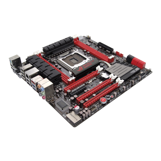
Page 28: Motherboard Overview
Motherboard overview 2.2.1 Motherboard layout Refer to 2.2.8 Internal connectors and 2.3.10 Rear panel connection for more information about rear panel connectors and internal connectors. Chapter 2: Hardware information... -
Page 29: Layout Contents
2-29 USB 2.0 connectors (10-1 pin USB910; USB1112) 2-26 Go LED 2-16 Go Button 2-14 Reset switch 2-13 Power-on switch 2-13 Digital audio connector (4-1 pin SPDIF_OUT) 2-27 Front panel audio connector (10-1 pin AAFP) 2-31 ROG RAMPAGE IV GENE... -
Page 30: Central Processing Unit (Cpu)
Contact your retailer immediately if the PnP cap is missing, or if you see any damage to the PnP cap/socket contacts/motherboard components. ASUS will shoulder the cost of repair only if the damage is shipment/ transit-related. -
Page 31: System Memory
The motherboard comes with four Double Data Rate 3 (DDR3) Dual Inline Memory Modules (DIMM) slots. A DDR3 module is notched differently from a DDR or DDR2 module. DO NOT install a DDR or DDR2 memory module to the DDR3 slot. Recommended memory configurations ROG RAMPAGE IV GENE... -
Page 32: Memory Configurations
According to Intel ® spec, the max. 32GB memory capacity can be supported with DIMMs of 8GB (or above). ASUS will update QVL once the DIMMs are available on the market. • According to Intel CPU spec, DIMM voltage below 1.65V is recommended to protect the CPU. - Page 33 RAMPAGE IV GENE Motherboard Qualified Vendors Lists (QVL) DDR3 2400 MHz capability DIMM socket support (Optional) Chip Chip Vendors Part No. Size Timing Voltage Brand 2 DIMM 3 DIMM 4 DIMM A-DATA AX3U2400GC2G10(XMP) 10-11-10-30 1.65 • • A-DATA AX3U2400GC4G10(XMP) 10-11-10-30 1.65 •...
- Page 34 RAMPAGE IV GENE Motherboard Qualified Vendors Lists (QVL) DDR3 2000 MHz capability DIMM socket support Chip (Optional) Vendors Part No. Size Chip NO. Timing Voltage Brand 2 DIMM 3 DIMM 4 DIMM A-DATA AX3U2000GB2G9B(XMP) 9-11-9-27 1.55~1.75 • • • Apacer 78.AAGD5.9KD(XMP)
- Page 35 RAMPAGE IV GENE Motherboard Qualified Vendors Lists (QVL) DDR3 1600MHz capability DIMM socket support (Optional) Chip Vendors Part No. Size Chip NO. Timing Voltage Brand DIMM DIMM DIMM A-DATA AM2U16BC2P1 A-DATA 3CCD-1509A • • • A-DATA AM2U16BC4P2 A-DATA 3CCD-1509A •...
- Page 36 RAMPAGE IV GENE Motherboard Qualified Vendors Lists (QVL) DDR3 1333MHz capability DIMM socket support Vendor Part No. Size Chip Brand Chip NO. Timing Voltage 2DIMM 4DIMM A-DATA AM2U139C4P2 A-DATA 3CCD-1509A • • CORSAIR CM3X2G1333C9 9-9-9-24 • • G.SKILL F3-10666CL8D-4GBHK(XMP) 4GB(2x2GB) 8-8-8-21 •...
-
Page 37: Expansion Slots
We recommend that you provide sufficient power when running CrossFireX™ or SLI mode. See page 2-30 for details. • Connect a chassis fan to the motherboard connector labeled CHA_FAN1/2/3 when using multiple graphics cards for better thermal environment. ROG RAMPAGE IV GENE 2-11... -
Page 38: Irq Assignments For This Motherboard
IRQ assignments for this motherboard PCIE_X16_1 shared – – – – – – – PCIE_X16_2 shared – – – – – – – PCIE_X8_3 shared – – – – – – – PCIE_X4 shared – – – – – – –... -
Page 39: Onboard Switches
This is ideal for overclockers and gamers who continually change settings to enhance system performance. Power-on switch Press the power-on switch to wake/power up the system. Reset switch Press the reset switch to reboot the system. ROG RAMPAGE IV GENE 2-13... - Page 40 GO button Press the GO button before POST to enable MemOK! or press it to quickly load the preset profile (GO_Button file) for temporary overclocking when in OS. Chapter 2: Hardware information 2-14...
-
Page 41: Onboard Leds
The LED does not light up when there is no hard disk drive connected to the motherboard or when the hard disk drive does not function. ROG RAMPAGE IV GENE 2-15... - Page 42 GO LED Blinking: Indicates that MemOK! is enabled before POST. Lighting: Indicates that the system loads the preset profile (GO_Button file) for temporary overclocking when in OS. Q LED Q LEDs check key components (CPU, DRAM, VGA card, and booting devices) in sequence during motherboard booting process.
- Page 43 The illustration below shows the location of the onboard power-on switch. Debug LEDs The Debug LED design provides you the 2-digit display, allowing you to know the system status. Refer to the Debug table below for details. ROG RAMPAGE IV GENE 2-17...
- Page 44 Debug table Code Description Not used Power on. Reset type detection (soft/hard). AP initialization before microcode loading System Agent initialization before microcode loading PCH initialization before microcode loading OEM initialization before microcode loading Microcode loading AP initialization after microcode loading System Agent initialization after microcode loading PCH initialization after microcode loading OEM initialization after microcode loading...
- Page 45 CPU DXE initialization is started PCI host bridge initialization System Agent DXE initialization is started System Agent DXE SMM initialization is started 6B – 6F System Agent DXE initialization (System Agent module specific) PCH DXE initialization is started ROG RAMPAGE IV GENE 2-19...
- Page 46 Debug table (continued) Code Description PCH DXE SMM initialization is started PCH devices initialization 73 – 77 PCH DXE Initialization (PCH module specific) ACPI module initialization CSM initialization 7A – 7F Reserved for future AMI DXE codes 80 – 8F OEM DXE initialization codes Boot Device Selection (BDS) phase is started Driver connecting is started...
- Page 47 System is waking up from the S3 sleep state System is waking up from the S4 sleep state System has transitioned into ACPI mode. Interrupt controller is in APIC mode System has transitioned into ACPI mode. Interrupt controller is in APIC mode ROG RAMPAGE IV GENE 2-21...
-
Page 48: Internal Connectors
2.2.7 Internal connectors Intel X79 Serial ATA 6.0 Gb/s connectors (7-pin SATA6G_1/2 [red]) ® These connectors connect to Serial ATA 6.0 Gb/s hard disk drives via Serial ATA 6.0 Gb/s signal cables. If you installed Serial ATA hard disk drives, you can create a RAID 0, 1, 5, and 10 configuration with the Intel Rapid Storage Technology through the onboard Intel ®... - Page 49 You must install Windows ® XP Service Pack 3 or later versions before using Serial ATA hard disk drives. The Serial ATA RAID feature is available only if you are using Windows ® XP SP3 or later versions. ROG RAMPAGE IV GENE 2-23...
- Page 50 ASMedia Serial ATA 6.0 Gb/s connectors (7-pin SATA6G_E1/E2 [red]) ® These connectors connect to Serial ATA 6.0 Gb/s hard disk drives via Serial ATA 6.0 Gb/s signal cables. • The SATA6G_E1/E2 (red) connectors are for data drives only. ATAPI device is not supported.
- Page 51 4.8Gbps connection speed. If the USB 3.0 front panel cable is available from your system chassis, with this USB 3.0 connector, you can have a front panel USB 3.0 solution. The USB 3.0 module is purchased separately. ROG RAMPAGE IV GENE 2-25...
- Page 52 Never connect a 1394 cable to the USB connectors. Doing so will damage the motherboard! You can connect the front panel USB cable to the ASUS Q-Connector (USB, blue) first, and then install the Q-Connector (USB) to the USB connector onboard if your chassis supports front panel USB ports.
- Page 53 This connector is for an additional Sony/Philips Digital Interface (S/PDIF) port. Connect the S/PDIF Out module cable to this connector, then install the module to a slot opening at the back of the system chassis. The S/PDIF module is purchased separately. ROG RAMPAGE IV GENE 2-27...
- Page 54 CPU, chassis, and power fan connectors (4-pin CPU_FAN; 4-pin CPU_OPT; 4-pin CHA_FAN1/2/3) Connect the fan cables to the fan connectors on the motherboard, ensuring that the black wire of each cable matches the ground pin of the connector. Do not forget to connect the fan cables to the fan connectors. Insufficient air flow inside the system may damage the motherboard components.
- Page 55 These connectors are for ATX power supply plugs. The power supply plugs are designed to fit these connectors in only one orientation. Find the proper orientation and push down firmly until the connectors completely fit. ROG RAMPAGE IV GENE 2-29...
- Page 56 1000W power or above to ensure the system stability. • If you are uncertain about the minimum power supply requirement for your system, refer to the Recommended Power Supply Wattage Calculator at http://support.asus. com/PowerSupplyCalculator/PSCalculator.aspx?SLanguage=en-us for details. PSU Suggested List AcBel PC7030...
-
Page 57: System Panel Connector
Pressing the power switch for more than four seconds while the system is ON turns the system OFF. • Reset button (2-pin RESET) This 2-pin connector is for the chassis-mounted reset button for system reboot without turning off the system power. ROG RAMPAGE IV GENE 2-31... -
Page 58: Building Your Computer System
Building your computer system 2.3.1 Additional tools and components to build a PC system 1 bag of screws Philips (cross) screwdriver PC chassis Power supply unit Intel LGA 2011 CPU Intel LGA 2011 compatible CPU Fan DIMM SATA hard disk drive SATA optical disc drive (optional) Graphics card The tools and components in the table above are not included in the motherboard package. -
Page 59: Cpu Installation
Please note the order in opening/ closing the double latch. Follow the instructions printed on the metal sealing hatch or the illustrations shown below in this manual. The plastic cap will pop up automatically once the CPU is in place and the hatch properly sealed down. Load lever ROG RAMPAGE IV GENE 2-33... - Page 60 Triangle mark Chapter 2: Hardware information 2-34...
-
Page 61: Cpu Heatsink And Fan Assembly Installation
2.3.3 CPU heatsink and fan assembly installation Apply the Thermal Interface Material to the CPU heatsink and CPU before you install the heatsink and fan if necessary. To install the CPU heatsink and fan assembly ROG RAMPAGE IV GENE 2-35... - Page 62 To replace the LGA2011 CPU pad (X-Socket) Chapter 2: Hardware information 2-36...
-
Page 63: Dimm Installation
2.3.4 DIMM installation To remove a DIMM ROG RAMPAGE IV GENE 2-37... -
Page 64: Motherboard Installation
2.3.5 Motherboard installation The diagrams in this section are for reference only. The motherboard layout may vary with models, but the installation steps remain the same. Chapter 2: Hardware information 2-38... - Page 65 DO NOT overtighten the screws! Doing so can damage the motherboard. ROG RAMPAGE IV GENE 2-39...
-
Page 66: Atx Power Connection
2.3.6 ATX Power connection Chapter 2: Hardware information 2-40... -
Page 67: Sata Device Connection
2.3.7 SATA device connection ROG RAMPAGE IV GENE 2-41... -
Page 68: Front I/O Connector
2.3.8 Front I/O Connector To install ASUS Q-Connector To install USB 2.0 Connector To install front panel audio connector AAFP USB 2.0 To install USB 3.0 Connector USB 3.0 Chapter 2: Hardware information 2-42... -
Page 69: Expansion Card Installation
2.3.9 Expansion Card installation To install PCIe x16 cards ROG RAMPAGE IV GENE 2-43... -
Page 70: Rear Panel Connection
2.3.10 Rear panel connection Rear panel connectors 1. PS/2 mouse and keyboard port 2. USB 2.0 ports (the white port is also for ROG Connect) 3. LAN (RJ-45) port* 4. External SATA port 5. USB 2.0 ports 6. Clear CMOS switch 7. - Page 71 Front Speaker Out Pink Mic In Mic In Mic In Mic In Orange – – Center/Subwoofer Center/Subwoofer Black – Rear Speaker Out Rear Speaker Out Rear Speaker Out Gray – – – Side Speaker Out ROG RAMPAGE IV GENE 2-45...
-
Page 72: Audio I/O Connections
2.3.11 Audio I/O connections Audio I/O ports Connect to Headphone and Mic Connect to Stereo Speakers Connect to 2.1 channel Speakers Chapter 2: Hardware information 2-46... - Page 73 Connect to 4.1 channel Speakers Connect to 5.1 channel Speakers Connect to 7.1 channel Speakers ROG RAMPAGE IV GENE 2-47...
-
Page 74: Starting Up For The First Time
Starting up for the first time After making all the connections, replace the system case cover. Be sure that all switches are off. Connect the power cord to the power connector at the back of the system chassis. Connect the power cord to a power outlet that is equipped with a surge protector. Turn on the devices in the following order: Monitor External SCSI devices (starting with the last device on the chain) -
Page 75: Chapter 3: Bios Setup
BIOS setup Knowing BIOS The new ASUS UEFI BIOS is an Unified Extensible Firmware Interface that complies with UEFI architecture, offering a user-friendly interface that goes beyond traditional keyboard- only BIOS controls to enable more flexible and convenient mouse input. Users can easily navigate the new UEFI BIOS with the same smoothness as their operating system. -
Page 76: Advanced Mode
The Advanced Mode provides advanced options for experienced end-users to configure the BIOS settings. The figure below shows an example of the Advanced Mode. Refer to the following sections for the detailed configurations. To access the EZ Mode, click Exit, then select ASUS EZ Mode. Menu bar Menu items... -
Page 77: Menu Items
You cannot select an item that is not user-configurable. A configurable field is highlighted when selected. To change the value of a field, select it and press <Enter> to display a list of options. ROG RAMPAGE IV GENE... -
Page 78: Ez Mode
Power Saving mode Loads optimized default Displays the system properties of the Normal mode ASUS Optimal mode selected mode on the right hand side • The boot device options vary depending on the devices you installed to the system. The Boot Menu(F8) button is available only when the boot device is installed to the •... -
Page 79: Extreme Tweaker Menu
Be cautious when changing the settings of the Extreme Tweaker menu items. Incorrect field values can cause the system to malfunction. The configuration options for this section vary depending on the CPU and DIMM model you installed on the motherboard. Scroll down to display the following items: ROG RAMPAGE IV GENE... - Page 80 Scroll down to display the following items: Load Normal OC Profile OverClock Template Suitable for day to day gamers. Load Gamers’ OC Profile OverClock Template Suitable for day to day gamers. Load Extreme OC Profile (Low Current) Sets sweet-spot settings for Extreme overclocking and sinks current away from the processor to preserve its life-span.
-
Page 81: Dram Timing Control
Changing the values in this menu may cause the system to become unstable! If this happens, revert to the default settings. Load Elipida Hyper Profile Change settings to suit Elpida Hyper Profile by selecting Yes. Load Tight PSC Profile Change settings to suit Tight PSC Profile by selecting Yes. ROG RAMPAGE IV GENE... - Page 82 Load Loose PSC Profile Change settings to suit Loose PSC Profile by selecting Yes. Load Tight 4x4GB Hynix Profile Change settings to suit Tight 4x4GB Hynix Profile by selecting Yes. Load RAW MHZ Profile Change settings to suit RAW MHZ Profile by selecting Yes. Rampage Tweak [Auto] Mode 1 can help Memory Compatibility.
- Page 83 [Auto] Configuration options: [Auto] [0 DRAM Clock] – [15 DRAM Clock] tWRDR [Auto] Configuration options: [Auto] [0 DRAM Clock] – [7 DRAM Clock] tWRDD [Auto] Configuration options: [Auto] [0 DRAM Clock] – [7 DRAM Clock] ROG RAMPAGE IV GENE...
- Page 84 tRWSR [Auto] Configuration options: [Auto] [0 DRAM Clock] – [15 DRAM Clock] tCCD [Auto] Configuration options: [Auto] [0 DRAM Clock] – [7 DRAM Clock] Latency Timings DRAM RTL (CHA/B/C/D D0/1 R0/1 [Auto]) Configuration options: [Auto] [Advance 14 Clock] [Advance 12 Clock] – [Advance 4 Clock] [Advance 2 Clock] [Normal] [Delay 2 Clock] [Delay 4 Clock] –...
- Page 85 CPU and VRM thermal. This item allows you to adjust the voltage range from the following percentages to boost the system performance: 0% (Regular), 25% (Medium), 50% (High), 75% (Ultra High) and 100% (Extreme). Configuration options: [Auto] [Regular] [Medium] [High] [Ultra High] [Extreme] ROG RAMPAGE IV GENE 3-11...
- Page 86 VRM efficiency [Auto] The default power control phase mode [Standard] Proceeds phase control depending on the CPU loading. [Optimized] Loads the ASUS optimized phase tuning profile. [Extreme] Proceeds the full phase mode. [Manual Adjustment] Allows manual adjustment. CPU Spread Spectrum [Disabled]...
- Page 87 DRAM-AB/DRAM-CD Power Phase control [Auto] [Auto] Allows you to set the default DRAM power phase control settings. [Optimized] Allows you to set ASUS optimized phase tuning profile. [Extreme] Allows you to set the Full phase mode. PCH 1.1V PCH 1.1v Switching Freq. [Auto] This item allows you to switch the frequency of PCH power.
-
Page 88: Cpu Performance Settings
CPU Performance Settings CPU Ratio [Auto] Allows you to manually adjust the maximum non-turbo CPU ratio. Use <+> and <-> keys to adjust the value. The valid value ranges vary according to your CPU model. Enhanced Intel SpeedStep Technology [Enabled] Allows you to enable or disable the Enhanced Intel SpeedStep Technology. -
Page 89: Offset Mode Sign
Offset Mode Sign [+] This item appears only when you set the CPU VCORE Voltage item to [Offset Mode]. To offset the voltage by a positive value. [–] To offset the voltage by a negative value. ROG RAMPAGE IV GENE 3-15... - Page 90 CPU VCORE Offset Voltage [Auto] This item allows you to set the Offset voltage. The values range from 0.005V to 0.635V with a 0.005V interval. VTT CPU Voltage [Auto] Allows you to set the VTT CPU voltage. The values range from 0.8000V to 1.7000V with a 0.00625V interval.
- Page 91 Enhances the BCLK overclocking ability. [Enabled] Sets to [Enabled] for EMI control. PCIE Spread Spectrum [Auto] [Auto] Sets to default PCIE spread spectrum configuration. [Disabled] Enhances the PCIE overclocking ability. [Enabled] Sets to [Enabled] for EMI control. ROG RAMPAGE IV GENE 3-17...
- Page 92 Memory Tweakers’ Paradise Scroll down to display the following items: IMC AB/CD Signal 1/2/3 [Auto] Configuration options: [-126] – [-1] [Auto] [+1] – [+32] DRAM CTRL REF Voltage on CHA/B/C/D The values range from 0.3950x to 0.6300x with a 0.0050x interval. DRAM DATA REF Voltage on CHA/B/C/D The values range from 0.3950x to 0.6300x with a 0.0050x interval.
-
Page 93: Main Menu
System Language [English] Allows you to choose the BIOS language version from the options. 3.4.2 System Date [Day xx/xx/xxxx] Allows you to set the system date. 3.4.3 System Time [xx:xx:xx] Allows you to set the system time. ROG RAMPAGE IV GENE 3-19... -
Page 94: Security
3.4.4 Security The Security menu items allow you to change the system security settings. • If you have forgotten your BIOS password, erase the CMOS Real Time Clock (RTC) RAM to clear the BIOS password. See section 2.3.10 Rear panel connection for information on how to erase the RTC RAM. -
Page 95: User Password
To clear the user password, follow the same steps as in changing a user password, but press <Enter> when prompted to create/confirm the password. After you clear the password, the User Password item on top of the screen shows Not Installed. ROG RAMPAGE IV GENE 3-21... -
Page 96: Advanced Menu
Advanced menu The Advanced menu items allow you to change the settings for the CPU and other system devices. Be cautious when changing the settings of the Advanced menu items. Incorrect field values can cause the system to malfunction. Chapter 3: BIOS setup 3-22... -
Page 97: Cpu Configuration
[Disabled] Only one thread per activated core is enabled. [Enabled] Two threads per activated core are enabled. ROG RAMPAGE IV GENE 3-23... -
Page 98: Cpu Power Management Configuration
Active Processor Cores [All] Allows you to choose the number of CPU cores to activate in each processor package. Configuration options: [All] [1] [2] [3] [4] [5] Limit CPUID Maximum [Disabled] [Enabled] Allows legacy operating systems to boot even without support for CPUs with extended CPUID functions. -
Page 99: System Agent Configuration
Select Target Link Speed Gen1, Gen2 or Gen3. Configuration options: [GEN1] [GEN2] [GEN3] 3.5.3 PCH Configuration High Precision Timer [Enabled] Allows you to enable or disable the High Precision Event Timer. Configuration options: [Disabled] [Enabled] ROG RAMPAGE IV GENE 3-25... -
Page 100: Sata Configuration
3.5.4 SATA Configuration While entering Setup, the BIOS automatically detects the presence of SATA devices. The SATA Port items show Not Present if no SATA device is installed to the corresponding SATA port. SATA Mode [AHCI Mode] Allows you to set the SATA configuration. [Disabled] Disables the SATA function. -
Page 101: Usb Configuration
Disables the function. [Enabled] Enables the support for USB 3.0 devices on legacy operating systems (OS). EHCI Hand-off [Disabled] [Disabled] Disables the function. [Enabled] Enables the support for operating systems without an EHCI hand-off feature. ROG RAMPAGE IV GENE 3-27... -
Page 102: Onboard Devices Configuraton
3.5.6 Onboard Devices Configuraton Azalia HD Audio [Enabled] [Disabled] Disables the controller. [Enabled] Enables the High Definition Audio Controller. The following two items appear only when you set the Azalia HD Audio item to [Enabled]. Front Panel Type [HD] Allows you to set the front panel audio connector (AAFP) mode to legacy AC97 or high- definition audio depending on the audio standard that the front panel audio module supports. - Page 103 ASM1061 Storage OPROM [Enabled] This item appears only when you set the previous item to [IDE Mode] or [AHCI Mode] and allows you to enable or disable the OptionRom of the ASM1061 storage controller. Configuration options: [Disabled] [Enabled] ROG RAMPAGE IV GENE 3-29...
-
Page 104: Apm
3.5.7 Restore AC Power Loss [Power Off] [Power On] The system goes into on state after an AC power loss. [Power Off] The system goes into off state after an AC power loss. [Last State] The system goes into either off or on state, whatever the system state was before the AC power loss. -
Page 105: Monitor Menu
CPU Temperature; MB Temperature; PCH Temperature; PCH Overheat Protection[xxxºC/xxxºF] The onboard hardware monitor automatically detects and displays the CPU, motherboard, and the assigned devices temperatures. Select [Ignored] if you do not wish to display the detected temperatures. ROG RAMPAGE IV GENE 3-31... -
Page 106: Fan Speed Control
Fan Speed Monitor CPU FAN Speed; CPU OPT Speed; Chassis FAN1/2/3 Speed [xxxxRPM] or [Ignored] / [N/A] The onboard hardware monitor automatically detects and displays the CPU fan, chassis fan, and optional fan speed in rotations per minute (RPM). If any of the fans is not connected to the motherboard, the field shows [N/A]. - Page 107 Use the <+> and <-> keys to adjust the minimum chassis fan duty cycle. The values range from 0% to 100%. When the chassis temperature is under 40ºC, the chassis fan will operate at the minimum duty cycle. ROG RAMPAGE IV GENE 3-33...
-
Page 108: Boot Menu
Full Screen Logo [Enabled] [Enabled] Enables the full screen logo display feature. [Disabled] Disables the full screen logo display feature. Set this item to [Enabled] to use the ASUS MyLogo 2™ feature. Wait For ‘F1’ If Error [Enabled] [Disabled] Disables this function. [Enabled] The system waits for the <F1>... -
Page 109: Boot Option Priorities
• To select the boot device during system startup, press <F8> when ASUS Logo appears. • To access Windows OS in Safe Mode, press <F8> after POST. -
Page 110: Tools Menu
<Enter> to display the submenu. 3.8.1 ASUS EZ Flash 2 Utility Allows you to run ASUS EZ Flash 2 Utility. When you press <Enter> to start the application. For more details, refer to section 3.10.2 ASUS EZ Flash 2 Utility. Chapter 3: BIOS setup... -
Page 111: Asus Spd Information
3.8.2 ASUS SPD Information Allows you to get DRAM SPD information. ROG RAMPAGE IV GENE 3-37... -
Page 112: Asus O.c. Profile
3.8.3 ASUS O.C. Profile This item allows you to store or load multiple BIOS settings. The Setup Profile Status items show Not Installed if no profile is created. Label Allows you to input the label of setup profile. Save to Profile Allows you to save the current BIOS settings to the BIOS Flash, and create a profile. -
Page 113: Go Button File
Allows you to load default settings. Save Above Settings Allows you to save the adjusted values for specific items as a GO Button file. Load from EEPROM settings Allows you to load from EEPROM setting. ROG RAMPAGE IV GENE 3-39... -
Page 114: Exit Menu
This option allows you to exit the Setup program without saving your changes. When you select this option or if you press <Esc>, a confirmation window appears. Select Yes to discard changes and exit. ASUS EZ Mode This option allows you to enter the EZ Mode screen. Launch EFI Shell from filesystem device This option allows you to attempt to launch the EFI Shell application (shellx64.efi) from one of... -
Page 115: Updating Bios
BIOS in the future. Copy the original motherboard BIOS using the ASUS Update or BIOS Updater utilities. 3.10.1 ASUS Update utility The ASUS Update is a utility that allows you to manage, save, and update the motherboard BIOS in Windows environment. The ASUS Update utility allows you to: ®... -
Page 116: Updating The Bios Through The Internet
To update the BIOS through the Internet: From the ASUS Update screen, select Update BIOS from Internet, and then click Next. Select the ASUS FTP site nearest you to avoid network traffic. If you want to enable the BIOS downgradable function and auto BIOS backup function, check the checkbox before the two items on the screen. - Page 117 Click Browse to locate your desired picture file. Adjust the picture resolution if needed and click Next to continue. Follow the onscreen instructions to complete the update process. ROG RAMPAGE IV GENE 3-43...
-
Page 118: Updating The Bios Through A Bios File
The screenshots in this section are for reference only. The actual BIOS information vary by models. • Refer to the software manual in the support DVD or visit the ASUS website at www. asus.com for detailed software configuration. Chapter 3: BIOS setup... -
Page 119: Asus Ez Flash 2 Utility
3.10.2 ASUS EZ Flash 2 Utility The ASUS EZ Flash 2 Utility feature allows you to update the BIOS without having to use a bootable floppy disk or an OS-based utility. Before you start using this utility, download the latest BIOS from the ASUS website at www. -
Page 120: Asus Crashfree Bios 3 Utility
The BIOS file in the motherboard support DVD may be older than the BIOS file published on the ASUS official website. If you want to use the newer BIOS file, download the file at support.asus.com and save it to a USB flash drive. -
Page 121: Asus Bios Updater
3.10.4 ASUS BIOS Updater The ASUS BIOS Updater allows you to update BIOS in DOS environment. This utility also allows you to copy the current BIOS file that you can use as a backup when the BIOS fails or gets corrupted during the updating process. -
Page 122: Backing Up The Current Bios
Backing up the current BIOS To backup the current BIOS file using the BIOS Updater Ensure that the USB flash drive is not write-protected and has enough free space to save the file. At the FreeDOS prompt, type bupdater /o[filename] and press <Enter>. D:\>bupdater /oOLDBIOS1.rom Filename Extension The [filename] is any user-assigned filename with no more than eight alphanumeric... -
Page 123: Updating The Bios File
Select the Load Optimized Defaults item under the Exit BIOS menu. See Chaper 3 of your motherboard user manual for details. • Ensure to connect all SATA hard disk drives after updating the BIOS file if you have disconnected them. ROG RAMPAGE IV GENE 3-49... -
Page 124: Usb Bios Flashback
The USB BIOS Flashback allows user to update the BIOS without entering the BIOS or the operating system by using a USB flash disk drive under standby power. Download the latest BIOS file from the ASUS website Extract and rename the BIOS image file to “R4G.ROM”... -
Page 125: Installing An Operating System
The contents of the support DVD are subject to change at any time without notice. Visit the ASUS website at www.asus.com for updates. 4.2.1 Running the support DVD Place the support DVD into the optical drive. -
Page 126: Obtaining The Software Manuals
® Acrobat Reader from the Utilities menu before opening the files. ® Click on the Manual tab. Click on ASUS Motherboard Utility Guide from the manual list on the left. The Manual folder of the support DVD appears. Double-click the folder of your selected software. -
Page 127: Software Information
4.3.1 AI Suite II AI Suite II is an all-in-one interface that integrates several ASUS utilities and allows users to launch and operate these utilities simultaneously. Installing AI Suite II To install AI Suite II on your computer Place the support DVD to the optical drive. -
Page 128: Turbov Evo
After installing AI Suite II from the motherboard support DVD, launch TurboV EVO by clicking Tool > TurboV EVO on the AI Suite II main menu bar. Refer to the software manual in the support DVD or visit the ASUS website at www.asus.com for detailed software configuration. - Page 129 Set the CPU Ratio Setting item in BIOS to [Auto] before using the CPU Ratio function • in TurboV. Refer to Chapter 3 of your motherboard user manual for details. • The CPU Ratio bars show the status of the CPU cores, which vary with your CPU model. ROG RAMPAGE IV GENE...
-
Page 130: Cpu Level Up
• The value on the CPU Strap diagram varies with your CPU model. CPU Level Up ASUS TurboV EVO includes three CPU level up modes, providing the most flexible auto- tuning options. • The overclocking result varies with the CPU model and the system configuration. - Page 131 Read through the warning messages and click OK to start auto-overclocking. TurboV automatically adjusts and saves BIOS settings and restarts the system. After re-entering Windows, a message appears indicating auto tuning success. Click OK to exit. ROG RAMPAGE IV GENE...
- Page 132 Using 3.900 Ghz mode Tick the 3.900 GHz, and click Start. Read through the warning messages and click OK to start auto-overclocking. TurboV automatically adjusts and saves BIOS settings and restarts the system. After re-entering Windows, a message appears indicating auto tuning success. Click OK to exit.
-
Page 133: Digi+ Power Control
CPU Power Phase Control Increase phase number under heavy system loading to get more transient and better thermal performance. Reduce phase number under light system loading to increase VRM efficiency. ROG RAMPAGE IV GENE... - Page 134 Function no. Function description CPU Power Duty Control CPU Power Duty Control adjusts the current of every VRM phase and the thermal of every phase component. DRAM Power Application aids Apply all changes immediately Undo all changes without applying Function no. Function description DRAM Current Capability A higher value brings a wider total power range and extends the...
-
Page 135: Epu
Select From the Last Reset to show the total CO2 that has been reduced since you click the Clear button • Refer to the software manual in the support DVD or visit the ASUS website at www.asus.com for detailed software configuration. ROG RAMPAGE IV GENE... -
Page 136: Fan Xpert
However, the fan will speed up when the temperature exceeds 70°C. User: Allows you to configure the CPU fan profile under certain limitations. • Refer to the software manual in the support DVD or visit the ASUS website at www.asus.com for detailed software configuration. Chapter 4: Software support... -
Page 137: Sensor Recorder
Click on Recording to record the history changes. Click on Monitor > Sensor on the AI Suite II main menu bar and a highlight of the system statuses will appear on the right panel. ROG RAMPAGE IV GENE 4-13... -
Page 138: Probe Ii
Loads your saved Applies your Loads the default configuration changes threshold values for each sensor Refer to the software manual in the support DVD or visit the ASUS website at www.asus.com for detailed software configuration. Chapter 4: Software support 4-14... - Page 139 The Temperature tab displays the CPU and motherboard temperature sensors, including the current and threshold values. When the CPU/MB temperature exceeds the threshold temperature, the sensor sends an alert to the user through the monitor panels or a pop-up message. ROG RAMPAGE IV GENE 4-15...
- Page 140 Fan Speed The Fan Speed tab displays the current and threshold rotations (per minute) of the CPU, chassis, and power fans. When a fan rotation is less than the threshold rotation, the sensor sends an alert to the user through the monitor panels or a pop-up message. Preference The Preference tab allows you to enable the pop-up window, set the cycle detection interval, and select the temperature scale.
- Page 141 Alert Log The Alert Log tab displays all normal and critical events detected by the sensors, including the sensor value at the time of the event. Click Clear to clear the log. ROG RAMPAGE IV GENE 4-17...
-
Page 142: Usb 3.0 Boost
4.3.8 USB 3.0 Boost The ASUS exclusive USB 3.0 Boost provides speed boost for USB 3.0 devices and the up-to-date support of USB Attached SCSI Protocol (UASP). With USB 3.0 Boost, you can accelerate the transfer speed of your USB 3.0 devices with ease. -
Page 143: Ai Charger
* Check your USB device manufacturer if it fully supports the BC 1.1 function. • ** The actual charging speed may vary with your USB device’s conditions. • Ensure to remove and reconnect your USB device after enabling or disabling Ai Charger+ to ensure normal charging function. ROG RAMPAGE IV GENE 4-19... -
Page 144: Asus Update
4.3.10 ASUS Update ASUS Update lays out the options for updating BIOS on your system. Update BIOS utility on your system or simply save the utility for later use just by following the directions on this convenient updating feature. Launching ASUS Update After installing AI Suite II from the motherboard support DVD, launch ASUS Update by clicking Update>... -
Page 145: Mylogo2
Select the way you would like to do update your boot logo. Then click Next and follow the given instructions. Change the BIOS boot logo of my motherboard Under Current BIOS, click Browse and choose the desired image for your boot logo. Then click on Next. ROG RAMPAGE IV GENE 4-21... - Page 146 Click on Auto Tune to adjust image size compatibility or adjust the resolution bar. You can click on Booting Preview to preview the boot image. Then click Next. Click on Flash to start updating the image to the boot logo. Click on Yes to reboot or you can also see the new logo next time you restart your computer.
-
Page 147: Rog Connect
Press the ROG Connect Button and it will light up into a stable glow. Double-click the RC TweakIt shortcut on the remote PC to activate the function Using RC TweakIt Use the sliders and buttons to monitor or adjust your local PC. ROG RAMPAGE IV GENE 4-23... - Page 148 Click Function to display more options. RC Poster RC Poster shows the status of the local system during the POST. You can switch the display mode between String and Code. RC Remote RC Remote allows you to operate your local system through the ROG Connect cable.
- Page 149 GPU TweakIt GPU TweakIt allows you to control and monitor the installed GPU on the local system. Use the sliders to adjust the values and click Apply to save your customized settings. ROG RAMPAGE IV GENE 4-25...
-
Page 150: Audio Configurations
Realtek HD Audio Manager for Windows XP Exit button Configuration options Minimize button Control settings window Information button Refer to the software manual in the support DVD or visit the ASUS website at www.asus.com for detailed software configuration. Chapter 4: Software support 4-26... -
Page 151: Sound Blaster X-Fi Mb 2
After installing Sound Blaster X-Fi MB 2 successfully, you need to activate this utility online before first use. Double-click Activate on the desktop. Ensure that you have successfully installed the LAN driver and have connected to the Internet. Click Activate to start activation. ROG RAMPAGE IV GENE 4-27... - Page 152 Using Sound Blaster X-Fi MB 2 Speaker and Headphone Equalizer Mixer Adjusting Volume Restoring to the Default Mute Speaker and Headphone You can adjust the speaker-related or the headphone- related configurations. Environment audio extensions (EAX) After enabling the EAX effects, you are allowed to select and add your desired environment sounds into the music.
- Page 153 You can manually adjust the audio volumes, including Line In, Stereo Mix and Microphone, when recording or during the playback. THX is a high-fidelity sound technology that allows you to adjust the surround sound effect, sub-woofer volume, etc.. ROG RAMPAGE IV GENE 4-29...
-
Page 154: Raid Configurations
RAID configurations The motherboard supports the Intel Rapid Storage Technology with RAID 0, RAID 1, ® RAID 10 and RAID 5 support. • You must install Windows XP Service Pack 3 or later versions before using Serial ® ATA hard disk drives. The Serial ATA RAID feature is available only if you are using Windows XP SP3 or later versions. -
Page 155: Installing Serial Ata Hard Disks
Turn on the system. During POST, press <Ctrl> + <I> to display the utility main menu. Intel(R) Rapid Storage Technology - Option ROM - v10.0.0.1032 Copyright(C) 2003-10 Intel Corporation. All Rights Reserved. [ MAIN MENU ] 1. Create RAID Volume 3. Reset Disks to Non-RAID 2. Delete RAID Volume 4. Recovery Volume Options 5. Exit [ DISK/VOLUME INFORMATION ] RAID Volumes: None defined. Physical Devices: Port Device Model Serial # Size Type/Status(Vol ID) 0 ST3160812AS 9LS0HJA4 149.0GB Non-RAID Disk 1 ST3160812AS 9LS0F4HL 149.0GB Non-RAID Disk 2 ST3160812AS 3LS0JYL8 149.0GB Non-RAID Disk 3 ST3160812AS 9LS0BJ5H 149.0GB Non-RAID Disk [↑↓]-Select [ESC]-Exit [ENTER]-Select Menu ROG RAMPAGE IV GENE 4-31... -
Page 156: Creating A Raid Set
The navigation keys at the bottom of the screen allow you to move through the menus and select the menu options. The RAID BIOS setup screens shown in this section are for reference only and may not exactly match the items on your screen. The utility supports maximum four hard disk drives for RAID configuration. - Page 157 When the Create Volume item is selected, press <Enter>. The following warning message appears: WARNING: ALL DATA ON SELECTED DISKS WILL BE LOST. Are you sure you want to create this volume? (Y/N): Press <Y> to create the RAID volume and return to the main menu, or <N> to go back to the CREATE VOLUME menu. ROG RAMPAGE IV GENE 4-33...
-
Page 158: Deleting A Raid Set
Deleting a RAID set Take caution when deleting a RAID set. You will lose all data on the hard disk drives when you delete a RAID set. To delete a RAID set: From the utility main menu, select 2. Delete RAID Volume and press <Enter>. The following screen appears: Intel(R) Rapid Storage Technology - Option ROM - v10.0.0.1032 Copyright(C) 2003-10 Intel Corporation. All Rights Reserved. -
Page 159: Creating A Raid Driver Disk
Launch Windows File Manager and locate the following path in the support DVD: \Drivers\RAID\RSTe\Driver Double-click AsMakeDisk.exe to launch the ASUS MakeDisk Utility. Select the USB floppy disk drive as the destination disk. Follow the succeeding screen instructions to complete the process. -
Page 160: Installing The Raid Driver During Windows ® Os Installation
4.5.3 Installing the RAID driver during Windows OS installation ® To install the RAID driver in Windows ® During the OS installation, the system prompts you to press the F6 key to install third- party SCSI or RAID driver. Press <F6>, and then insert the floppy disk with RAID driver into the USB floppy disk drive. When prompted to select the SCSI adapter to install, select the RAID driver for the corresponding OS version. -
Page 161: Using A Usb Floppy Disk Drive
Product ID (PID) are displayed. Browse the contents of the RAID driver disk to locate the file txtsetup.oem. Double-click the file. A window appears, allowing you to select the program for opening the oem file. ROG RAMPAGE IV GENE 4-37... - Page 162 Use Notepad to open the file. Find the [HardwareIds.scsi.iaAHCI_DesktopWorkstationServer] and [HardwareIds.scsi.iaStor_DesktopWorkstationServer] sections in the txtsetup.oem file. Type the following line to the bottom of the two sections: id = “USB\VID_xxxx&PID_xxxx”, “usbstor” [HardwareIds.scsi.iaAHCI_DesktopWorkstationServer] id= “PCI\VEN_8086&DEV_1C02&CC_0106”,”iaStor” id= “USB\VID_03EE&PID_6901”, “usbstor” [HardwareIds.scsi.iaStor_DesktopWorkstationServer] id= “PCI\VEN_8086&DEV_2822&CC_0104”,”iaStor” id= “USB\VID_03EE&PID_6901”, “usbstor” Add the same line to both sections. The VID and PID vary with different vendors.
-
Page 163: Chapter 5: Multiple Gpu Technology Support
For Windows XP, go to Control Panel > Add/Remove Programs. For Windows Vista, go to Control Panel > Programs and Features. Select your current graphics card driver/s. For Windows XP, select Add/Remove. For Windows Vista, select Uninstall. Turn off your computer. ROG RAMPAGE IV GENE... -
Page 164: Installing Two Crossfirex™ Graphics Cards
5.1.3 Installing two CrossFireX™ graphics cards The following pictures are for reference only. The graphics cards and the motherboard layout may vary with models, but the installation steps remain the same. Prepare two CrossFireX-ready graphics cards. Insert the two graphics card into the PCIEX16 slots. -
Page 165: Installing The Device Drivers
Graphics Settings > Performance > AMD CrossFireX Configuration. From the Graphics Adapter list, select the graphics card to act as the display GPU. Select Enable CrossFireX Click Apply, and then click OK to exit the window. ROG RAMPAGE IV GENE... -
Page 166: Nvidia ® Sli™ Technology
NVIDIA SLI™ technology ® The motherboard supports the NVIDIA SLI™ (Scalable Link Interface) technology that ® allows you to install multi-graphics processing units (GPU) graphics cards. Follow the installation procedures in this section. 5.2.1 Requirements • In SLI mode, you should have two identical SLI-ready graphics cards that are NVIDIA ®... -
Page 167: Installing The Device Drivers
You can launch the NVIDIA Control Panel by the following two methods. Right click on the empty space of the Windows desktop ® and select NVIDIA Control Panel. The NVIDIA Control Panel window appears (See Step B5). ROG RAMPAGE IV GENE... - Page 168 If you cannot see the NVIDIA Control Panel item in step (A), select Personalize. From the Personalization window, select Display Settings. From the Display Settings dialog box, click Advanced Settings. Chapter 5: Multiple GPU technology support...
- Page 169 Panel. The NVIDIA Control Panel window appears. Enabling SLI settings From the NVIDIA Control Panel window, select Set SLI Configuration. Click Enable SLI and set the display for viewing SLI rendered content. When done, click Apply. ROG RAMPAGE IV GENE...
- Page 170 Chapter 5: Multiple GPU technology support...
-
Page 171: Asus Contact Information
+1-812-282-3777 +1-510-608-4555 Web site usa.asus.com Technical Support Telephone +1-812-282-2787 Support fax +1-812-284-0883 Online support support.asus.com ASUS COMPUTER GmbH (Germany and Austria) Address Harkort Str. 21-23, D-40880 Ratingen, Germany +49-2102-959911 Web site www.asus.de Online contact www.asus.de/sales Technical Support Telephone (Component) +49-1805-010923*...