Table of Contents
Advertisement
Quick Links
SEARS
OWNER'S
MANUAL
MODEL NO.
390.2.532
CAUTION:
Read and Follow
All Safety Rulesand
Operating Instructions
Before First Use of
ThisProduct.
Save ThisManual For
Future Reference.
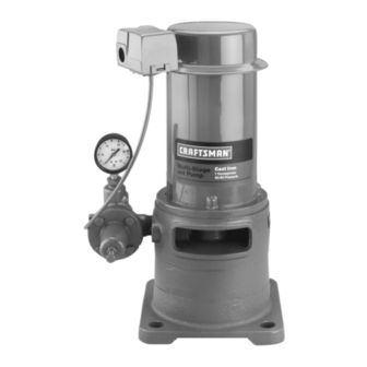
I:RRFTIMRN °
MULTI-STAGE JET PUMP
• Safety Instructions
• Installation
• Electrical
• Operation
• Maintenance
• Repair Parts
Sears, Roebuck and Co., Hoffman Estates, IL 60179
U.S.A.
PRINTED
IN
U.S.A.
Form No.
F642-040T7
(8/6/04)
Advertisement
Table of Contents

Related Manuals for Craftsman 390.2532


Summary of Contents for Craftsman 390.2532
- Page 1 SEARS OWNER'S MANUAL MODEL NO. 390.2.532 I:RRFTIMRN ° CAUTION: MULTI-STAGE JET PUMP Read and Follow All Safety Rulesand Operating Instructions • Safety Instructions Before First Use of • Installation ThisProduct. • Electrical Save ThisManual For • Operation Future Reference. • Maintenance •...
- Page 2 CONTENTS INTRODUCTION INTRODUCTION/WARRANTY ........Please read our instructions before installing and using MAJOR COMPONENTS ..........your Deep Well Jet Pump. This will help you obtain the full benefits of the quality and convenience built into PUMP PERFORMANCE ..........this equipment. It will also help you avoid any needless INSTALLATION ............
- Page 3 MAJOR COMPONENTS WHAT THEY Tank and Air Volume Control Adapter Flange The tank serves two functions: The VMS pump is equipped with an adapter flange. This adapter facilitates installation and removal of the It provides a reservoir of water. Some of this water pump without disturbing...
- Page 4 PUMP PERFORMANCE Multi-Stage Pump Pump Performance (in gallons per minute) Pump Discharge Stock Pkg. Pressure Pumping Depth In Feet P.S,I, 2967* 11.3 10,0 10.6 390.2532 29902**t 11.7 11.1 10.2 1 HP 11.0 29660*** 11.7 11.1 10.2 11.O Use 160 PSI Min. Rating Plastic Pipe. * Jet Package No.
- Page 5 INSTALLATION NOTICE: For proper performance, pump MUST be Piping In The Deep Well matched to ejector and to well depth. Use this pump See Figures 6, 7, and 8. on wells 25' to 210' deep. NOTICE: Deep well instaUations are either single pipe Long runs and many fittings increase friction and re- (2"...
- Page 6 INSTALLATION Thread a 1" plastic pipe adapter or a 1" nipple into 12. Remove paper backing from adhesive gasket. Apply the 1" tapped hole in ejector body (see lfigure 8). gasket to adapter flange, making sure that holes line Install sufficient plastic pipe in well casing to place ejector at the...
- Page 7 INSTALLATION which may occur in the piping and foot valve as the Discharge Pipe Sizes piping is assembled. If increasing discharge pipe size, install reducer pump discharge port. Do not increase pipe size by Single Pipe Ejector Installation stages. Single pipe installations require (see Figure 9): When the pump...
- Page 8 PRESSURE TANK CONNECTION ELECTRICAL Precharged Tank Connection Disconnect power before working When a precharged tank is used, no AVC is necessary pump, motor, pressure switch, or wiring. See Figure 12 for typical precharged tank installation. A precharged tank contains a factory provided Motor Switch...
- Page 9 ELECTRICAL To change I 15 volts: ranty. The supply voltage must be within +10% of the motor nameplate voltage. 1. Make sure power is off. NOTICE: Dual-voltage motors are factory wired 2. Pull the ping toward you. 230 volts. If necessary, reconnect the motor for 115...
- Page 10 OPERATION Priming Pump Start Pinup: Pressure should increase rapidly to 50 pounds I&WARNING ]Burn hazard. NEVER pump dry. square inch or more as ejector and pump prime. Running pump without water cause pump so, go to step 4, below. to overheat, damaging seal and possibly...
- Page 11 OPERATION HELPFUL HINTS / MAINTENANCE Once unit has primed pressure stabilized, slowly open (turn counterclockwise - Figure 19A, To Handle A Gaseous Well regulator valve until pressure falters (pressure gauge needle flutters; pump may become noisy- see In some areas well water contains gases which must be Figure 1913).
- Page 12 MAINTENANCE Using the Compound Gauge Pump Diassembly If the pump or system seems to be operating ineffi- Pull disconnect switch. Disconnect power lines ciently, the compound gauge can sometimes help de- from pressure switch. termine the problem. Remove the two cap screws holding the pump A compound...
- Page 13 MAINTENANCE 1 I. Remove the intermediate volute and slide the im- Hold the motor shaft with pliers or vice grips peller spacer off of the shaft. fllrough the opening in the pump adapter. Unscrew the impeller nut off the end of the shaft (see Figure 12.
- Page 14 HAINTENANCE Carefully slide the adapter over shaft (see Install the intermediate volute, aligning it with the Figure 27). Do not damage the shaft sealing surface; mark made before disassembly. Use the long cap it is highly polished and any slight scratches or nicks screws to check...
- Page 15 TROUBLESHOOTING CHART SYMPTOM POSSIBLE CAUSE(S) CORRECTIVE ACTION Motor will not run 1. Disconnect switch is off 1. Be sure switch is on 2. Fuse is blown 2. Replace fuse 3. Starting switch is defective 3. Replace starting switch 4. Wires at motor are loose, discon- 4.
- Page 16 REPAIR PARTS Multi-Stage Jet Pump -14C --12 @--11 1281 0994 Repair Parts List - Multi-Stage Part Part Number Description 1"* J218-600C Motor L43-5C Connector U36-112ZP Locknut - 1/2" U217-1228 Pressure Switch U37-672P Switch Tube - 14-1/2" J212-24A Pressure Regulator Assembly L2-16A Adapter U30-75ZP...
- Page 17 REPAIR PARTS Pressure Regulator Call Sears Product Service, To Order Parts, 1-800.366-7278 Repair Parts List - Pressure Regulator Part Number Part Description Jl12-14 Pressure Regulator Body w/Seat U111-212T Barbed Fitting - Elbow J66-16 Valve Seat J220-16B Diaphragm Assembly J42-5 Regulator Guide J62-9 Stem J20-16...
- Page 18 REPAIR PARTS Vertical Casing Adapters and Adapter Flanges To Order Parts, for Multi-Stage Jet Pump Call Sears Product Service, 1-800-366-7278 489 0194 Adapter Flange Casing Adapter Repair Parts List - Adapter Flange Part Number Part Description J20-12 Adapter Gasket J2-17B Adapter- 1-1/4"x1-1-1/4"...
- Page 19 REPAIR PARTS Jet Packages 4" Double Pipe Jets 2" and 3" Single Pipe Jets Suction Pipe Drive Pipe: Adapter ipple Well .Drop Pipe 1 • Pipe- Adapter "*--3 1361 1094 Repair Parts List - Jet Packages 13801 o94 2967 29902 29660 4"...
- Page 20 OWNER'S CRAFTSMAN+ MANUAL MULTI-STAGE JET PUMP Model No. 390.2532 Forthe repair or replacementpartsyou need Call 7 am - 7 pm, 7 daysa week 1-800-366-PART (1-800-360-7278) Forin-homemajorbrandrepair service Call24 hoursa day,7 days a week 1-800-4-REPAIR (1-800-473-7247) The model number of your Multi-Stage Jet...