Table of Contents
Advertisement
s- ss- ol- _Ip
6"
-,_
Save This Manual For
Future Reference
o wr_ers
manual
MODEL NO.
113.298760
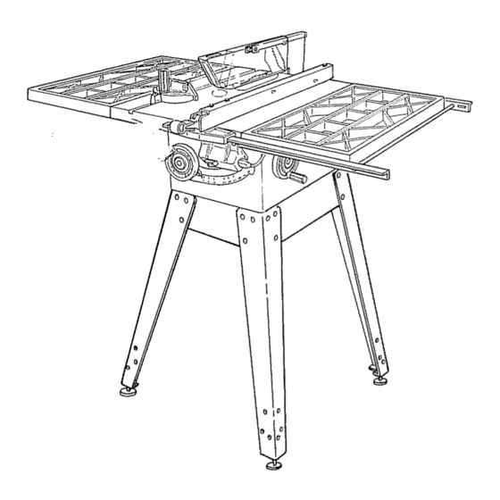
SAW WITH LEGS
TWO CAST IRON
TABLE EXENSIONS
MOTOR AND
QUICK RELEASE
RIP FENCE
i,j_ll j,
_lt_,,_,IH,
!1'! !1"
Serial
Number
Modeland serial numbermay
be found
at the left-hand side of the base
You should
record both model and
serial number in a safe place for future
use
FOR YOUR
SAFETY:
READ ALL
INSTRUCTIONS
CAREFULLY
104NCH TABLE SAW
. assembly
ooperating
, repair parts
Sold by SEARS,
ROEBUCK
AND CO., Chicago,
IL. 60684 U.S.A.
Part No,, SP5415
Printed in USA.
Advertisement
Table of Contents

Related Manuals for Craftsman 113.298760


Summary of Contents for Craftsman 113.298760
- Page 1 s- ss- ol- _Ip 6" Save This Manual For Future Reference o wr_ers manual MODEL NO. 113.298760 SAW WITH LEGS TWO CAST IRON TABLE EXENSIONS MOTOR AND QUICK RELEASE RIP FENCE i,j_ll j, _lt_,,_,IH, !1'! !1" Serial Number Modeland serial numbermay be found at the left-hand side of the base You should...
-
Page 2: Safety Instructions
ON CRAFTSMAN TABLE If within one year from the date of purchase, this Craftsman Table Saw fails due to a defect in material or workmanship, Sears will repair it, free of charge This warranty applies only while this product is in use in the United States. - Page 3 2. Choose the right blade orcutting accessory Any power saw can throw foreign objects into for the material and the type of cutting you the eyes This can cause permanent plan to do damage Wear safety goggles (not glasses) that comply with ANSI Z87..1 (shown on pack- 3 Never use grinding wheels, abrasive cut-off age)..
-
Page 4: Rip Type Cuts
- Nevercut morethan one workpieceat a c Wait for all moving parts to stop time d Check blade, spreader and fence for proper -Never turn your table saw "ON" before alignment before starting, again.. clearingeverythingexceptthe workpiece 8 To avoid throwback of small, cut off pieces: andrelatedsupportdevices off the table. -
Page 5: Terms
additional instructions for CROSS CUT TYPE CUTS While cutting - To avoid blade contact, always hold the miter gauge as shown in the BASIC SAW OPERA- Before starting TIONS - USING THE MITER GAUGE - NEVER use the rip fence when crosscutting An auxiliary wood facing attached to the miter... - Page 6 MOTOR SPECRFtCATDONS AND ELECTROCAL REQUIREMENTS This saw is designed to use a 3450 RPM motor only.. Do If,the outlet you are planning to use for' this saw is of the not use any motor that runs faster than 3450 RPM. It is two prong type DO NOT REMOVE OR ALTER THE wired for operation on 120 volts, 60 Hz.
-
Page 7: Table Of Contents
CONTENTS WARRANTY ................Removing and Installing Sawblade ....... 24 SAFETY iNSTRUCTIONS FOR TABLE SAWS ....Exact-l-Cut ..............24 BASIC SAW OPERATION ..........25 Rip Type Cuts ................Work Helpers ............... 2 5 Cross Cut Type Cuts .............. GLOSSARY OF WOODWORKING TERMS ..... -
Page 8: List Of Loose Parts
® S_ZE © Ao'_ LIST OF LOOSE PARTS Item Part Name Qty. Blade Guard and Spreader....B Rip Fence ........C Owners Manual ......D Cast hon Table Extensions ....Item P_rt Name gty, E Miter Gauge ......... F Rip Fence Guide Bar Rod ....Nut, Heavy Hex Jam 5116-18 .... -
Page 9: Assembly
ASSEMBLY Before mounting the saw on legs, a stand or a bench, the Table Insert and Blade Squareness must be checked at this time.. LOCKWASHER INSTALLING HANDWHEELS 1. Line up FLAT SPOTS on shaft and hardwheei, push handwheel onto shaft. Install screw and 10-32 x 3/4... -
Page 10: Assembling Steel Legs
ASSEMBLING STEEL LEGS From among the loose parts, find the following Hardware: 24 Truss Head Screws, 1/4-20 x 5/8 in, long (top of ASSEMBLE SCREWS THROUGH HOLES screw is rounded) MARKED "X" 24 Lockwashers, 1/4 in., External Type (approx SIDE STIFFENER dia,. - Page 11 , i_ _¸¸" ; ATTACHING AND ASSEMBLING TABLE EXTENSIONS From among the loose parts find the following hardware: (Quantity indicated is for 2 extensions) HARDWARE FOR INSTALLING EXTENSIONS TO SAW TABLE Ref, No, Description Qty. Hex Hd Screw, 5/16-18 x 1-1/4 ..
-
Page 12: Mounting Switch
MOUNTING SWITCH JAM NUT 5/16-18 From among loose parts find the following: 2 Hex Head Screws, 5/16-18 x 3/4 in. long ,@ ,_ iLOCKWASHER 2 Flatwashers (dia. of hole 21/64 in ) • 8TH HOLE 2 External Lockwashers 2 Hex Nuts, 5/16-18 _ _\ FRONT FENCE... - Page 13 8. Holdrodwithonehandandwitha I/2 in,, w rench or pliersstartscrewing onONEofthenutsonlyA TURNORTWO. screwon othernut thesame way. 9, Using TWO1/2 in. wrenchesor pliers tighten bothof the nuts. 10,Slidethe barsso thatscrewsarein the MIDDLE of the slottedholes. 1I. Position rip fence over miter gauge groove, holdinguptherearendwhileengaging frontend with bar lowerfenceontotable, 8 THICKNESSES...
-
Page 14: Aligning Rip Fence
ALIGNING RIP FENCE The fence should slide easily along the bars and always remain in alignment (parallel to sawblade and miter gauge grooves), The alignment is maintained by a spring underneath the fence which bears against the front guide bar To move the fence, loosen the lock handle and grasp the fence with one hand at the front For very close adjustments,... - Page 15 If fence does not slide easily along the bars, the pressure of the spring can be REDUCED 1 Loosen the screws 2, Move spring slightly toward rear of fence tighten screws, WARNING: TO AVOID INJURY FROM JAMS OR SPRING KICKBACK, BE SURE TO PROPERLY ADJUST AND PUSH LOCK LEVER ALL THE WAY DOWN UNTIL THE LEVER RESTS ON THE STOP BEFORE USING THIS RIP FENCE.
-
Page 16: Adjusting Rip Scale Pointer
ADJUSTING RIP SCALE POINTER Turn ELEVATION HANDWHEEL clockwise until blade is up as high as it will go IMPORTANT: BLADE must be SQUARE (90 °) to LOCK HANDLE _-_ TABLE, in order to ALIGN rip fence 2. Position fence on right side of sawbtade so that it touches the sides of the teeth tighten... - Page 17 7,. Slide SPREADER ROD into BLADE GUARD SUPPORT until end of ROD is even with edge of SUPPORT • Tighten Hex Head Screw in support, 8. Attach SPREADER to SPREADER SUPPORT so that the edge of the spreader is even with the edge of the spreader support tighten screws, 9 Raise ANTIKICKBACK...
-
Page 18: Mounting The Motor
16 Make two folds in a small piece (6 x 6 in ) of ordinary NEWSPAPER making three thicknesses The folded paper will be used as a "spacing gauge", 17. Place RIP FENCE on table _... CAREFULLY move it against blade so that it is parallel to the blade, and just TOUCHES tips of saw teeth.., tighten RIP FENCE LOCK LEVER... - Page 19 7 Fromamongthe looseparts, find the following hardware: 4 Carriage Bolts, 5/16-18 x 3/4 in.. long 4 Hex nuts, 5/16-!8 (approx dia.. of hole 5/16 in.) 4 Lockwashers, 5/16 in. External Type (approx dia of hole 5/16 in) I Cast Iron Motor Pulley The motor base is installed in the cradle for ship- ment.
-
Page 20: Installing Belt Guard
14. Lower the blade ..install belt on saw pulley and motor pulley,, 15. Sight along edges of both pulleys and move motor pulley so that belt is parallel to the edges of both pulleys ..tighten the set screw in the motor' pulley° PINS 16, IMPORTANT: Measure the distance from end of... -
Page 21: Plugging In Motor
OPENING Install three CLIPS (furnished with guard) 90 ° apart starting with one clito at the end of the guard as shown., LONG END of clip facing BELT GUARD AWAY from you LONG END 5 Reinstall motor pulley the same way it was when you aligned the belt 6, Place belt on SAW PULLEY ., insert end of belt... -
Page 22: Getting To Know Your Saw
GETTBNG TO KNOW YOUR SAW SAWBLADE BLADE GUARD TABLE INSERT EXACT-I-CUT ANTIK[CKBACK PAWLS MITER GAUGE RIP FENCE HOLES ATTACHING FACING TILT LOCK HANDLE (UNDERNEATH TABLE) ELEVATION HANDWHEEL TILT HANDWHEEL ON-OFF SWITCH ON-OFF SWITCH CAUTION: Before turning switch on, make sure the blade guard is correctly installed and operating properly,... -
Page 23: Miter Gauge
ELEVATION HANDWHEEL ..e levates or lowers If necessary, the miter gauge head can then be the blade.. Turn clockwise to elevate ..counter- swiveled slightly to compensate and then locked.. clockwise to lower Slots are provided in the miter gauge for attach- ing an AUXILIARY FACING to make it easier to TILT HANDWHEEL... -
Page 24: Removing And Installing Sawblade
NEVER OPERATE WITHOUT PROPER INSERT IN PLACE USE OF THE SAW BLADE INSERT WHEN SAWING . . • USE THE COMBINATION DADO MOLDING INSERT WHEN DADOING OR MOLDING.. REMOVING AND INSTALLING SAWBLADE, WARNING: For your own safety, turn switch "OFF" and remove plug from power source... -
Page 25: Basic Saw Operation
BASIC SAW OPERATION WORK HELPERS Before cutting any wood on your saw, study all of the SLIGHTLY LESS THAN "Basic Saw Operations" THICKNESS OF WORKPIECE Notice that in order to make some of the cuts, it is UP TO 3/8" necessary to use certain devices "Work Helpers"... -
Page 26: Safety Instuctions For Basic Saw Operatiori
3/4 PLYWOOD AUXILIARY FENCEP, NORK SUPPORT 3-1/2"" Make one using a piece of 3/8 in. and 3/4 in.. plywood Fasten together with glue and wood screws. 1-1/4 NOTE: Since the Push Block is used with the Auxiliary Fence, the 4-3/4 in. dimensions must be held identical on both the pieces, THIS FACE AND EDGE MUST BE... - Page 27 Any power saw can throw foreign objects into 4 Choose and inspect your cutting tool care- the eyes This can cause permanent fully damage Wear safety goggles (not glasses) a To avoid cutting tool,failure and thrown that comply with ANSi Z87,1 (shown on pack- shrapnel (broken pieces of blade),...
- Page 28 1 Before actually cutting with the saw, watch - Never confine the piece being cut off That while it runs for a short while, If it makes an is, the piece NOT against the fence, miter unfamiliar noise or vibrates excessively, stop gauge...
-
Page 29: Using The Miter Gauge
USING MITER GAUGE The MITER GAUGE is used when CROSSCUTTING, - An auxiliary wood facing attached to the miter MITER CUTTING, BEVEL CUTTING, COMPOUND gauge can help prevent workpiece twisting throwbacks Attach it to the holes provided MITER CUTTING, DADOING andwhen RABBETTING Make the facing long enough and big enough to AND MOLDING across the end ol a narrow workpiece. -
Page 30: Repetitive Cutting
REPETITIVE CUTTING REPETITIVE CUTTING is known as cutting quantity of pieces the same length without having to mark each piece, t Use the Stop Rods (optional accessory) only for cutting duplicate pieces 6 in, long and longer 2. Follow all safety precautions and operational instructions... -
Page 31: Bevel Crosscutting
BEVEL CROSSCUTTING BEVEL CROSSCUTTfNG is the same as crosscutting except that the wood is also cut at an angle other than 90 ° with the flat side of the wood Adjust the blade to the desired angle. Use the Miter Gauge in the groove to the RIGHT of the blade It cannot be used in the groove to the... -
Page 32: Ripping
RiPPiNG Ripping A cutting operation along J.helength of the workpiece.. ALWAYS SUPPORT LONG WORKPIECES Position the fence to the desired WIDTH OF RiP and lock in place Before starting to rip, be sure A Rip Fence is parallel to sawblade B Spreader is properly aligned with sawblade C Antikickback... - Page 33 When "WIDTH OF RIP" is 6 in.. and WIDER use your RIGHT Hand to feed the workpiece until it is clear of the table., Use LEFT hand ONLY to guide the workpiece ..do not FEED the workpiece with the left hand. When "WIDTH OF RIP"...
- Page 34 Feedthe workpieceby handalongthe AUXILIARY FENCE until the endis approx.1 in,,pastthe front edgeof the table,Continueto feedusingthe PUSH BLOCK, Holdtheworkpiece in positionandinstallthePUSH BLOCK by sliding it on top of the AUXILIARY FENCE/WORK S UPPORT (ThisMayRaiseGuard) BAFFLE NarrowstripsthickerthantheAuxiliaryFence/Work Supportmayenterthe guardandstrikethe baffle. CAREFULLY raiseguard onlyenoughto clear' t he workpieceUsePUSHBLOCK to completecut...
-
Page 35: Resawing
RESAWING RESAWING is known as ripping a piece of wood through its thickness. Do not attempt to resaw BOWED or WARPED material. NOTE: To RESAW a piece of wood wider than 3-3/8 inch. it will be necessary to remove the blade guard ... and use the AUXILIARY FENCE/WORK SUPPORT... -
Page 36: Rabbeting
RABBETING RABBETING is known as cutting out a section of the _- FIRST CUT corner of a piece of material, across an end or along RABBET an edge, I SECOND To make a RABBET requires cuts which do not go al! the way through the material Therefore... -
Page 37: Molding Cutting
MOLDING CUTTING Instructions tor operating the Molding Head are con- When using the molding head, it will be necessary to tained in a booklet furnished with the Molding Head. remove the Blade Guard and Spreader USE CA[J- TION. USE MITER GAUGE, FENCE, FEATHER-... -
Page 38: Heeling Adjustment Or Parallelism Of Sawblade To Miter Gauge Groove
HEELING ADJUSTMENT PARALLELISM OF SAWBLADE TO NtlTER GAUGE GROOVE While cutting, the material must move in a straight line PARALLEL to the SAWBLADE ..therefore both the miter gauge GROOVE and the RIP FENCE must be PARALLEL to the SAWBLADE.. If the sawbtade IS NOT parallel to the miter gauge groove, the blade will bind at one end of the cut... - Page 39 EDGE OF TRUNNION 8 Using a wood block and mallet as shown, move rear trunnion to right or left as required to realign the blade.. If necessary, shift front trunnion similar manner; but do NOT move front trunnion WOOD BLOCK unless necessary Recheck the alignment...
- Page 40 If blade is SQUARE to table; POINTER A. Check pointer tF POINTER DOES NOT point to the"0" mark on the bevel scale; A Remove Elevation Handwheel, SCALE ADJUSTING SCREW B Loosen screw and adjust pointer . _ , using medium screwdriver, POINTER "0"...
-
Page 41: Tilt Mechanism
Frequently blow out any dust that may accumulate inside the saw cabinet and the motor., Frequently clean your cutting tools with Craftsman Gum and Pitch Remover.. A coat of automobile-type wax applied to the table will help to keep the surface clean and allow work- pieces to slide more freely,, 2. -
Page 42: Accessories
Titt screw threads and pivot nuL (First Clean with Craftsman Gum & Pitch Rernover..) 2 Elevation screw threads and pivot (First Clean with Craftsman Gum & Pitch Remover.) 3. Cradle bearing points.. 4. Bearing points in guard assembly, miter gauge and rip fence. BEARING POINTS... -
Page 43: Troubleshooting
TROUBLE SHOOTUNG WARNING: For your own safety, turn switch "OFF" and always remove plug from power source outlet before trouble shooting. TROUBLE SHOOTING -- GENERAL TROUBLE PROBABLE CAUSE REMEDY I. Discard Blade and use a different blade_, Excessive vibration. 1. Blade out of balance, I, See "Adjustments"... - Page 44 TROUBLE SHOOTING -- MOTOR (Continued) TROUBLE PROBABLE CAUSE REMEDY ......,,,, ,,, Motor starts s|owly Low voltage 1. Request voltage check from powe_company 2. Windings burned out or fails to come up 2,, Have motor repaired or replaced to full speed. or open 3,, Starting switch not 3.
-
Page 45: Repair Parts
FIGURE 1 - RIP FENCE ASSEMBLY 62952 Part Part Description Description 62942 Handle 62529 Lock, Rear Fence 62945 Shoe 62531 Roller, Rear Fence 62775 indicator 62944 Rod, Fence Lock 9404336 62533 Screw, Pan Cross Type "T" Spring, Head Alignment No, 4-40 x 1/4 (Includes Key #16) 62941 STD551210... - Page 46 PARTS LIST FOR CRAFTSMAN 10 INCH TABLE SAW MODEL NO. 113.298760 Figure3...
- Page 47 PARTS LIST FOR CRAFTSMAN 10 INCH TABLE SAW MODEL NO. 113,298760 Always order by Part Number - not by Key Number. FIGURE 3 PARTS LIST Part Part Description Description Hi u uiH,l,/u/llt .... lullul,lll hi,J/u/u,,,,,, *Lockwasher, External No. 10 STD551210...
- Page 48 PARTS LIST FOR CRAFTSMAN 10 INCH TABLE MODEL NO. 113.298760 ® 35 34 33 32 Figure...
- Page 49 PARTS LIST FOR CRAFTSMAN 10 INCH TABLE MODEL NO. 11&298760 FIGURE 4 PARTS LIST Part Part Description Descr!ption ......li, lll,ll u nHl,ullll 60i'78 Washer, Spring Support, Spreader 62587 STD302111 O-ring 60204 Screw, Thumb 5/16-18 x 1 62697 Screw, Lift...
- Page 50 PARTS LIST FOR CRAFTSMAN 10 INCH TABLE MODEL NO. 113.298760 11 1 FIGURE 5 - MITER GAUGE ASSEMBLY FIGURE 6 - 62579 GUARD ASSEMBLY Part Part Description Description 62579 Guard Assembly, Saw 9-29929 +Gauge Assembly, Miter 60297 Nut, Push 62693...
- Page 51 PARTS LIST FOR CRAFTSMAN 10 INCH TABLE MODEL NO. 113.298760 FIGURE 8 - TABLE EXTENSIONS FIGURE 7 - LEGS Part Part Description Description 62947 Extension, Table 'I2 x 27 60314 Screw, Serrated Truss 1/4-20 x 5/8 STD523112 * Screw, Hex Hd, 5t16-18 x...
- Page 52 _.lllllll ,i,iillllll ,ll,,,i L,I,Iii, 10 fNCH TABLE SAW SERVICE Nowthat you have purchased your 10-inch table saw, should a need ever exist for repair parts or service, simply contact any Sears Service Center and most Sears, Roebuck and Co stores. Be sure to provide all pertinent facts when you call or visit.