Advertisement
Table of Contents
- 1 Operation
- 2 Maintenance and Storage
- 3 Maintenance
- 4 Tools Required for Assembly
- 5 Check Tire Pressure
- 6 Handle Height
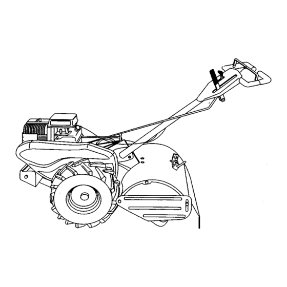
- 7 Know Your Tiller
- 8 To Start Engine
- 9 Tine Shear Pins
- 10 General Recommendations
- 11 Lubrication Chart
- 12 Air Cleaner
- 13 Spark Plug
- 14 Tine Replacement
- 15 Engine Fuel System
- 16 Tine Assembly
- Download this manual
Owner's Manual
CRRFTSMRN
5.0 HP
17 INCH TINE WIDTH
REAR TINE WITH COUNTER
ROTATING TINES
TILLER
Model No.
917.293203
• Safety
• Assembly
• Operation
• Maintenance
• Espa_ol
• Repair Parts
CAUTION:
Read and follow all Safety
Rules and instructions before
operating this equipment.
For answers to your questions
about this product, Call:
1-800-659-5917
Sears Craftsman Help Line
5 am- 5 pro, Mort* Sat
Sears, Roebuck and Co., Hoffman Estates, II 60179
Visit our Craftsman website:www,sears.com/craftsman
Advertisement
Table of Contents

Related Manuals for Craftsman 917.293203


Summary of Contents for Craftsman 917.293203
- Page 1 For answers to your questions about this product, Call: Read and follow all Safety 1-800-659-5917 Rules and instructions before Sears Craftsman Help Line operating this equipment. 5 am- 5 pro, Mort* Sat Sears, Roebuck and Co., Hoffman Estates, II 60179 Visit our Craftsman website:www,sears.com/craftsman...
- Page 2 • if this Craftsman Tiller is used for commercial or rental purposes, this Warranty applies for only thirty (30) days from the date of purchase.
-
Page 3: Operation
MAINTENANCE AND STORAGE OPERATION • Do not put hands or feet near or under • Keep machine, attachments, rotatingparts. accessories in safe working condition. • Exercise extreme caution when operating on or crossing gravel drives, • Check shear pins, engine mounting walks, or roads. -
Page 4: Maintenance
PRODUCT SPECIFICAT!ONS MAINTENANCE AGREEMENT GASOLINE 3 QTS A Sears Maintenance Agreement is available on this product. Contact UNLEADED 3APACITY: your nearest Sears store for details, REGULAR CUSTOMER DIL(API-SF/SG/SH): SAE 30 RESPONSIBILITIES CAPACITY: 20 OZ.) (ABOVE 32°F) • Read and observe the safety rules. SAE 5W-30 •... -
Page 5: Tools Required For Assembly
Your new tiller has been assembled at the factory with exception of those parts left unassembled for shipping purposes. To ensure safe and proper operation of your tiller all parts and hardware you assemble must be tightened securely. Use the correct tools as necessary to insure proper tightness. - Page 6 UNPACKING CARTON Handle Assembly "UP" Position% ACAUTION: Be careful of exposed staples when handling or disposing of Tighten handle lock cartoning material. lever to hold IMPORTANT:When unpacking and assembling tiller, be careful not to stretch or kink cables. Loosen Handle Lock •...
-
Page 7: Check Tire Pressure
REMOVE TILLER FROM CRATE INSERT CABLE CLIP • Adjust handle assemby to lowest • Insert plastic cable clip into hole on the back of handle column. Push cables position. Be sure hex bolt is tightened securely. into clip. • Make sure shift lever indicator is in =N" Handle Column (neutral) position. -
Page 8: Know Your Tiller
These symbols may appear on your Tiller or in literature supplied with the product, Leam and understand their meeting. KNOW YOUR TILLER READ THIS OWNER'S MANUALAND SAFETY RULES BEFORE OPERATING YOUR TILLER. Compare the Illustrations with your tiller to familiarize with the location of various controls... - Page 9 The operation of any tiller can result in foreign objects thrown into the eyes, whichcan result in severe eye damage. Always wear safety glasses or eye shields before starting your tiller and while tilling. We recommend a wide vision safety mask over spectacles or standard safety glasses. HOW TO USE YOUR TILLER HARD TO SHIFT GEARS Know how to operate all controls before...
- Page 10 TURNING CHECK ENGINEOILLEVEL • Release the drive control barl • The engine in your unit has been • Move throttle control to "SLOW" shipped, from the factory, alreadyfilled position, with SAE 30 summer weight oil, • • Place shift lever indicator in UF" •...
-
Page 11: To Start Engine
TILLING HINTS Do not overfill. Wipe off any spilled oil or fuel. Do not store, spill or use gasoline _I,CAUTION: Until you are accustomed to near an open flame. handling your tiller, start actual field use TO START ENGINE with throttle in slow position. •... -
Page 12: Tine Shear Pins
CULTIVATING ADJUST WHEELS CULTIVATING Cultivating is destroying the weeds between rows to prevent them from • Place blocks under right hand side of robbing nourishment and moisture from tiller and remove hairpin clip and clevis the plants. At the same time, breaking up pin from right hand wheel. -
Page 13: General Recommendations
SCHEDULE MAINTENANCE _//J_/ F,LL,NO,TOS ,/d/ Check Engine Oil Level Change Engine Oil 1_1,2 _l PivotPokers II/' Inspect Spark An'ester / Muffler Inspect Air Screen Clean or Replace Air Cleaner Cartridge Clean Engine Cylinder Fins Replace Spark Plug RH Gear Case Grease Fitting (1oz.) 1 - Change more oRen when operlaing under a heavy load or k_high ambient temperatut'e6, 2. -
Page 14: Air Cleaner
• Refill engine with oil. See "CHECK ACAUTION: Disconnect spark plug wire ENGINE OIL LEVEL" in the Operation before pedorming any maintenanc e section of this manual. (except carburetor adjustment) to prevent accidental starting of engine. Prevent firesf Keep the engine free of grass, leaves, spilled oil, or fuel. -
Page 15: Spark Plug
SPARK PLUG Muffler. rRns Replace spark plugs at the beginning of each tilling season or after every 50 hours of use, whichever comes first. Spark plug type and gap setting are shown in "PRODUCT SPECIFICATIONS". TRANSMISSION Once a season, lubricate the right hand gear case grease fitting with 1 oz. - Page 16 TO REPLACE GROUND DRIVE TO REMOVE BELT GUARD BELT NOTE: For ease of removal, remove • Remove belt guard as described in "TO hairpin clip and clevis pin from left wheel. REMOVE BELT GUARD". Pull wheel out from tiller about 1 inch. •...
-
Page 17: Tine Replacement
TINE REPLACEMENT this wom needs to be replaced. • To maintain the superb tilling perfor- ACAUTION: "nnes are sharp. Wear mance of this machine the tines should gloves or other protection when handling be checked for sharpness, wear, and tines. bending, particularly the tines which are A badly worn tine causes your tiller to next to the transmission. - Page 18 ENGINE FINAL SE'R'ING Maintenance, r epair,or replacementof • Start engine and allow to warm for five minutes. the emissioncontroldevicesand sys- tems,which • With throttle control lever in =SLOW" are being done at the position. customers expense, may be performed IDLE RPM ADJUSTMENT by any non-roed engine repair establish- ment or individual.
-
Page 19: Engine Fuel System
NOTE: Fuel stabilizer is an acceptable Immediately prepare your tiller for storage at the end of the season or if the unit will alternative in minimizing the formation of fuel gum deposits during storage. Add not be used for 30 days or more. stabilizer to gasoline in fuel tank or _CAUTION: Never store the tiller with... - Page 20 CORRECTION PROBLEM CAUSE 1. Out of fuel. 1. Fill fuel tank. Will not start 2. See "TO START ENGINE" in 2. Engine not "CHOKED" the Operation section. properly. 3. Wait several minutes before 3. Engine flooded. attempting to start. 4. Clean or replace aircleaner 4.
- Page 21 PROBLEM CORRECTION CAUSE Engine 1. Low oil level/dirty oil. 1. Check oil level/change oil. overheats 2. Dirty engine air screen. 2. Clean engine air screen. 3. Dirty engine. 3. Clean cylinder fins, air screen, muffler area. 4. Remove and clean muffler. 4.
- Page 22 TILLER - - MODEL NUMBER 917.293203 HANDLES PART PART DESCRIPTION DESCRIPTION Washer 13/32 x'l x 11 Ga. 127012X ContmlThrottle 19 19131611 Lever, Lock, Handle 141406 Grip, Handle 20 109228X 110673X Grommet, Handle 21 150258 Handle, Assemble Clip, Nyl BIk Cable 127254X Bar, Drive ControlAssembly 165197...
- Page 23 TILLER - - MODEL NUMBER 917.293203 MAINFRAME, L EFTSIDE PART DESCRIPTION SrD541431 *Nut, Kepa, Flange 5/16-18 S'[D551137 "Washer, Lock 3/8 PART STD541037 "Nut, Hex 3/8-16 DESCRIPTION 170127 Sh_d, Inner Bert Guard Rt *Clip, Hairpin 154734 Screw Shift Lever 25 STD624003 Guard, Belt 110111X Lever, Shltt...
- Page 24 TILLER - - MODEL NUMBER 917.293203 MAINFRAME, RIGHT SIDE KEY PART PART DESCRIPTION DESCRIPTION 14 STD541431 102332X Bracket, R elnforcrnent *Nut, Keps 5/16-18 15 ..74760524 Bolt, Hex 5/16-18 x 1-1r2 Engine, (See Breakdown) 102173)( Btigg_ & Stratton Model No. Counter Weight, R.R.
- Page 25 TILLER - - MODEL NUMBER 917,293203 TRANSMISSION 51 S4 KEY PART KEY PART DESCRIPTION DESCRIPTION 1 170337 Transmission Aseambty (Includes 106388X Spacer 0.70 x 1.00 x 1.150 KeyNos. 2-54) 102121X Sprocket and Gear Assembly 165729 Gearcase, LH. w/Bearing 102112X Shaft, Reduction (2nd) (Includes Key No.
- Page 26 TILLER - - MODEL NUMBER 917.293203 TINE SHIELD PART PART DESCRIPTION DESCRIPTION 73900500 "Nut, Hex 3/8-16 Nut, Lock Hex Flange 5/16-18 20 STD541037 161415X558 Shield, Side, Outer L H. 102156X Stake, Depth 8393,1 Bolt, Hex 3/8-16 x 2 Pin, Stake, Depth 22 74930632 12000036 Ring, Klip...
-
Page 27: Tine Assembly
TILLER - ' MODEL NUMBER 917.293203 TINE ASSEMBLY PART PART DESCRIPTION DESCRIPTION 4459J Tine, Outer, L.H. 4460J Tine, Outer, R.H. 132673 Pin,Shear 10 132728 Assembly, Hub end Plate, R.H. 6554J Tine, Inner, L.PI. 11 6555J Tine, inner, R.H. STD624008 Retainer, Spdng 132727 * STANDARD HARDWARE - - PURCHASE Assembly, Hub end Prate+L.H. - Page 28 Decal, Caution, Drive Control 120431X Decal, Hand Placement 102180X Decal, Shift Indicator 110719X Decal, Operation and Lubrication 165268 Decal, Craftsman 120075X Decal, Warning, Rotating Tines 10 1'57984 Decal, Counter Rot. Tine 11 165278 Decal, 5 HP 12 162215 Decal, Tine Shield Wing Dora...
- Page 29 TILLER - - MODEL NUMBER 917.293203 ENGINE, BRIGGS & STRATI"ON - - MODEL NUMBER 137202, TYPE NO. 1125-E1 _500 INSTRUCTION MANUAL.
- Page 30 TILLER - - MODEL NUMBER 917.293203 ENGINE,BRIGGS& STRATTON - - MODELNUMBER137202,TYPENO. 1125-E1...
- Page 31 TILLER - - MOOEL NUMBER 917.293203 ENGINE, BRIGGS & STRA'rTON - - MODEL NUMBER 137202, TYPE NO. 1125-E1 10.SVA_EO_._U._S_,_...
- Page 32 TILLER -- MODEL NUMBER 917.293203 ENGINE,BRIGGS& STRATTON - - MODELNUMBER137202, T YPENO.1125-E1 KEY PART KEY PART NO. NO. DESCRIPTION NO. NO. DESCRIPTION 497144 Cylinder Assembly 260552 Spring, IntakeValve 399268 Bushing,Cylinder 26478 Spring, ExhaustValve 299819 * Seal, Oil 222443 Guard, Flywheel 214040 Head, Cylinder 93312...
- Page 33 TILLER - - MODEL NUMBER 917.293203 ENGINE, B RIGGS& STRATTON - - MODELNUMBER137202,TYPENO.1125-E1 KEY PART KEY PART NO. NO. DESCRIPTION NO, NO. DESCRiPTiON 280720 BellCrank 231079 Bushing,GovernorCrank 231520 Screw,Shoulder 94907 Bolt, GovernorLever 262279 Red, Speed Control 231978 Nut, Hex 209 262284 Spdng,Governor 692696 Starter Assembly,Rewind...
- Page 36 For in-home major brand repair service: Call 24 hours a day, 7 days a week 1-800-4-MY-HOME s" (1-800-469-4663) Para pedir servic|o de reparaci6n a domicilio 1-800-676-5811 In Canada for all your service and parts needs call Au Canada pour tout le service ou les pi_ces 1-800-665-4455 For the repair or replacement parts you need:...