Table of Contents
Advertisement
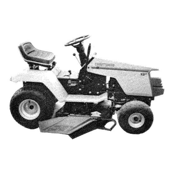
OWNER'S
MANUAL
MODEL NO.
917.254520
Caution:
Read and follow
all Safety Rules
and instructions
Before Operating
This Equipment
£RRFTSMRN ®
12.
IC
ELECTRIC START
_"
DECK
5
TRANSAXLE
LAWN TRACTOR
•
Assembly
,
Operation
= Maintenance
•
Service and Adjustment
•
Repair Parts
Sears, Roebuck and Co., Chicago, IL 60684 UoSoA.
Advertisement
Table of Contents

Related Manuals for Craftsman 917.254520


Summary of Contents for Craftsman 917.254520
- Page 1 OWNER'S MANUAL MODEL NO. 917.254520 £RRFTSMRN ® Caution: Read and follow all Safety Rules ELECTRIC START and instructions Before Operating _" DECK This Equipment TRANSAXLE LAWN TRACTOR • Assembly Operation = Maintenance • Service and Adjustment • Repair Parts Sears, Roebuck and Co., Chicago, IL 60684 UoSoA.
-
Page 2: Brake
CAUTION: LOOK FOR THIS WORD TO POINT OUT LOOK FOR THiS SYMBOL TO POINT iMPORTANT EQUIPMENT PRECAUTIONS. iMPORTANT SAFETY PRECAU- TIONS. iT MEANS _ ATTENTION! NOTE: LOOK FOR THIS WORD TO POINT OUT IM- COME ALERT. I YOUR SAFETY JS iN- ... - Page 3 CONGRATULATIONS on your purchase of a Sears Lawn Tractor. It has been designed, engineered manufactured to give you the best possible dependability and performance. Should you experience any problem you cannot easily remedy, please contact your nearest Sears Service Department. We have competent, well- DATE OFPURCHASE...
-
Page 4: Table Of Contents
iNDEX Filter: Options: Adjustments: Air Cleaner ......16 Attachments ......46 Brake ........Fuel ........Spark Arrester ....2,32 Carburetor ......Fuel: Mower Drive Belt ....22 Type ........Mower Sto rage ........Parking Brake ........ 9 Front-To-Rear ....23 Fuse .......... - Page 5 ASSEMBLY To assemble tractor you wifl need: 12) 7/16" wrenches Tire Pressure Gauge 11) 1/2" wrench Screwdriver (2) 9/16" wrenches UtiRy Knife (1) 3/4" wrench 5/16" Wrench Take all of the items out of the box. The box contains the _tems shown beiowo Open the parts bag and check the contents (see page 6).
- Page 6 ..ASSEMBLY ASSEMBLY PARTS BAG CONTENTS SHOWN FULL SiZE LOCATION BATTERY (2) Wing Nut 1/4-20 © BATTERY (2) Hex Bolt 1/4-20 x 3/4 TERMINALS (2) Lock Washer (2) Washer 9/32 x 5/8 x !6 Ga. (2) Hex Nut 1/4-20 SEAT (1) Adjustment Bolt (1) Lock Washer 1/2 (1) Washer...
- Page 7 ASSEMBLY !. Prepare B_tery WEAR EYE AND FACE SHIELD, CUT AWAY ViEW BATTERY WASH HANDS OR CLOTHING IMMEDI- ATELY iF ACCIDENTALLY iN CONTACT WiTH BATTERY ACID. SMOKE. FUMES FROM CHARGED BATTERY ACID ARE EX- PLOSIVE. READ THE iNSTRUCTiONS iNCLUDED WiTH THE BATTERY VENT CAPS iN THE BAG OF PARTS.
- Page 8 ASSEMBLY 3. Instal| Seat SEAT Remove cardboard from seat pan. Place seat on seat pan. S_rew adjustment bolt, k)ck SEAT PAN SHOULDER shoulder bolt and washers found in bag of parts BOLT (shown full size on page 6). Tighten shoulder boif using a 1/2" wrench. NOTE: THE SHOULDER BOLT WILL BE LOOSE IN THE SEAT PAN SLOT.
- Page 9 ASSEMBLY Lift seat (Fig. 3). Connect BLACK ground cable to negative (-) bat- Lower battery into fenderwell with battery terminals terminal with remaining hex bolt, flat washer, washer and hex nut (shown full size on pg. 6) toward front of tractor (Fig. 4). Make sure battery found in bag of parts.
- Page 10 OPERATION 1. Stopping Your Tractor AIR SCREEN NOTE: REMOVE KEY WHEN LEAVING TRACTOR PREVENT UNAUTHORIZED USE: OIL FILLER FUEL FILLER CAP/DIPSTICK Push clutch-brake pedal intofull "BRAKE" position. Keep your foot on pedal (Fig. 7). Place attachment clutch lever in "DISENGAGED" position, Move gearshift lever to "NEUTRAL"...
- Page 11 OPERATION 3. StarUng the Engine ATTACHMENT CLUTCH Move throttle control lever (Fig. 7) past "FAST" to LEVER "ENGAGED" the "CHOKE" position. POSiTiON LiFT LEVER FuUy depress clutch/brake pedal. ATTACHMENT CLUTCH LIFT LEVER "HIGHEST" Turn ignition key to "START" and release key as LEVER "DISENGAGED"...
- Page 12 ..OPERATION Mower should be adjusted properly front to back and side to side for good mowing performance. Re- fer to REPAIR AND ADJUSTMENT section (page 22). Use the runner on the R.H. side as a guide; the blade cuts approximately an inch (2.54 cm) outside the runner (Fig.
- Page 13 MAINTENANCE To keep yourtractor running better and longer, perform necessary setvioe using the follow= ANY ADJUSTMENTS, iNSPEC- ing maintenance schedule: TiON OR MAINTENANCE: 1. PUSH TRACTOR CLUTCH/BRAKE WiTH EVERY MOWING PEDAL COMPLETELY iNTO "BRAKE" POSITION. Make sure all nuts on bomtsare tight and cotter pins and retainer springs are secure.
- Page 14 1, Brake Adju_ment D_DA|D "--'-""" Th 0, octor w,.oo ndjo0tab brow0 sy0tom mounted on the right side of the transax_e (F_o 10). _WITHPARKING RAKE ENGAGED) DI_HEST GEAR, THEN Depress clutch_brake pedaJ and engage parking brake. Measure distance between brake operating arm NUT"A"...
- Page 15 proper balance before reinstaliation on mower. An unbalanced or bent blade will cause excessive vi- bration when running, and eventual damage to mower or engine. Replace bent or damaqed blades. To check blade balance, drive a nail into a beam or waft.
- Page 16 ..ANol| f TM hlT ..oil drain plug to drain e ine oil ....v v,_,,--=w, h,m _-- plug securely before fitling with fresh oil Add oi! through the oil filler cap/dipstick (F_g. 15). SCREEN OiL FILLER FUEL CAP CAP/DIPST_CK RECOMMENDED SAE VISCOSaTY GRADES °F °20 °...
- Page 17 RE PAiR AN DADJ USTM ENT $. Cit_ck Muffter inspect and reptace damaged muffler and/or deflector as it BOLTS BLOWER HOUSING ¢outd create a fire hazard and/or damage, 10. Lubricate Pivot Points Place several drops of SAE 30 oil at points where metal parts move against each ether.
- Page 18 REPAIRANDADJUSTMENT (DLE STOP Loosen clamp screw (Fig. 20). Adjust throttle cable until holes "A" are aligned in governor control ptate and side plate. Tighten damp screw. !3. Catbureter Adjustment With engine offtum high speed mixture screwclock- NOTE: THE SCREW SEAT BE DAMAGED TURNING iT TOO FAR CLOCKWISE Turn idle mixture screw clockwise...
- Page 19 REPAIR AND ADJUSTMENT BELT 16. _n Drive _k Removal GUIDE The tractor drive her may be repaacedwithout t_ls. Park the TRANSAXLE tractcr on level area. Engage parking brake. NOTE: A BELT INSTALLATION DECAL IS UNDER LEFT FOOTREST. Ren_ve mower. (See page 21). Remove two retainer springs...
- Page 20 RE PAIR,AND.ADJUSTMENT 18o Hood Remov_J GRASP HERE HOOD DASH HOOD Grasp hood at edge next to dash and open hood to SPRING fu_i up position (Fig. 25). Disconnect headlight connection (Fig. 28). Co Carefully remove hood springs from hinge brack- ets (Fig, 25).
-
Page 21: Mower Drive Belt
..REPAiR AND A DJU STM 2o. Mower R_rnovai ATTACHMENT LIFT LEVER LEVER CLUTCH LEVER PLUNGER "HIGHEST" Remove mower belt per instructions under "Mower "DISENGAGED" POSITION Drive Belt Removal" through step (c). POSITION Remove retainer spring from clutch red; pull clutch rod out of clutch bracket. - Page 22 22. Mower Drive Belt Removal NOTE: MOWER BELT INSTALLAT!ON DECAL LOC- ATED ON MOWER HOUSING. REPLACE ONLY WITH THE BELTS SPECiFiED IN THiS MANUAL. Place attachment clutch lever in "Disengaged" posi- tion (Fig.30). Move Attachment liftlever (Fig. 30) forward to lower COTTER mower to its lowest position.
- Page 23 NOTE:ONEROTATION OF ADJUSTMENT N UTSIS EQUIVALENT TO APPROXIMATELY 3/16"(4.75 REAR ram) HEIGHT CHANGE. SUSPENSION f. Besureal!nutsaresecurely t ightened. g. Replace c over. FRONT-TO-REAR M OWER ADJUSTMENT To obtain the best cutting resu Its, you r mower hous- BOTTOM ing should be adjusted so the front and rear flange OF CURL distance "D"...
- Page 24 LUBRICATION CHART FRONT WHEEL Q BEARING FRONT BEARING ENGINE MOWER CLUTCH PIVOT Q SAE 30 MOTOR OIL GENERAL PURPOSE GREASE REFER TO PAGE 16 FOR ENGINE OIL SPECIFICATIONS...
- Page 25 TROUBLESHOOTING PROBLEM CAUSE/REMEDY WiLL NOT START Push Clutch/Brake Pedal into Brake position Move Attachment Clutch Lever to "Disengaged" position Fii{ Tank with Gasoline. Check Fuel Line and Carburetor (clean if necessary). Replace Fuel Fiitero Use Fresh Fuel Check Fuse for fault and replace Recharge or replace Battery Check Wiring _"...
-
Page 26: Mower Front-To-Rear
TROUBLESHOOTING ..NO LIGHTS Check Fuse, Switch and Wire Connections. Replace Headlight Bulbs Replace Switch WON'T CHARGE Check Fuse for fault and replace _" Replace Battery Replace Regulator t1" Replace Alternator ENGINE WiLL NOT SHUT DOWN WHEN OPERATOR LEAVES SEAT NOTE: This tractor is equipped with an operator presence sensing system. - Page 27 12 HP 38" RiDiNG LAWN TRACTOR-- MODEL NUMBER 917-2545201 ......SCHEMATIC ........................BLACK ollllo INTERLOCKSWITCHES ATTMENT CLUTCH (CLUTCH OFF)WHFE WHFE CLUTCH/BRAKE (PEDALUP) SOLENOID SEAT SWITCH (NOT OCCUPIED) FUSE IGNITION ?___) SWFr_U 30 AMP UNIT IGNITION SPARKPLUG BLACK IGNITIONSWITCH POSITION CIRCUIT DDDE CHARGING COIL...
- Page 28 REPAIR PARTS 12 HP 38" RiDiNG LAWN TRACTOR - - MODEL NUMBER 917.254520 ELECTRICAL...
- Page 29 REPAIR PARTS 12 HP 38 °° RIDING LAWN TRACTOR - - MODEL NUMBER 917.254520 ELECTRICAL PART DESCRiPTiON PART DESCRIPTION N O . 7662J Butb, Light 72240460 Bolt - Rd. Hd. Sq. Nk. - 20 x 124108X Harness, Light Socket 7-1/2 ! 24904X Harness, Wiring...
- Page 30 REPAIR PARTS 12 HP 38" RtDING LAWN TRACTOR - - MODEL NUMBER 917.254520 CHASSIS AND ENCLOSURES...
- Page 31 124294X Pan - Seat 17490616 Screw. Hex Washer Thd RoH_ng 125880X Decal Fender 3/816 × ! t24492X Decal, Grill Craftsman ! 055 ! 3X Bracket-P_vot. Seat 4900J Decai. C_utch!Breke 105529X Bolt, Shou!der, 105809X Decal, Chassis, 5 Speed, 38" 73680500 Crownlock...
- Page 32 REPAIR PARTS 12 HP 38" RIDING LAWN TRACTOR - o MODEL NUMBER 917.254520 DRIVE OPTIONAL £OUIPM£NT Spark Arrester...
- Page 33 12Ga STD522510 *Bott, Hex Fin 1/4x20UNCxl t05730X Keeper, Belt, Engine 13290300 Oil Drain P_ug 109070x Retainer Belt 126685X Decal0 !2 HP, Craftsman, Engine 447OJ Spacer 123674X ldter, Fiat _STANDARD HARDWARE--PURCHASE LOCALLY NO]E: AI_ component dimensions given in U.S. inches.
- Page 34 ..REPAJR,_PART_ 12 PiP 38" RIDING LAWN TRACTOR - MODEL NUMBER 917.254520 STEERJNG ASSEMBLY 14" 27 30 56 55...
- Page 35 REPAIR PART8 12 HP 38" RIDING LAWN TRACTOR ° ° MODEL NgMIBER 917.254520 STEERING ASSE_IBLY PART DESCRIPTOON PART DESCRiPTiON Shaft, Pi,_man ,,o. Dash I24033X 123042X012 Support Sadd_,_ Rea_ Screw Truss 5/!6-t8 x 3/4 105663X 74150512 Support Saddle Front Keps 5/!6- 105664X 73510500 Bolt-...
- Page 36 12 HP 38" RIDING LAWN TRACTOR ° LWT ADJUSTMENT MODEL HUIVIBER 917'.254520 A '_ --6...
- Page 37 12 PiP 38" RiDiNG LAWN TRACTOR - ° MODEL NUMBER 917.254520 LiFT ADJUSTMENT PART DESCRIPTION PART DESCRIPTION 124429X 122364X Lever, Clutch, Mower Plunger 106932X 125631X Knob Grip, Handle 106451X Bolt, Shoulder 4939M Retainer, Srp_ng 73680600 Nut. Crowntock 3/8-16 t t0029X Link, Lift 106452X...
- Page 38 REPAIR,PARTS 12 HP 38" RiDiNG LAWN TRACTOR - - MODEL NUMBER 917.254520 38" MOWER...
- Page 39 R EPAIR PARTS 12 HP 38" RiDiNG LAWN TRACTOR - - MODEL NUMBER 917.254520 38" MOWER PART DESCRIPTION PART DESCRIPTION t06085× V-Belt 121263X Blade 121259X Housing 19132012 Washer 13/32 x t 1/4 x 12 Ga 8417J Runner, STD551137 Washer, Lock 3/8 73680600 Nut, Crownlock...
- Page 40 ..REPAIR PARTS 12 HP 38" RIDING LAWN TRACTOR = = MODEL NUMBER 917.254520 TRANSAXLE FOOTE - MODEL NUMBER 4360-6 TRANSAXLE ....
- Page 41 REPAIR, PARTS ..12 HP 38" RiDiNG LAWN TRACTOR == MODEL NUMBER 917.254520 TRANSAXLE FOOTE = MODEL NUMBER 4360-6 TRANSAXLE PART DESCRIPTION PART DESCRiPTiON 120458X Housing, Upper 12047tX Shaft, Idler 2274J Screw, Tapping, 120472X Spacer, .635 x .875 x .755 1/4-20 x .734 105928X...
- Page 42 12 HP 38" RiDiNG LAWN TRACTOR - - MODEL NUMBER 917,2546520 ENGINE BRiGGS AND STRATTON - MODEL NUMBER 281707, TYPE NUMBER 0412-01 _Y-'.----9 14_17 92 i'_-_\93 24, r •25 79"__78 s7 @ "T...
- Page 43 12 NP 38" RiDiNG LAWN TRACTOR - ° MODEL NUMBER 917.254520 ENGINE BRIGGS & STRATTON = MODEL NUMBER 281707, TYPE NUMBER 0412=01 DESCRIPTION PART DESCRiPTiON PART Seal-Oil 93705 Screw-Hex Head 291675 223752 Guard-Flywheel 490452 Base-Engine * Gasket-Crankcase Cover-!/64" 490854 Housing-Blower 271916 thick 93158...
- Page 44 12 HP 38" RiDiNG LAWN TRACTOR - = MODEL NUMBER 917.254520 ENGINE BRIGGS AND STRATTON - MODEL NUMBER 281707, TYPE NUMBER O412-01 3 14 _- Housing Length --_...
-
Page 45: Air Cleaner
REPAIR PARTS 12 HP 38" RiDiNG LAWN TRACTOR o- MODEL NUMBER 917.254520 ENGINE BR|GGS & STRATTON - MODEL NUMBER 281707, TYPE NUMBER 0412-01 PART DESCRIPTION PART DESCRIPTION 93535 Screw-Sere 394698 Carburetor Overhaul Motor-Starting(12 Volt) See Chart 270382 Washer-Choke Shaft on Bottom of Page for Replacement 91920 Screw-Machine, Fill. -
Page 46: Attachments
Attachments That Add to the Usefulness of Your Crsftsman Lawn Tractor ..Sea_ offe_ aw_e with ..you. This list was current at the time of publication: however, it may change in future years w more attachments may oo aeaea, changes (ir_uding changes in the stock number) may be made in these attachments, or some may no longer be available. -
Page 47: Levels
SUGGESTED GUIDE FOR SIGHTING SLOPES FOR SAFE OPERATION ONLY RiDE UP AND DOWN HILL, NOT ACROSS HiLL SiGHTiNG GUIDE SIGHT AND HOLD THIS LEVEL WITH SKY LiNE OR TREE. 15 ° MAX. -
Page 48: Type
12.0 P IC ELECTRIC START DECK TRANSAXLE 5 SPE TRACTOR LAWN MODEL NO. 917.254520 Each Tractor has its own model number. Each Engine has its own model number. The model number for your Tractor will be found on the Model Plate located under the seat.