Table of Contents
Advertisement
_)
_
_-'
_
_F_ "
IINPORTANT NANUAL
Operator's
Manual
Model No.
358.798490
HOURS (CST)
Men -Sat
7am.-7pm
Sun- 10 a,rn -7pm
WARNING:
READ THE OPERATOR'S
MANUAL AND FOLLOW
ALL WARNINGS
AND
SAFETY INSTRUCTIONS.
FAILURE 3"0 DO SO CAN
RESULT
IN SERIOUS
INJURY.
Db Not Throw Away
Always Wear Eye Protection
®
32 cc/2.0 cu. in. 2-CYCLE
17 Inch Semi-Automatic Head
GAS WEEDWACKER®
o Assembly
- Operation
- Customer Responsibilities
o Service and Adjustments
° Repair Parts
Sears, Roebuck and Co., Hoffman Estates, 1L60179 U.S.A.
530-083614-1-03/08/95
Advertisement
Table of Contents

Related Manuals for Craftsman WEEDWACKER 358.798490


Summary of Contents for Craftsman WEEDWACKER 358.798490
- Page 1 _F_ " IINPORTANT NANUAL Db Not Throw Away Operator's Manual Model No. 358.798490 Always Wear Eye Protection ® HOURS (CST) Men -Sat 7am.-7pm 32 cc/2.0 cu. in. 2-CYCLE Sun- 10 a,rn -7pm 17 Inch Semi-Automatic Head GAS WEEDWACKER® WARNING: o Assembly READ THE OPERATOR'S - Operation MANUAL AND FOLLOW...
-
Page 2: Safety Rules
SAFETY RULES TACT sPA.K .LUG T o P.sv NT ACCID AL STA. .G W HeN SEI".. cAu oN: ALWAYS D,SCONNECT SPA.K F'LUG WiR WH RE rrCANNOT CO.-I ADJUSTING OR MAKING REPAIRS...... OPERATOR SAFETY o Do not smoke or allow smoking near fuel or the unit or while using the uniL o Always wear' safety eye protection Wipe up all fuel spills before starting engine,... - Page 3 SAFETY RULES DANGER THIS POWER UNIT CAN BE DANGEROUS! THIS UNIT CAN CAUSE SERIOUS INJURY BLINDNESS TO THE OPERATOR AND OTHERS. THE WARNINGS AND SAFETY INSTRUCTIONS THIS MANUAL MUST BE FOLLOWED TO PROVIDE REASONABLE SAFETY AND EFFICIENCY IN USING THIS UNIT THE OPERATOR IS RESPONSIBLE FOR FOLLOWING THE WARNINGS AND INSTRUCTIONS IN THIS MANUAL AND ON THE UNIT_ READ THE ENTIRE OPERATOR'S MANUAL...
-
Page 4: Customer Responsibilities
ON CRAFTSMAN GAS-POWERED WEEDWACKER ®LINE TRIMMER For one year from the date of purchase, when this Craftsman Gas-Powered Weedwacker _ Line Trimmer is maintained, lubricated and tuned-up according to the operating and maintenance instructions in the operator's manual, Sears will... -
Page 5: Table Of Contents
TABLE OF CONTENTS Safety Rules ..............Customer Responsibilities ............. 14 Product Specitications Service and Adjustments ....................... Warranty ............... Storage ................Accessories ..............Trouble Shooting ............Assembly Repair Parts ................................ Repair Parts OrderinglService ......B ack Cover Operation ................8 aNDEX Accessories .............. -
Page 6: Assembly
CARTON CONTENTS Hardware shown full size Grass Washer (1) Fiat Washer (4) Debris Shield Screws Parts bag contents not shown full size Short Hex Key Long Hex Key Parts packed separately in carton --_--'.'r Plastic Operator's Semi-automatic Engine Oil Manual Head Debris Shield ASSEMBLY... -
Page 7: Debris Shield
ASSEMBLY HOW TO ASSEMBLE YOUR - Place plastic debris shield under the gear box and align screw holes. Make sure the widest part of the plastic WEEDWACKER debris shield is pointing toward the engine. o Insert the four shield screws through the gear box into IF THIS UNIT IS RECEIVED ASSEMBLED, the plastic debris shield,, ARNING:... -
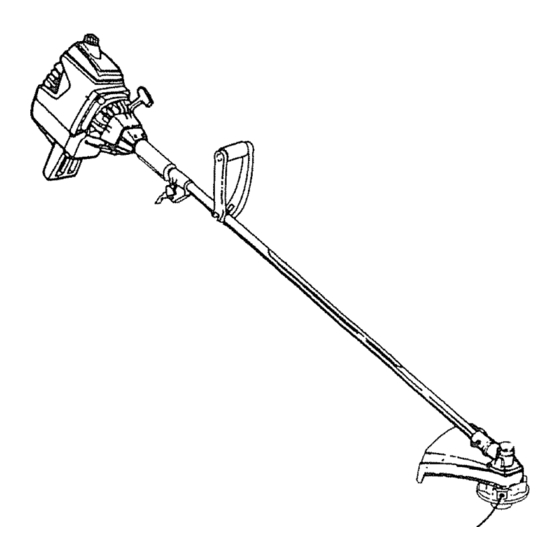
Page 8: Know Your Weedwacker
OPERATaON KNOW YOUR WEEDWACKER (Fig. 4) READ THIS OPERATOR'S MANUAL AND SAFETY RULES BEFORE OPERATING YOUR WEEDWACKERo Compare the illustrations with your unit to familiarize yourself with the location of the various controls and adjustments. Sav_ this manual for future reference. ON/OFF SWITCH HANDLE HANDLE... -
Page 9: Operation
OPERATION HOW TO USE YOUR WEEDWACKER STOPPING YOUR ENGINE ASSIST ° Move on/off switch to the "Off" position HANDLE o Uengine does not stop, move the choke lever clown (ful_ choke) CONTROLS (Fig. 5, 6 & 7) SAFETY LABEL THROTTLE TRIGGER TUBE o The throttle trigger a{lows for variable control of engine ASSIST HANDLE KNOB... - Page 10 OPERATnON BEFORE STARTING ENGINE: 40:1 2-CYCLE AIR-COOLED ENGINE OIL CRAFTSMAN 40:1 2-cycle engine oil (AtR-COOLED) is WARNING: strongly recommended This oil is specially blended with BE 'SURE TO READ THE FUEL SAFETY fuel stabilizers for increased fuel stability (extends fue! life...
- Page 11 OPERATION STOPPING YOUR ENGINE NOTE: If the engine has not started after 6 pulls (at half ,, ,Move the ON/OFF switch to the OFF position_ choke), check to make sure the ON/OFF switch and the o If engine does not stop, move the choke lever down choke lever are in lhe proper positions.
- Page 12 OPERATION SAFETY LINE TRIMMER SAFETY THROWN THE RAPIDLY MOVING LINE CAUSES OBJECTS TO BE WARNING: THROWN VIOLENTLY. THE DEBRIS SHIELD WILL NOT PROVIDE COMPLETE PROTECTIONTO THE OPERATOR FACE OR OTHERS. THE OPERATOR MUST WEAR A SAFETY SHIELD FACE SHIELD OR GOGGLES. ALWAYS WEAR HEAVY, LONG PANTS AND BOOTS.
- Page 13 OPERATION t=Lt, ..... LINE TRIMMER OPERATING TIPS (Fig. 10) TECHNIQUES (Fig. 11, 12, 13 & 14) • TRIMMING - Allow only the tip of the line to make con- USE MINIMUM SPEED AND DO NOT WARNING: tact.Do not force trimmerline intowork area. CROWD LINE WHEN...
-
Page 14: Air Filter
CUSTOMER RESPONSIBnLnTDES MAINTENANCE SCHEDULE Before Alter Every Every Yearly Service Dates Fill in dates as you complete regular service 5 Hrs. 25 Hrs. Check for damaged or worn parts 12 V2 Check for loose fasteners & parts ..Clean unit &labeis Clean air filter Clean/Inspect Spark...Arrestor Screen (if installed)and Muffler Drive Shaft Lubrication... -
Page 15: Customer Responsibilities
CUSTOMER RESPONSiBILiTIES .,,.i ....EVERY 5 HOURS DRIVE SHAFT LUBRICATION (Fig. 17) • Loosen the gear box clamp screw and the locating CLEAN FILTER (Fig. 15) screw from the gear box. A dirty air filter decreases the life and performance of the engine and increases fuel consumption and harmful : Remove the gear box from the tube, Remove the drive shaft from the tube.. -
Page 16: Fuel Filter
CUSTOMER RESPONSIBaLgT E$ REPLACE FUEL FILTER (Fig. 19 & 20) ,, Run fuel tank dry of fuel before proceeding with this step. o Remove fuel cap and allow it to hang to side of motor. retainer, holding it in tank opening and pull out i Using a small pair of needle nose pliers, grasp fuel cap •... -
Page 17: Service And Adjustments
SERVICE AND ADJUSTMENTS STARTER ROPE (Fig. 22, 23 & 24) DO NOT REMOVE THE RETAINING TAB DANGER: SCREW OR THE PULLEY. THE FRONT SPRING BENEATH PULLEY SHROUD UNDER TENSION AND CAN FLY OUT AND CAUSE SERIOUS INJURY. IF ANY NOSE CONE PART OF PULLEY HOUSING ASSEMBLY IS DAMAGED (OTHER THAN ROPE), DO NOT USE UNIT. -
Page 18: Line Replacement
SERVICE AND ADJUSTMENTS TRIMMER LiNE REPLACEMENT o Place the tap button over the spring and hub cylinder. o Align the slots in the tap button with the fins in the base WARNING: of the hub, Push parts together,. SEMI-AUTOMATIC HEAD PARTS THAT •... - Page 19 SERVICE AND ADJUSTMENTS COVER RNGER OVER NOTCH NOTCH LINE EXIT HOLE TAP BUTTON Figure 27 Figure 29 CATCH 1N" OF INNER LOCK TABS Figure 30 Figure 28 _19-...
-
Page 20: Carburetor Adjustments
SERVICE AND ADJUSTMENTS Carburetor adjustment is critical and tf done improp- ° Starl the engine and operate for three (3) minutes to erly can permanently damage the engine as well as warm up Go to "Adjusting Procedure". the carburetor, Please read all instructions and con. suit the Troubleshooting section of this manual... -
Page 21: Storage
° Open the semi-automatic head assembly and clean any dirt, grass or debris that has collected. CRAFTSMAN 40:1 2-cycle engine oil (AIR-COOLED) • Inspect the cutting line_Old cutting line may be chalky specially blended with fuel stabilizer. If you do not use or sticky to the touch. -
Page 22: Starting
TROUBLE SHOOTING POnNTS TROUBLE SHOOTING CHART SYMPTOM CAUSE CORRECTION I_ Fill tank with correct fuel mixture. 1 Fuel tank empty_ Engine will not start or 2 Engine flooded. 2. See "Starting Instructions", will run only for a 3_ Spark plug not tiring. 3,.