Table of Contents
Advertisement
Available languages
Available languages
Operator's
Manual
[RAFTSMAN°
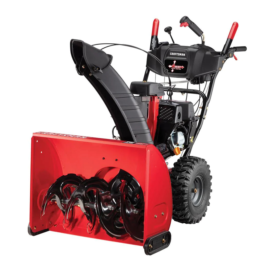
26" SNOW THROWER
Model No. 247.883700
CAUTION:
Before
using
this product,
read this
manual
and follow
all
safety
rules
and operating
instructions,
• SAFETY
ASSEMBLY
OPERATION
MAINTENANCE
PARTS LIST
ESPA_IOL
Sears, Roebuck
and Co., Hoffman
Estates,
IL 60179, U.S.A.
Visit our website:
www, craftsrnan.com
FORMNO.769-03346A
7/19/2007
Advertisement
Table of Contents

Related Manuals for Craftsman 247.883700


Summary of Contents for Craftsman 247.883700
- Page 1 Operator's Manual [RAFTSMAN° 26" SNOW THROWER Model No. 247.883700 • SAFETY ASSEMBLY OPERATION MAINTENANCE PARTS LIST CAUTION: Before using ESPA_IOL this product, read this manual and follow safety rules and operating instructions, Sears, Roebuck and Co., Hoffman Estates, IL 60179, U.S.A. Visit our website: www, craftsrnan.com FORMNO.769-03346A...
- Page 2 Assembly ..........Pages 8-11 Espa_ol ............. Page 40 Operation ..........Pages 12-15 ServiceNumbers ........BackCover Two -YearWarranty on Craftsman Snow Thrower This equipment iscovered by atwo-year warranty, provided that i tismaintained, lubricated, and tuned u paccording tothe instructions inthe operator's manual.
- Page 3 Congratulations on makinga smartpurchase.YournewCraftsman® Purchase a RepairProtectionAgreementnowand protectyourself productis designedand manufactured for yearsof dependableopera- from unexpectedhassleand expense. tion. But likeall products,it mayrequirerepairfrom time to time.That's Onceyou purchasethe Agreement,a simplephonecall is all that it whenhavinga RepairProtectionAgreementcansave you moneyand takesfor you toscheduleservice.Youcan call anytimeday or night, or aggravation.
- Page 4 This machine was built t obeoperated according totherules f or safe operation inthis manual. Aswith any type ofpower equipment, which, ifnot f ollowed, could e ndanger the personal This symbol points out i mportant safety i nstructions carelessness orerror onthe part o fthe operator can result inserious safety and/or property ofyourself and others.
-
Page 5: Operation
OPERATION MAINTENANCE & STORAGE Do not put hands or feet near rotatingparts, in the auger/impeller Nevertamperwith safetydevices.Checktheir properoperation housingor chuteassembly.Contactwiththe rotatingparts can amputate regularly.Referto the maintenanceandadjustmentsectionsof this handsand feet. manual. The auger/impellercontrol leveris a safetydevice.Neverbypassits Beforecleaning, repairing,or inspectingmachinedisengageall control operation.Doingso makesthe machineunsafeand maycause personal leversand stop the engine.Wait until the auger/impellercome to a injury. - Page 6 This page left intentionally blank.
- Page 7 1. KEEP AWAY FROMROTATING IMPELLER ANDAUGER. C ONTACT WITHIMPELLER OR AUGER CANAMPUTATE HANDS ANDFEET. 2. USECLEAN-OUT TOOL TOUNCLOG DISCHARGE C HUTE. 3. DISENGAGE CLUTCH L EVERS, STOP ENGINE, ANDREMAIN BEHIND HANDLES U NTIL ALL MOVING PARTS HAVE STOPPED BEFORE UNCLOGGING ORSERVICING MACHINE. 4.
-
Page 8: Removing From Carton
NOTE:References to rightor left sideof the snow throwerare determined from behindthe unit in the operatingposition(standing directlybehindthesnow thrower,facing the handlepanel). REMOVING FROM CARTON Cut the cornersof thecarton and lay the sidesflat on the ground. Removeand discardall packinginserts. Movethe snowthrowerout of thecarton. Makecertainthe carton hasbeen completelyemptiedbefore discardingit. - Page 9 Finishsecuringchute controlassemblyto chutesupport bracket with wing nutand hex screwremovedearlier.See Figure4. Checkthat all cables are properlyroutedthroughthe cableguide on top of the engine.See Figure5. The extensioncord is fastenedwith a cabletie to the rear of the auger housingforshippingpurposes.Cut the cabletie and removeit beforeoperatingthe unit. SET=UP Shear Pins...
- Page 10 Chute Clean=Out Tool A chute clean-out tool is fastenedto the topof theauger housing witha mountingclip. See Figure7.The tool is designedto cleara chuteassemblyof iceand snow.This item is fastenedwith a cable tie atthe factory.Cut thecable tie beforeoperatingthe snowthrower. Chute Clean-out Tool _leveruse yourhandsto cleara cloggedchute assembly.Shutoff _ngineand remainbehindhandlesuntilall movingparts havestoppedI _eforeusingthe clean-outtool to clearthe chuteassembly.
- Page 11 Auger Control .., ..Priorto operatingyoursnowthrower,carefullyread and followall instructionsbelow.Performall adjustmentstoverify yoursnow throweris operatingsafelyand properly. Checktheadjustmentof the augercontrol asfollows: Whenthe auger controlis releasedand in the disengaged"up" position,the cableshouldhavevery little slack. It shouldNOT be tight. In a well-ventilated area,start the snowthrowerengine.Refer to Startingthe Enginein the Operatlohn s ection.Makesurethe throttleis set in the FASTposition.
-
Page 12: Shift Lever
Shift Lever Four-Way ChuteControJ get Control EngineControJs Electric StarterOutlet RecoilStarh Handle Primer Control Figure10 Now that youhavesetupyoursnow thrower,it's importantto become NOTE:Do not turnthe ignitionkey in an attemptto startthe engine. acquainted with its controlsand features.Referto Figure10. Doingso maycauseit to break. CHOKE CONTROL SHIFT LEVER Theshift leveris locatedon the rightsideof the handle panel. - Page 13 THROTTLE CONTROL DRIVE CONTROL/AUGER CONTROL LOCK The throttlecontrolis locatedon the rear of theengine. DRIVE It regulatesthe speedof the engineand willshut off the enginewhenmovedintothe STOPposition. CONTROL SKID SHOES Positionthe skid shoes basedon surfaceconditions.Adjust upwardfor hard-packed snow.Adjustdownward when operatingon gravelor crushedrock surfaces. RECOIL STARTER HANDLE...
-
Page 14: Clean-Out Tool
CLEAN-OUT TOOL NOTE:A plasticdust cap maybe found insidethe fuel fill opening. Removeand discard,if present. Alwaysfill thefuel tank outdoorsand usea funnelor spout to fever useyour handsto clear a cloggedchute assembly.Shutoff preventspilling. gine and remainbehind handlesuntilall movingparts havestoppedI Fillfuel tank with clean,fresh,unleadedgasoline. fore usingthe clean-outtool toclear the chuteassembly, Neverfill thefuel tank completely.Fillthe tank to within 1/2"... -
Page 15: To Engage Augers
Oncethe engine starts,releasestarterbutton. NOTE: Whenselectinga Drive Speed,usethe slowerspeedsuntil you are comfortableand familiarwith theoperationof the snow As the enginewarms,slowlyrotatechokecontrolto theOFF thrower. position.If the enginefalters,quicklyrotatechoke controlback to FULL I,,_1 thenslowlyintothe OFF positionagain. Squeezethe drivecontrolagainstthe handleand the snow Whendisconnecting the extensioncord, alwaysunplugthe end throwerwill move.Releaseit and drive motionwillstop. -
Page 16: Engine Maintenance
ENGINE MAINTENANCE .--,, Beforelubricating, repairing,or inspecting, disengageall controls land stop engine.Wait untilall movingparts havecome toa complete [stop. FULL Maintain Oil Level Checking Engine Between FULL and ADD Be sureengine isuprightand level Unscrewoil fill capfrom oil fillertubeand wipedipstickclean. Screwoil fill capback into oil filler tube.Tightensecurely. Unscrewand removeoil fill cap from oil filler tube. - Page 17 Checking Spark Plug Checksparkplug yearlyor every 100operatinghours Cleanarea aroundspark plug. Remove and inspectspark plug. Replace spark plug if porcelainis crackedor if electrodesare pitted,burnedor fouledwith deposits Checkelectrodegap with a feelergaugeand set gap to .030 (0.76ram)if necessary.See Figure14. Reinstall spark plugand tightensecurely. NOTE:A resistorsparkplug must be usedfor replacement.
-
Page 18: Shave Plate And Skid Shoes
SHAVE PLATE AND SKID SHOES Theshaveplateand skid shoes on the bottomof the snowthrowerare subjectto wear.They shouldbe checkedperiodicallyand replaced whennecessary. Toremoveskid shoes: Remove the four carriagebolts and hexflangenuts whichsecure themto thesnow thrower. Reassemble n ewskid shoes with the fourcarriagebolts(two on eachside) and hexflangenuts.Referto Figure17. Toremoveshave plate: Remove the carriageboltsand hexnuts whichattach it to the snowthrowerhousing. -
Page 19: Belt Replacement
Chute Control Oncea seasonor every 25 hoursof operation,whicheveris earlier, checkwhetherthe four-waychutecontrol cables haveslackened.If the chutedoes notrotatefully,the chutecontrol cableswill haveto be adjusted.Referto Figure20. To adjustthese cables,proceedas follows: Usinga 1/2" wrench,loosenthe upper and lowerhexnuts foundon one cableadjuster. Graspthe metalcablehousingand gently pushupwardto take up slack (usuallyno morethan 1/4-inch)in the cablebefore retighteningbothhexnuts. - Page 20 Carefullypivot the snow throwerup and forwardso that it restson theauger housing. Removethe frame coverfrom the undersideof the snow thrower by removingfourself-tappingscrewswhich secureit. See Figure Removethe beltas follows.Referto Figure24. Loosenand removetheshoulderscrewwhich actsas a belt keeper. Unhookthesupport bracketspringfrom theframe. Removethe beltfrom aroundthe augerpulley,and slip the belt betweenthesupport bracketand the augerpulley.See Figure25.
-
Page 21: Friction Wheel Removal
Removethe beltas follows.Referto Figure26. Rollthe auger beltoff theengine pulley. Use a wrenchto pivotthe idler pulleytowardthe right. Lift the drive beltoff enginepulley. Carefullypivotthe snowthrowerup and forwardso that it restson the auger housing. Removethe framecoverfrom the undersideof thesnow thrower by removingfour self-tappingscrewswhich secureit. Referto Figure23. - Page 22 Carefullyremovethe hex nutand washerwhichsecuresthe hex shaftto the snowthrowerframeand lightlytap the shaft'send to dislodgethe ball bearingfrom the rightside of theframe.See Figure29. NOTE:Be carefulnot to damagethe threadson the shaft. Carefullypositionthe hexshaft downward and to the left before carefullyslidingthe frictionwheelassemblyoff the shaft. See Figure30.
-
Page 23: Maintenance
MAINTENANCE SCHEDULE Beforeperforming anytypeof maintenance/service, disengage all Followthe maintenance schedulegivenbelow•This chart describes controlsandstoptheengine. W aituntilall movingpartshavecometo serviceguidelinesonly•Usethe ServiceLog columnto keeptrackof a complete stop.Disconnect sparkplugwireandgroundit against t he completedmaintenance tasks•To locate the nearest Sears Service enginetoprevent u nintended starting. A lwayswearsafetyglassesduring Centeror to scheduleservice,simplycontactSears at 1-800-4-MY-HOME®. -
Page 24: Preparing Engine
If the snowthrowerwill notbe usedfor 30 days or longer,or if it is the end of the snowseasonwhenthe last possibilityof snow isgone,the equipmentneedsto be stored properly.Followstorageinstructionsbelowto ensuretop performancefromthe snow throwerfor many moreyears. PREPARING SNOW THROWER PREPARING ENGINE Whenstoringthe snowthrowerin an unventilatedor metalstor- Short=Term Storage age shed, careshouldbe taken to rustproofthe equipment.Using... - Page 25 Before performing anytypeof maintenance/service, disengage all controlsandstoptheengine. W aituntilall moving partshavecometo a complete stop.Disconnect sparkplugwireandgrounditagainstthe engineto prevent u nintended starting. A lwayswearsafetyglassesdurin( operation or whileperforming anyadjustments or repairs. Thissectionaddressesminor service issues,To locatethe nearestSears Service Center or to scheduleservice,simply contactSears at 1-800-4-MY-HOME®. Enginefails to start Chokecontrolnot in ONposition Movechoke controlto ON position.
- Page 26 Craftsman Snow Thrower IVlodel 247.883700...
- Page 27 Craftsman Snow Thrower Model 247.883700 731-2643 Clean-OutTool 718-04071 ThrustCollar 741-0663 i FlangeBearing 712-04065 FlangeLock Nut 710-0642 i Screw,1/4-20x 0.75 756-0981B Flat Idler Pulley 710-0347 Hex Bolt, 3/8-16x 1.75 790-00087A i BearingHousing 790-00080A Auger ldler Bracket 721-0325 i Plug 736-0174 WaveWasher...
- Page 28 Craftsman Snow Thrower Model 247.883700...
- Page 29 Craftsman Snow Thrower Model 247.883700 D" 684-04112B HandleEngagement A ssemblyRH 684-04162B Chute SupportBracket 738-04194 FlangeShoulderScrew 746-04396 SpeedSelectorCable 731-048940 LockPlate 736-0463 FlatWasher,.25 x .630x .0515 684-04250 Pivot Rod 710-0895 Hi-LoScrew,1/4-15x .75 735-0199A RubberBumper 710-0606 HexScrew,1/4-20x 1.50 710-04354 Screw,1/4-20x.375 731-04427A UpperChute 731-04896B ClutchLockCam...
- Page 30 Craftsman Snow Thrower IVlodel 247.883700...
- Page 31 Craftsman Snow Thrower Model 247.883700 656-04025A DiscAssembly,FrictionWheel 734-0255 ValveOnly 684-04153 731-04873 FrictionWheelAssembly,5.50D Spacer,1.25x .75x 3.0 684-04154 738-04168 SupportBracket,FrictionWheel Axle, .75x 22" 684-04156A ShiftAssembly,Rod 735-04099 Plug,3/8 ID 710-0627 Hex Screw,5/16-24,.750,Gr5 710-0809 Hex Screw,1/4-20,1.25,Gr5 710-0788 710-0191 Screw,1/4-20,1.000 Hex Screw,3/8-24, 1.25,Gr8 710-0896 Screw,1/4-14x .625 710-0672 Hex Screw,5/16-24,1.25,Gr5...
- Page 32 Craftsman Engine IVIodel OH195SA-72571 For Snow Thrower Model 247.883700 ! 73 310 -- 161B _--43 130A ",,. 186B 329A \"'2'_...
- Page 33 Craftsman Engine Model OH195SA=72571 For Snow Thrower Model 247.883700 ek.,.292 342B 110A ,_20 7ol 133_...
- Page 34 Craftsman Engine Model OH195SA=72571 For Snow Thrower Model 247.883700 |" 610961 FlywheelKey 37120B Cylinder(Incl.2, 20, 72) 26727 Dowel Pin i 611216 Flywheel(18Watt,W/Ring Gear) 650815 BellevilleWasher 31857 Oil DrainExtension(4-1/2")(1/4-18NPT) 650816 FlywheelNut 30969 ExtensionCap (1/4-18NPT) 651052 Washer 34443C SolidState Ignition 610118 SparkPlugCover 37108 GovernorRod(Incl.38)
- Page 35 Craftsman Engine Model OH195SA=72571 For Snow Thrower Model 247.883700 36824A ControlBracket(Incl. 206) 35062 IgnitionKey 610973 Terminal- ShortingOn-Off 329A 651060 Screw,8-32 X 23/64" 36632 ThrottleLink CarbCover 36873A 28942 Screw,10-32X 3/8" 650821 Screw,10-32X 1/2" 32410 SpeedControl Knob FuelTankBracket 36644A 36868 ChokeRod 342B...
- Page 36 Craftsman Engine IVlodel OH195SA=72571 For Snow Thrower IVlodel 247.883700 Th_s illustr3tion not d_ pic[ actual equipment is roe reference purposes only 590733 RewindStarter 590709 Pulley& RewindSpringAss'y. 590774 RepairKit 590574 StarterHandle 590535 98" StarterRope(cut to length) 590599A Spring Pin (Incl.4) Washer...
- Page 37 Craftsman Engine Model OH195SA=72571 For Snow Thrower Model 247.883700 ThrottleShaft & LeverAssembly 631767 ThrottleReturnSpring 631184 * Dust SealWasher 631183 * Dust Seal(Throttle) 631036 ThrottleShutter 650506 * ShutterScrew 632118 ChokeShaft & LeverAssembly 631890 ChokeShutter 630735 ChokePositioningSpring 632164 FuelFitting 651025 ThrottleCrackScrew/IdleSpeedScrew 630766 TensionSpring...
- Page 38 (This pageapplicablein the U.S.A.and Canadaonly.) Sears, Roebuck and Co., U.S.A. (Sears), the California Air Resources Board (CARB) and the United States Environmental Protection Agency (U.S. EPA) Emission ControJ System Warranty Statement (Owner's Defect Warranty Rights and ObJigations) EMISSIONCONTROL WARRANTYCOVERAGE ISAPPLICABLE TO CERTI- YEAR 1997AND LATERENGINES WHICHARE PURCHASED AND USED FlED ENGINESPURCHASEDIN CALIFORNIA IN 1995ANDTHEREAF- ELSEWHERE INTHE UNITEDSTATES (ANDAFTERJANUARY1,2001 IN...
- Page 39 Look For Relevant Emissions Durability Period and Air index information On Your Engine Emissions Label Engines that are certified to meet the California Air Resources Board (CARB) Tier 2 Emission Standards must display information regarding the Emissions Durability Period and the Air Index. Sears, Roebuck and Co., U.S.A. makes this information available to the consumer on our emission labels.
- Page 40 Craftsman Este equipoest,. cubiertopor una garanfiade dosahos, siempreque se mantenga,lubriquey ajustede acuerdocon las instrucciones del presentemanualdel operador.Duranteel aho de garanfia,si este equiposufrecualquierfalla producidapor defectosen materialeso manode obra,DEVUELVALO A SUCENTRODE PARTES& REPARACION SEARSM_,SCERCANO, y SearsIo reparar_t sin ningOn cargo.El serviciode garanfiaa domicilioester disponibleperose aplicar_t u n cargode traslado.
- Page 41 Felicitaciones por haberrealizadouna adquisici6ninteligente.El tecnicode Searspara los productosque requierenreparaci6n productoCraftsman@ que ha adquiridoest,. disehadoy fabricado a domicilio,adem_ts de una programaci6n convenientepara la parabrindar muchosahosde funcionamiento confiable.Perocomo reparaci6n todos losproductosa vecespuederequerirde reparaciones. E sen Unavez adquiridoel Acuerdo,puede programarel serviciocon ese momentocuandoel disponerde un Acuerdode protecci6npara tan s61orealizaruna Ilamadatelef6nica.Puede Ilamaren cualquier reparaciones le puedeahorrardineroy problemas.
- Page 42 Esta maquinafue construidapara ser operadade acuerdocon las reglas de seguridadcontenidasen este manual.AI igual quecon cualquiertipo instruccionesimportantesde seguridadquese deben de equipo motorizado,un descuidoo error por partedel operadorpuede respetarpara evitar poneren peligro su seguridad La presenciade este simbolo indicaque setrata de producirlesionesgraves.Estamaquinaes capazde amputarmanosy pies personaly/o materialy lade otraspersonas.
-
Page 43: Mantenimiento
OPERACION MANTENIMIENTO Y ALMACENAMIENTO • No pongalas maneso los piescerca de las piezas rotatorias,en la caja Nuncamanipulelosdispositivosde seguridadde manera imprudente. de labarrena/ motoro en el montajedel canal de descarga.El contacto Controleperi6dicamente que funcionende formaadecuada.Remftasea con las piezas rotatoriaspuedeproducirla amputacionde manosy pies. las seccionesde mantenimientoy ajustede este manual. -
Page 44: Montaje
NOTA:las referencias al ladoderechoo y ciertosde la m_tquina quitanievesedeterminandesdela parteposteriorde la unidaden posici6nde operaci6n(permaneciendo directamente detras de la m_tquina quitanieve,mirandohaciael panelde la manija). EXTRACCI6N DE LA UNIDAD DE LA CAJA Corte lasesquinasde la caja de cart6ny extiendalaen el piso Quitey descartetodos los insertosde empaque. Saquela maquinaquitanievede la caja. - Page 45 5. Termine deasegurar elmontaje decontrol del c anal alamensula desoporte del c anal conlatuerca demariposa yeltornillo hexagonal retirados anteriormente. Vea lafigura 4 . 6. Controle que todos l oscables est_n a decuadamente dirigidos a traves delagufa decables delaparte superior del m otor. Vea la figura 5 .
- Page 46 Herramienta de Limpieza del Canal Hay una herramienta de limpiezadel canal iajustadaa la parte superiorde la caja de la barrenacon un pasadorde ensamblado. Veala figura7. La herramienta est,, disehadapara limpiarel hielo y la nievedel montajede un canal.Este productose sujeta medianteuna uni6nde cableen la f_.brica.
- Page 47 Prueba de control de la barrena Antesde operarsu m_.quina quitanieve,lea atentamente y cumpla todas las instrucciones que aparecena continuaci6n. R ealice todos losajustesparaverificarque la m_tquina ester operandocon lsegur dad y correctamente. Compruebeel ajustedel controlde la barrenade la siguienteforma: Cuandose sueltael controlde la barrenay esteren posici6n desengranada arriba,el cable debetener muy pocojuego.NO debe estartenso.
-
Page 48: Llave De Encendido
AI activarel controlde obturaci6nse cierrala placa de obturaci6ndel carburadory se ayudaa encenderel motor. Cumple con los estfindares de seguridad de ANSI Lasmb.quinas quitanievede Craftsman cumplen conlosestandares de seguridad del instituto estadounidense d e est_mdares nacionales (ANSI). - Page 49 CONTROL DEL ESTRANGULADOR CONTROL DE LA BARRENA El control del estrangulador ester ubicadoen el motor. CONTROL Regulala velocidaddel motor,y Io apagacuandomuevael LA IBARRIENA controla la posici6nSTOR MANIJA DEL ARRANCADOR RETROCESO Esta manijase utiliza para arrancarel motormanualmente. BOTON BEL ARRANCABOR ELC:CTRICO Si oprimeel bot6ndel arrancadorelectricose engranael El controlde la barrenaestAubicadoen la manijaizquierda.Aprietela arrancadorelectricodel motorcuandose Ioenchufaa una...
- Page 50 CONTROL DEL CANAL DE Aceite 4 DIRECCIONES El motorse envi6con aceiteen el motor.Controleel nivelde aceite antes de cada operaci6npara asegurarsede que hayaaceite CHUTE DIRECTIONAL CONTROL suficienteen el motor.Paraobtenerm_tsinstrucciones, r emitasea los CHUTE TiLTUOWN pasosque aparecenen la p_tgina 52. Saquela varilladel nivelde aceitedel orificio de Ilenadode aceite.
- Page 51 NOTA:talvez sea necesarioun cebadoadicionalsi la temperaturaes inferiora 15° Fahrenheit. El arrancadorelectricoopcionalest,. equipadocon un cable de ali- mentaci6ny un enchufede tres terminalesconectadosa tierray ester Tome la manijadel arrancadorde retrocesoy tire de la cuerda disehadopara operarcon corrientedom_sticade 120voltios.Debe haciaafueralentamente. E n el momentoen el quese haga serutilizadocon un recept_.culo de tres terminalescorrectamente levementem_.sdificil tirarde la cuerda,permitaque la misma retrocedalentamente.
- Page 52 Antesde realizartareasde lubricaci6n,reparaci6no inspecci6n, desengranetodoslos controlesy detengael motor.Esperea que se _detengan todas as p ezas m6v es. Mantenga el nivel MANTENIMIENTO DE MOTOR FULL de aceite entre ControJ del aceite del motor AsegOrese de que el motorestAverticaly nivelado. (lleno) y ADD (agregue) Desenrosque el tap6nde Ilenadode aceitedel tubo de Ilenadode aceitey limpiela varillade nivelde aceite.
- Page 53 --,, Control de la bujia Controlelabujia anualmente o cada 100 horasde operaci6n. Limpie el _.reaalrededorde labujfa. Saquee inspeccionela bujia. Cambiela bujia si la porcelanaesta rotao si loselectrodosest_m: picados,quemadoso atoradoscon dep6sitos Controleel espaciodel electrodocon un calibradorde sepa- racionesy ajustedichoespacioa 0,030pulg (0,76mm) si es necesario.Vea la figura13.
- Page 54 --,, PLACA DE RASPADO Y ZAPATAS ANTIDESLIZANTES La placade raspadoy laszapatasantideslizantes ubicadasen la base de la m_.quina quitanieveest_tn sujetasa desgaste.Peri6dicamente deberiacontrolarlospernosy reemplazarlos cuandosea necesario. Para retirarlas zapatasantideslizantes: Quitelos cuatropernosdel carroy lastuercasde bridahexago- nalesque los asegurana la m_tquina quitanieve. Montelas nuevaszapatasantideslizantes concuatrospernos de carro (dosen cada lado)y las tuercasde brida hexagonales.
-
Page 55: Reemplazo De La Correa
Ubiquela m_nsulahaciaarribapara brindarm_ts juego (o hacia abajopara aumentarla tensi6ndel cable). Vuelvaa apretarla tuercahexagonal s uperior. Control del canal Unavez por temporadao cada25 horasde operaci6n,Io que suceda antes,revisesi los cablesdel control del canalde cuatrodirecciones se han aflojado.Si el canalno gira completamente, e s necesario ajustarlos cablesde control del canal.Vea la figura19. - Page 56 Saquela cubierta del marcodesdedebajode la mgtquina quitanieveretirandoloscuatro tornillosautorroscantes que la aseguran.Vea la figura22. Aflojey retireel tornilloconrebordeque actOacomoguarda de la correa.Vea la figura23. Desenganche el resortede la m6nsulade soportedel marco. Retire la correade alrededorde la poleade la barrenay deslice la mismaentre la m6nsulade soportey la polea de la barrena. Vea la figura24.
- Page 57 Saquela correade la barrenade la poleadel motor. Tome la polea Iocay girela haciala derecha.Vea la figura Levantela correade la barrenapara sacarlade la polea del motor. 4. Girecon cuidadola m_tquina quitanievehaciaarriba y hacia delantede maneraque quedeapoyadasobrela cajade la barrena. 5. Saquela cubiertadel marcodesdedebajode la m_tquina quita nieveretirandoloscuatro tornillosautorroscantes que la aseguran.Veala figura22.
- Page 58 Retirecon cuidadola tuercahexagonal y la arandelaque sujetan el eje hexagonal a l marcode la maquinaquitanieve,y golpee suavemente el extremodel eje paradesplazarel cojinetede bolasdel ladoderechodel marco.Vea la figura28. NOTA:Tengacuidadode no dahar lasroscasdel eje. Con cuidado,ubiqueel eje hexagonal h aciaabajo y haciala izquierdaantesde deslizarcon precauci6nel montajede la rueda de fricci6nfueradel eje.Vea la figura29.
- Page 59 EtARRENAS Las barrenasest_majustadasal eje espiralcon dospasadoresde cuchillay pasadores de chaveta.Si la barrenagolpeaun objeto extrahoo una barrade hielo,la m_.quina quitanieveester disehadade maneraque los pasadoresse puedencortar.Si las barrenasno giran, verifiquesi los pasadores se cortaron.Vea la figura 31. NUNCAcambie lospasadoresde cuchillade las barrenaspor otra cosa que los pasadoresde cuchillade repuestodel fabricantedel equipooriginal,NO de pieza738-04124A.
- Page 60 Si no sevaa utilizael equipodurante 30 diaso mAs,o si esel finalde la temporada de nieveyya no existeposibilidad de quenieve,esnecesario almacenar e l equipode manera adecuada. S igalas instrucciones de almacenamiento quese indicana continuaci6n paragarantizar e l rendimiento mAximo de la mAquina quitanieve durantemuchos ahos. PREPARACION DE LA MAQUINA QUITANIEVE PREPARACION DEL MOTOR...
- Page 61 luier tipodel mantenimiento/servicio, sueltetodos los mandosy pare el motor.Esperehastaque todas las partesde Ilevepuestoscristalesinastillablesdurantela operaci6no realizandocualquierajuste o reparaciones. Esta secci6nse dirigea cuestione$de serviciomenores, Localizarel mac cereanoChamuscael Centrode Servicio o programarel servicio,simplemente ponerseen contactoChamusca en 1-800-4-MY-HOME®. = II • El motor no arranca /a palanea de obturacidn no estfi en la Pongael interruptor en la posici6nCHOKE(obtura- posici6nON (encendido)
- Page 62 (Esta p_tginase aplica s61oen EE.UU. y CanadA). Sears, Roebuck and Co., LI.S.Ao (Sears), el Coneejo de Recureoe Ambientalee de California (CARB) y la Agencia de Protecci6n Ambiental de los Eetados Unidoe (EPA) Declaracion de garant[a del sieterna de control de emisionee (derechoe y obmigacionee de la garant[a de defectoe del propi-...
- Page 63 Busque el periodo de duracion de emisiones importantes yla informaci6n de clasificacion de aire en la etiqueta de emisiones de su motor Los motores cuyo cumplimiento con los est&ndares de emisi6n Tier 2 de la Comisi6n de Recursos Ambientales de California (CARB) est6 certificado deben exhibir la informaci6n relacionada con el periodo de duraci6n de las emisiones y la clasificaci6n de aire.
- Page 64 Your Home For repair - in your home - of all major brand appliances, lawn and garden equipment, or heating and cooling systems, no matter who made it, no matter who sold it! For the replacement parts, accessories owner's manuals that you need to do-it-yourself. For Sears professional installation of home appliances and items like garage door openers and water heaters.