Table of Contents
Advertisement
Advertisement
Table of Contents

Related Manuals for Husqvarna 8527STE


Summary of Contents for Husqvarna 8527STE
- Page 1 Husqvarna 8527STE Owner's Manual...
- Page 2 SAFETY RULES Safe Operation Practices for Snow Throwers IMPORTANT: This machine is capable of amputating hands and feet and throwing objects. Failure to observe the following safety instructions could result in serious injury or death. Do not operate the equipment without wearing ade- quate winter outer garments.
-
Page 3: Maintenance And Storage
• Donotputhands orfeetnearor under rotating parts. • Do not overload the machine capacity by attempting Keepclearofthe discharge o pening andfrontauger to clear snow at too fast a rate. areaat alltimes. • Never operate the machine at high transport speeds • Exercise e xtreme caution when operating o nor cross- on slippery surfaces. - Page 4 SAFETY RULES ............MAINTENANCE ............. 14-15 PRODUCT SPECIFICATIONS ........MAINTENANCE SCHEDULE ........CUSTOMER RESPONSIBILITIES ........ SERVICE AND ADJUSTMENTS ......16-18 WARRANTY ..............STORAGE ..............ASSEMBLY / PRE-OPERATION ....... TROUBLESHOOTING ..........OPERATION ............8-13 REPAIR PART_ ............20-31 PARTS PACKED SEPARATELY IN CARTON (1) AUGER CONTROL ROD (1) TRACTION DRIVE CONTROL ROD (1) DISCHARGE...
-
Page 5: Assembly / Pre-Operation
ASSEMBLY / PRE-OPERATION Read these instructions and this manual in its entirety before you attempt to assemble or operate your new snow thrower. Your new snow thrower has been assembled at the factory with the exception of those parts left unassembled for shipping purposes. - Page 6 ASSEMBLY / PRE-OPERATION INSTALL TRACTION DRIVE CONTROL ROD INSTALL AUGER CONTROL ROD (See Figs. 5 and 6) (See Figs. 3 and 4) The auger control rod has the short loop on the end of the spring as shown. The traction drive control rod has the long loop on the end of the spring as shown.
- Page 7 ASSEMBLY / PRE-OPERATION INSTALL DISCHARGE CHUTE/CHUTE ROTATER HEAD CHECKTIRE PRESSURE (See Fig. 7) The tires on your snow thrower were overinflated at the fac- tory for shipping purposes. Correct and equal tire pressure NOTE: The multi-wrench provided in your parts bag may be used to install the chute rotater head.
-
Page 8: Operation
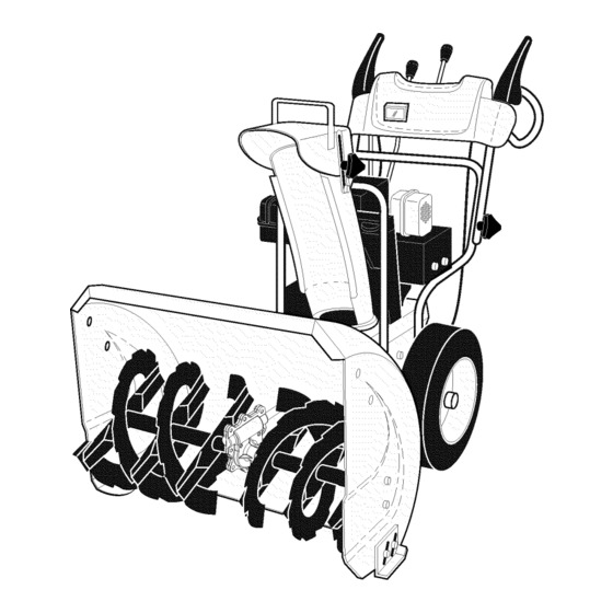
OPERATION KNOW YOUR SNOW THROWER READ THIS OWNER'S MANUAL AND ALL SAFETY RULES BEFORE OPERATING YOUR SNOW THROWER. Compare the illustrations with your snow thrower to familiarize yourself with the location of various controls and adjustments. Save this manual for future reference. These symbols may appear on your snow thrower or in literature supplied with the product. - Page 9 OPERATION SPARK ENGINE OIL CAP AUGER DISCHARGE CHUTECONTROLLEVER PLUG ~ .WITH DIPSTICK CONTROL SAFETY LEVER DRIVE SPEED IGNITION CONTROL LEVER GASOLINE FILLER 'TRACTION CHUTE CHOKE DRIVE DEFLECTOR CON- CONTROL LEVER THROTTLE / ENGINE CONTROL OIL DRAIN PLUG RECOIL POWER (AUXILIARY) CORD STARTER PLUG...
-
Page 10: How To Use Your Snow Thrower
OPERATION The operation of any snow thrower can result TO USE CHOKE CONTROL (See Fig. 11) in foreign objects thrown into the eyes, which The choke control is located on the engine. Use the choke can result in severe eye damage. Always wear control whenever you are starting a cold engine. - Page 11 OPERATION TO MOVE FORWARD AND BACKWARD (See Fig. 15) HIGH POSITION SELF-PROPELLING, forward and reverse movement of the snow thrower, is controlled by the traction drive control lever located on the left side handle. • Squeeze traction drive control lever to handle to engage xz/'/]/ the drive system.
-
Page 12: Before Starting The Engine
OPERATION TO ADJUST SKID PLATES (See Fig. 16) [& WARNING: Wipe off any spilled oil or NOTE: The wrench provided in your parts bag may be used fuel. Do not store, spill or use gasoline to adjust the skid plates. near an open flame. -
Page 13: Snow Throwing Tips
OPERATION COLD START- ELECTRIC STARTER ELECTRIC STARTER Insert safety ignition key into the ignition slot until it Connect the power cord to the engine. clicks. DO NOT turn the key. Keep the extra safety Plug the other end of the power cord into a three-hole ignition key in a safe place. -
Page 14: Maintenance
MAINTENANCE MAINTENANCE FILL IN DATES AS YOU COMPLETE REGULAR SERVICE Check for Loose Fasteners Clean / Inspect Snow Thrower Check/Replace V-Belts Lubrication Chart Check Engine Oil Level Change Engine Oil Inspect Muffler Check/Replace Spark Plug Empty Fuel Tank GENERAL RECOMMENDATIONS LUBRICATION CHART The warranty on this snow thrower does not cover items that... - Page 15 MAINTENANCE V-BELTS TO CHANGE ENGINE OIL Check V-belts for deterioration and wear after every 50 Determine temperature range anticipated before next oil hours of operation and replace if necessary. The belts change. All oil must meet API service classification SF-SJ. are not adjustable.
-
Page 16: Service And Adjustments
SERVICE AND ADJUSTMENTS Disengage all controls and move throttle control to WARNING: To avoid serious injury, STOP position. Wait for all moving parts to stop. before performing any service or ad- Disconnect spark plug wire from spark plug and place justments: it wear it cannot come in contact with spark plug. - Page 17 SERVICE AND ADJUSTMENTS TO REPLACE BELTS (See Fig. 20) The auger and traction drive belts are not adjustable. If the HINT: Insert a 3/8" drive ratchet (in the "ON" position) into belts are damaged or begin to slip from wear, they should the square hole in idler arm and rotate ratchet clockwise be replaced.
- Page 18 TO REMOVE WHEELS (See Fig. 21) NOTE: To seal punctures or prevent flat tires due to slow leaks, tire sealant may be purchased from your local parts • Remove the klik pin and remove wheel from axle. dealer.Tire sealant also prevents tire dry rot and corrosion. IMPORTANT: When installing wheel, be sure to use the in- nermost hole in axle and the wheel hub hole.
-
Page 19: Troubleshooting
TROUBLESHOOTING See appropriate section in manual unless directed to a qualified service center. PROBLEM CAUSE CORRECTION Does not start Fuel shut-off valve (if so Turn fuel shut-off valve to OPEN position. equipped) in OFF position. Safety ignition key Insert safety ignition key. is not inserted. - Page 20 REPAIR PARTS AUGER HOUSING / IMPELLER ASSEMBLY SNOWTHROWER - - MODEL NO. 8527STE (HL8527STEA), PRODUCT NO. 954 22 36-54 4 9"_'-'T' "_2; _ Q,_iTt/_g_._ 3234__37 44 27 432i -20 23 24...
- Page 21 REPAIR PARTS AUGER HOUSING / IMPELLER ASSEMBLY SNOW THROWER - - MODEL NO. 8527STE (HL8527STEA), PRODUCT NO. 954 22 36-54 PART DESCRIPTION 532 05 38-47 Washer, Flat 532 18 10-83 Pulley, Impeller 532 17 53-23 Bearing Assembly, Flange 532 15 53-77 Nut, Hex Flange 5/16-18 532 18 03-55 Bolt, Flat Head, Carriage...
- Page 22 REPAIR PARTS CONTROL PANEL / DISCHARGE CHUTE SNOWTHROWER - - MODEL NO. 8527STE (HL8527STEA), PRODUCT NO. 954 22 36-54...
- Page 23 REPAIR PARTS CONTROL PANEL/DISCHARGE CHUTE SNOW THROWER - - MODEL NO. 8527STE (HL8527STEA), PRODUCT NO. 954 22 36-54 PART DESCRIPTION 532 18 33-34 Knob, Lever 8175010-10 Screw #10-24x5/8 532 18 41-14 Strap, Slotted 873 80 06-00 Nut, Lock 3/8-16 819 13 13-16 Washer, Flat 3/8 532 17 86-59 Control Assembly, Chute Rotater...
- Page 24 REPAIR PARTS HANDLES SNOWTHROWER - - MODEL NO. 8527STE (HL8527STEA), PRODUCT NO. 954 22 36-54...
- Page 25 REPAIR PARTS HANDLES SNOW THROWER - - MODEL NO. 8527STE (HL8527STEA), PRODUCT NO. 954 22 36-54 PART DESCRIPTION 5321841-10 Lever, Auger Control, RH 5321841-09 Lever, Traction Drive Control, LH 532 1794-39 Nut, Cage 1/4-20 532 1788-88 Bushing, Flange 532 1696-75 Retainer, Hairpin 532 1804-02 Screw, Hex Head 1/4-20 x 3/4...
- Page 26 REPAIR PARTS DRIVE SNOWTHROWER - - MODEL NO. 8527STE (HL8527STEA), PRODUCT NO. 954 22 36-54 °*..o...
- Page 27 REPAIR PARTS DRIVE SNOW THROWER - - MODEL NO. 8527STE (HL8527STEA), PRODUCT NO. 954 22 36-54 PART DESCRIPTION 5321463-15 Screw, HexHead 5/16-18x3/4 873 80 05-00 Nut, Lock 5/16-18 532 15 5415 Washer, Flat 8174905-08 Screw, HexHead 5/16-18xl/2 532 18 00-17 Bearing, Flange 532 18 01-34 Shaft, Auxiliary...
-
Page 28: Chassis / Engine / Pulleys
REPAIR PARTS CHASSIS / ENGINE / PULLEYS SNOWTHROWER - - MODEL NO. 8527STE (HL8527STEA), PRODUCT NO. 954 22 36-54... - Page 29 REPAIR PARTS CHASSIS / ENGINE / PULLEYS SNOW THROWER - - MODEL NO. 8527STE (HL8527STEA), PRODUCT NO. 954 22 36-54 PART DESCRIPTION 532 18 10-44 Spring, Traction Idler 532 18 05-22 Pulley, Idler (2-1/4) Engine, Tecumseh, Model Number HMSK85 (Order parts from Engine manufacturer) 874 78 05-20 Screw, Hex Head 5/16-18 x 1-1/4 532 05 92-89...
- Page 30 REPAIR PARTS WHEELS / DECALS SNOWTHROWER - - MODEL NO. 8527STE (HL8527STEA), PRODUCT NO. 954 22 36-54 .°.,'" ...- .._ ..
- Page 31 DESCRIPTION 5321810-38 Decal, Danger 5321879-11 Decal Husqvarna 5321810-34 Decal Danger, Deflector 5321810-41 Decal Danger 532 1875-84 Decal Husqvarna, 8527STE 5321810-32 Decal Instruction 532 1557-98 Decal Traction Lever 532 1558-00 Decal Auger Lever 5321810-36 Decal Speed Control 532 15 57-94 Decal Husqvarna, Crown...
-
Page 32: Warranty Statement
Husqvarna will repair or replace defective components without charge for parts or labor if a component fails because of a defect in material or workmanship during the warranty period.