Panasonic WJ-NV200K Installation Manual
Network disk recorder
Hide thumbs
Also See for WJ-NV200K:
- Operating instructions manual (97 pages) ,
- Installation manual (94 pages) ,
- Quick reference manual (4 pages)
Table of Contents
Advertisement
Quick Links
Download this manual
See also:
Quick Reference Manual
Advertisement
Table of Contents

Related Manuals for Panasonic WJ-NV200K


Summary of Contents for Panasonic WJ-NV200K
-
Page 1: Installation Guide
Installation Guide Network Disk Recorder WJ-NV200K Model No. WJ-NV200K/G Before attempting to connect or operate this product, please read these instructions carefully and save this manual for future use. The model number is abbreviated in some descriptions in this manual. - Page 2 • The connections should comply with local electrical code. CAUTION: UL listed model No.: Before attempting to connect or operate this product, please WJ-NV200K read the label on the bottom. For Canada This Class A digital apparatus complies with Canadian ICES-003.
- Page 3 If you lose the fuse cover the plug must not be used until a replacement 2004/108/EC. cover is obtained. A replacement fuse cover can be purchased from your local Panasonic Wir erklären in alleiniger Verantwortung, daß das Produkt, auf das sich Dealer.
-
Page 4: Limitation Of Liability
OF THE PRODUCT; (5) ANY PROBLEM, CONSEQUENTIAL INCONVENIENCE, OR LOSS OR DAMAGE, ARISING OUT OF THE SYSTEM COMBINED BY THE DEVICES OF THIRD PARTY; Warranty for U.S. WJ-NV200K is warranted for three years. Refer to the provided warranty about further information. -
Page 5: Important Safety Instructions
Important safety instructions 1) Read these instructions. 2) Keep these instructions. 3) Heed all warnings. 4) Follow all instructions. 5) Do not use this apparatus near water. 6) Clean only with dry cloth. 7) Do not block any ventilation openings. Install in accordance with the manufacturer's instructions. 8) Do not install near any heat sources such as radiators, heat registers, stoves, or other apparatus (including amplifiers) that produce heat. -
Page 6: Table Of Contents
Important safety instructions .........5 Configure the settings relating to the mail Preface ................7 notification [e-Mail] ............63 Features .................7 Configure the Panasonic alarm protocol settings System configuration ..........8 [Panasonic alarm protocol] ........64 About the user manuals ..........9 Configure the settings relating to NTP/SNMP System requirements for a PC ........9... -
Page 7: Preface
Preface The network disk recorders WJ-NV200K and WJ-NV200K/G (hereinafter, recorders) are designed for use within a surveillance system, and record images/audio from up to 16 network cameras (hereinafter, cameras) on the hard disk drives. Up to 16 camer- as can be registered. -
Page 8: System Configuration
System configuration Main monitor Live monitor Powered speaker Network camera (x 16 max.) Network... -
Page 9: About The User Manuals
Depending on descriptions, the model name of this recorder may be omitted as "NV200" in the manuals and on the setup. The screens used in these operating instructions show the case in which WJ-NV200K is used and 16 cameras are connected. -
Page 10: Trademarks And Registered Trademarks
• Customers can duplicate, distribute and modify the source code of the software under license of GPL and/or LGPL. • Refer to the "readme.txt" file on the provided CD-ROM for further information about the source code of the software con- tained in this product and copyright notice comprised in the GPL/LGPL software. • Please note that Panasonic shall not respond to any inquiries regarding the source code. Copyright Except for open source software licensed base on GPL/LGPL and so on, distributing, copying, disassembling, reverse compiling, reverse engineering, and also exporting in violation of export laws of the software provided with this product are all expressly pro- hibited. -
Page 11: Network Security
Network security As you will use this product connected to a network, your attention is called to the following security risks. q Leakage or theft of information through this product w Use of this product for illegal operations by persons with malicious intent e Interference with or stoppage of this product by persons with malicious intent It is your responsibility to take precautions such as those described below to protect yourself against the above network security risks. -
Page 12: About The Face Matching Function
About the face matching function This recorder (WJ-NV200K or WJ-NV200K/G) has the face matching function that compares the registered face images with a face displayed on live images to detect a person with a closer match. When the person is detected, it is possible to activate an alarm notification. - Page 13 • Adjust the height, angle of depression and vertical angular field of view of the camera so that the angle between the camera and face ("θ" in the illustration) becomes 15° or less. Angle of depression Camera Vertical angular field of view Person θ (Angle between the camera and face) Example of camera adjustment (When shooting a person whose height is 170 cm {5.58'}) Vertical angular field of view...
- Page 14 Cases not suited for face matching The performance of the face matching function varies depending on such conditions as the camera installation, camera settings, camera adjustment, surroundings and photographic subjects. Therefore, face matching may not be performed in the following cases.
-
Page 15: Precautions
+25 °C {77 °F} and to replace them after around 18 000 (WJ-NV200K), 220 V – 240 V AC 50 Hz/60 Hz (WJ-NV200K/G). Do not connect to the outlet that provides hours of operation. - Page 16 MPEG-4 Visual Patent Portfolio License This product is licensed under the MPEG-4 Visual Patent Portfolio License for the personal and non-commercial use of a consumer for (i) encoding video in compliance with the MPEG-4 Visual Standard ("MPEG-4 Video") and/or (ii) decoding MPEG-4 Video that was encoded by a consumer engaged in a personal and non-commercial activity and/or was obtained from a video provider licensed by MPEG LA to...
-
Page 17: Precautions For Installation
Precautions for installation This product is designed to be used indoors. Avoid placing this product near noise sources If the cables are placed near noise sources such as fluores- Do not place this product in the following places: cent lamps, noises may be produced. In this case, rewire • Locations exposed to direct sunlight avoiding the noise sources, or move the product to a place • Locations subject to having strong vibration or impact... -
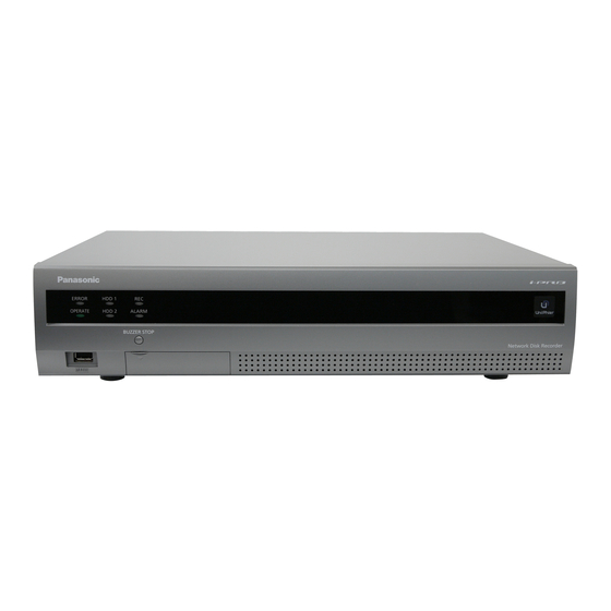
Page 18: Major Operating Controls And Their Functions
Major operating controls and their functions Front view q Status indicators w Buzzer stop button t SDHC/SD memory card slot r Restart button e Mouse connection port * It is impossible to connect a mouse to the mouse connection port if the connector from the mouse is upside down. - Page 19 Insert an SD memory card (option) Step 1 Open the SDHC/SD memory card slot cover. Pull the tab down. SDHC/SD memory card slot cover Step 2 Insert a SD memory card all the way into the slot until it clicks. When inserting an SD memory card, confirm that the label on the SD memory card is upside and only the...
-
Page 20: Rear View
Rear view !2 HDD slots !3 SIGNAL GND terminal !1 Monitor output connector (HDMI) Link indicator Access indicator !0 Audio output connector (RCA pin jack) y Power cord inlet u Alarm/control connector o Spot output connector (BNC) (D-sub 25-pin) i Network port y Power cord inlet [AC IN] !0 Audio output connector (RCA pin jack) [AUDIO Connect the provided power cord to this inlet. -
Page 21: User/Host Management
User/Host management It is necessary to register users who operate the recorder and hosts (PC) that accesses the recorder via a network such as a LAN. Up to 16 users can be registered. It is possible to register the following for the user information. Item Description User name... -
Page 22: Operations Flow
Operations flow z Connect the recorder to each device. Connection ☞ Page 23 x Turn on the power of the recorder. Turn on the recorder ☞ Page 31 c Enter the "Registration Key" of the recorder by following Obtain the license (Registration Key) the instructions on the provided Activation Key Card. -
Page 23: Connection
Up to 16 cameras can be connected to the recorder via a switching hub. Use a LAN cable (straight) to connect the recorder and the switching hub. Recorder LAN cable (commercially available) 10BASE-T/100BASE-X/1000BASE-T: category 5e or better (straight) for WJ-NV200K category 7 (straight) for WJ-NV200K/G Switching hub Network camera (x 16 max.) -
Page 24: Connection Of Monitors
Connection of monitors Connect the main monitor that displays recorded images or the setup menu to the monitor output connector (HDMI) using an HDMI cable (option). Connect the live monitor to the spot output connector (BNC) using a BNC cable (locally procured). Main monitor * When outputting audio Connect a powered speaker. -
Page 25: Connection Of A Pc
Default gateway: 192.168.0.1 (except 0, 1, 250 and 255) LAN cable (commercially available) Subnet mask: 255.255.255.0 10BASE-T/ 100BASE-TX/1000BASE-T: Default gateway: 192.168.0.1 category 5e or better (straight) for WJ-NV200K category 7 (straight) for WJ-NV200K/G Network Switching hub IP address: 192.168.0.1 Subnet mask: 255.255.255.0... -
Page 26: About The Connector
The connector to be used should be compatible with the pin array. Pin array The pin array is different from other Panasonic recorders. Make sure that the connection is correct referring to the following. - Page 27 Connection for the auto time adjustment function When a signal output from the other device is supplied to the time adjustment signal input (pin no. 20) and the time difference between the recorder and the other device is 29 minutes or less, the clock of the recorder will be set to the time set for the other device.
-
Page 28: Time And Polarities Of The Alarm/Control Connector
Alarm connection When a signal output from the other device is supplied to the Alarm input 1 to 9 terminals (pin nos. 1 - 9), recording or an alarm action will be performed in accordance with the settings. When an alarm device such as a buzzer, a lamp, etc., is installed outside, connect them to the Alarm output terminal (pin no. 21). Sensor Door security switch... -
Page 29: Installation Or Replacement Of The Hard Disk Drives
Installation or replacement of the hard disk drives Before installing the hard disk drives, turn off the power of this recorder first. When replacing the hard disk drives, the procedures will be same as those of installation. When installing or replacing the hard disk drives for playback use only, perform the link pro- cess. -
Page 30: Replace The Hard Disk Drives
Note: Important: • Hard disk drives are locally procured. Contact your deal- • Hard disk drives are precise devices. Handle with care er for purchasing, installing, and replacing the hard disk while keeping the following in mind. drives. • Do not subject the hard disk drive to any vibration or impact. • Before touching the hard disk drive, eliminate static elec- tricity by touching a steel locker, etc. When holding the hard disk drive, hold the both sides of the hard disk drive. -
Page 31: Turn On The Recorder
"Registration Key" by following the WJ-NV200K: 120 V AC, 60 Hz procedures on page 33. WJ-NV200K/G: 220 V - 240 V AC, 50 Hz/60 Hz → The [OPERATE] indicator will light, the system check of Note: the recorder and the hard disk drives will start, and the • When the "Login" window is displayed during operation... -
Page 32: Turn Off The Power Of The Recorder
Turn off the power of the recorder Turn off the power of the recorder. When turning off the power, follow the procedure "During recording" or the procedure "During playback" depending on the current operation status. During recording Step 1 Step 2 Select "Off"... -
Page 33: Register The License
Register the license When using this recorder for the first time, it is necessary to register the license for the recorder. Important: • After registering the "Registration Key" for the recorder (when using the recorder for the first time), be sure to click the [Restart] button to restart the recorder. - Page 34 Step 5 Click the [Setup >] button of [Registration of license]. → The registration window will be displayed. Step 6 Click the [Registration >] button of "Product" - "Registration Key". → The "Registration key input" window to register the license will be displayed. Step 7 Enter the "Registration key"...
-
Page 35: Basic Operations
Basic operations The recorder can be operated using the provided mouse connected to the mouse connection port on the front side of the recorder. It is also possible to perform operations (except for the settings) of the recorder from the web browser. Refer to the Operating Instructions (PDF) for further information about the operations from the web browser. - Page 36 About the operation of on-screen keyboard Setting items can be entered using the on-screen keyboard. When clicking the [ ] icon beside the entry field, the on-screen keyboard will be displayed, and it will become possible to enter characters by clicking the character keys on the keyboard. Entry field Language selection pull-down menu Click the [...
-
Page 37: Setup Menu
Setup menu Configuration of each setting item in the setup menu should be completed in advance to use this recorder. The setup menu has the following levels for the setting items. On "Easy Start", the minimum settings required to operate the recorder will be performed, but other settings will remain default. -
Page 38: Configure The Minimum Settings [Easy Start]
Configure the minimum settings [Easy Start] The minimum settings required to operate the recorder, such as the date & time, camera registration, recording, can be config- ured on the setup menu - the "Quick setup" menu - "Easy Start". First, configure the minimum settings on "Easy Start", and to configure more advanced settings, go to each setup page. Available settings on "Easy Start"... - Page 39 (4 multi-screen segments when 4 [Model] cameras are connected in the system, 9 multi-screen seg- When Panasonic network cameras are used, the model ments when 9 cameras are connected, 16 multi-screen seg- numbers will be displayed.
- Page 40 • When the HDD saving mode is set, the actual recording days are longer than the referenced recording days. (☞ Page 50) • The HDD consumption for the event recording will be excluded. • If a camera manufactured by other than Panasonic is used, the value of "Referenced recording days" will not be displayed. Step 9 Click the [Exit] button. → Saves the settings and returns to the top screen of the...
-
Page 41: Configure The Basic Settings [Basic Setup]
Configure the basic settings [Basic setup] The basic settings of the recorder such as date & time and recording mode, etc. can be configured on the "Basic setup" page. The "Basic setup" page provides access to the [Date/Language], [Camera] and [REC & event] pages. Display the basic setup pages Click the desired button on the setup menu. -
Page 42: Display Format
To return to the previous page, click the [Back] button. 24 h: 15:00:00 12 h: 03:00:00 PM Important: Default: 12 h (WJ-NV200K) • Setting is impossible when the interval between start (In)/ 24 h (WJ-NV200K/G) end (Out) is less than an hour. ■ Time zone [Auto time adjustment] Select the time zone and shift to/from daylight saving time. - Page 43 [Language] tab Select the display language for the main monitor and for the web browser on the PC. [Language] 日本語/ English/ Français/ Español/ Deutsch/ Italiano/ Русский/ Default: English...
-
Page 44: Camera Setup [Camera]
Camera setup [Camera] The "Camera" page has 2 tabs; the [Camera registration] tab and the [Camera setup] tab. [Camera registration] tab Perform settings such as the network settings of the camera (IP address and port number), and the display position on the main monitor. - Page 45 Change the registered information [Registered information] Click the [Setup >] button for "Change the registered information" on the [Camera registration] tab to display the following items. After editing the settings, click the [OK] button to save the settings and return to the [Camera registration] tab. Set a port number from 1 - 65535 for use by the camera.
- Page 46 Interchange camera numbers [Change the display position of camera] Click the [Setup >] button for "Change the display position of camera" on the [Camera registration] tab to display the following items. The registered cameras will be displayed on the screen in the order of 1, 2 ...16 from top left to right. (4 multi-screen segments when 4 cameras are connected in the system, 16 multi-screen segments when 12 cameras are connected) To interchange camera numbers, drag the camera image to be moved with the mouse and drop on the desired position.
-
Page 47: Camera Selection
Set up date & time display [Date & time display] Select the date & time display position for each camera and transmit it to the cameras to change the camera settings. Clicking the [Setup >] button for "Date & time display" on the [Camera setup] tab will display the following items. Note: • The position to display the title edited on "Display title"... - Page 48 [Display Title] The camera title registered on the [Main monitor] tab of To transmit the settings to the camera, mark this item, and the monitor page can be used as display title. Clicking edit the title displayed on the image. Clicking the [Edit >] but- this button will copy the camera title to the "Display Title"...
- Page 49 Set up VMD alarm [VMD alarm] Select the VMD function for each camera and transmit the information to the cameras to change the camera settings. Clicking the [Setup >] button for "VMD alarm" on the [Camera setup] tab will display the following items. [VMD alarm] Select whether or not to use the VMD (VMD: Video Motion Detector) alarm function when a change (movement) is...
-
Page 50: Set Up Recording/Events [Rec & Event]
• The HDD consumption for the event recording will be excluded. Step 2 • If a camera manufactured by other than Panasonic is Click the recording end time on the time bar. used, the value of "Referenced recording days" will not → The end time will be displayed, and the time bar turns be displayed. -
Page 51: Event Recording
Time table1: Recording according to Time table 1. [Panasonic alarm protocol] Time table2: Recording according to Time table 2. Mark the checkbox of this item to automatically transmit Off: Neither schedule nor event recording will take place. -
Page 52: Alarm Action
Set up recording for individual cameras [Advanced recording setup] Set up items such as the image capture size, frame rate and image quality for individual cameras. Clicking the [Advanced >] button on the [Recording setup] tab will open the advanced setup page. Important: • When the compression method of the camera is MPEG- 4, SXVGA(1280x960) is unavailable. - Page 53 Rec.: Output of the alarm signal will continue during [Message display] event recording. Select whether or not to display a message on a PC con- Default: 2 s nected to a network when an alarm occurs. On: Display a message. [Auto reset time] Off: Does not display a message.
- Page 54 Set up camera site alarm [Advanced camera site alarm setup] Set up the action to be taken when a Panasonic alarm protocol received from a camera triggers camera site alarm. Refer to "Advanced terminal alarm setup" to set "Mode", "Recording camera", "Preset" and "Terminal output" in "Setup by cam- era"...
- Page 55 Set up face matching alarm [Advanced face matching alarm setup] Set up the face matching alarm triggered when a previously registered face image is detected among the camera’s live images. Refer to "About the face matching function" (☞ page 12) for details and cautions for use regarding the face matching function. Also refer to the Operating Instructions (PDF) for further information about the face matching functions.
- Page 56 Register face images [Face registration] Use this page to register new face images, to check already registered face images or to assign names to the face images. • [Auto image scan] button Automatically searches for images suitable for face matching for approximately 3 seconds before and after the face image is registered.
- Page 57 Register face images [Add] A maximum of 16 face images can be registered. If 16 face images have already been registered, add new images after having deleted some of the registered images. Step 3 Step 1 As soon as the face image to register is displayed, pause Click the [Add >] button in the face image registration win- playback.
- Page 58 Configure the advanced settings for recording and events [Advanced setup] Configure the special settings related to recording on this tab. Set up the recording mode, alarm disarm duration and Panasonic alarm port number (the port number for incoming site alarm).
-
Page 59: Configure The Settings Relating To Monitors [Monitor]
Configure the settings relating to monitors [Monitor] The settings relating to the display of the main monitor, the live monitor connected to the recorder and the monitor of the PC con- nected via a network are configured on the setup menu - the "Advanced setup" menu - the "Monitor" page. The settings relating to image switching such as multiscreen display and sequence display of live images are also configured on this page. -
Page 60: Configure Other Settings Relating To Monitors [Advanced Setup]
Configure other settings relating to monitors [Advanced setup] Configure other monitor settings such as the eco. monitor function and monitor audio output. The eco. monitor function is designed to reduce the energy consumption of the main monitor by measures such as reducing its brightness in normal operation, turning off the backlight, and increasing the brightness when an alarm occurs or in other cases. -
Page 61: Configure The Settings Relating To Network [Network]
The settings relating to the network of the recorder are configured on the setup menu - the "Advanced setup" menu - the "Network" page. The "Network" page has [Basic], [e-Mail], [Panasonic alarm protocol] and [NTP/SNMP] tabs. Configure the basic network settings [Basic] The basic settings relating to the network can be configured on this tab. -
Page 62: Other Setup
■ Other setup Click the [Advanced >] button to set bandwidth control, HTTP port number, and FTP port number. The setup menu (advanced) will be displayed. [HTTP port number] Specify the HTTP port number to be used to send images from the recorder. -
Page 63: Configure The Settings Relating To The Mail Notification [E-Mail]
Configure the settings relating to the mail notification [e-Mail] The settings of alarm mail notice, the settings of error report mail (☞ Operating Instructions (PDF)) and the settings to use the mail functions can be configured on this tab. Note: • Available characters are as follows. -
Page 64: Configure The Panasonic Alarm Protocol Settings [Panasonic Alarm Protocol]
Configure the Panasonic alarm protocol settings [Panasonic alarm pro- tocol] The settings to notify the PC of the event and error information when an event or an error occurs can be configured on this tab. To display the event and error information, it is necessary that the dedicated software is installed on the PC. -
Page 65: Configure The Settings Relating To Ntp/Snmp Synchronization [Ntp/Snmp]
Configure the settings relating to NTP/SNMP synchronization [NTP/SNMP] The settings to synchronize the system clock with the NTP (Network Time Protocol) and SNMP (Simple Network Management Protocol) server can be configured on this tab. [Location] Enter a location name (location where the recorder is installed) in alphanumeric characters. -
Page 66: Configure The Settings Relating To The User Management [User Management]
Configure the settings relating to the user management [User management] The settings such as user authentication On/Off, administrator registration and operation levels can be configured on the setup menu - the "Advanced setup" menu - the "User management" page. The "User management" page has [Basic], [User registration] and [Administrator setup] tabs. Configure the basic settings relating to user management [Basic] The settings relating to login when using the mouse, user authentication for network operations, and user levels can be config- ured on this tab. - Page 67 Restrictable operations It is possible to allow or restrict the following operations for each user. Operation Description Camera operation Camera images displayed on the main monitor can be changed. Camera control Camera control such as panning and tilting can be performed. Search and playback Recorded images can be played back and searched by VMD search.
-
Page 68: Register, Edit Or Delete The User Information [User Registration]
Register, edit or delete the user information [User registration] Use this tab to register, edit or delete user names and passwords. [Registration] button Select this button to newly register the edited user informa- tion. ■ Edit user information Edit or delete the user information that has been registered. Select the user whose user information is to be edited or deleted. -
Page 69: Edit The Administrator Information [Administrator Setup]
Edit the administrator information [Administrator setup] The administrator information relating to the password and default screen, etc. can be registered on this tab. [Administrator name] Enter the administrator name using the on-screen keyboard. (☞ Page 36) Enter 5 to 14 alphanumeric characters for the administrator name. -
Page 70: Configure The Settings Relating To Maintenance [Maintenance]
Configure the settings relating to maintenance [Maintenance] The version of the recorder and disk information is displayed, and the settings relating to hard disk drives can be configured on the setup menu - the "Advanced setup" menu - the "Maintenance" page. It is also possible to initialize the setup data of the setup pages, check the system logs and register the license on this page. -
Page 71: Configure The Settings And Operations Relating To The System [System Management]
Configure the settings and operations relating to the system [System management] The settings relating to the actions at an error occurrence and auto data deletion from hard disk drives can be configured on this tab. It is also possible to display the logs on this page. In addition, general maintenance, such as license registration, setting ini- tialization and firmware upgrade, can be performed on this tab. - Page 72 About the network log [Firmware update] The network error logs (occurrence date & time and error Updates the software saved on an SD memory card to the details) will be displayed in list form. recorder to upgrade the firmware. Up to 100 logs are saved. When more than 100 logs are Click the [Execute] button to display the confirmation win- dow to start initializing.
-
Page 73: Register The License [Registration Key]
Register the license [Registration Key] The license to operate the recorder is registered. Important: • After registering the "Registration Key" for the recorder (when using the recorder for the first time), be sure to click the [Restart] button to restart the recorder. The license will not be effective before the recorder is restarted. [Entry information of the key management system] This is the ID number required to obtain the "Registration Key". - Page 74 Saves the maintenance data on the SD memory card Saves the data such as logs on the SD memory card. All logs are saved. When using an unformatted SD memory card, format it using this recorder. Refer to the Operating Instructions (PDF) for how to format a SD memory card.
-
Page 75: Manage The Hard Disk Drives [Hdd Management]
Manage the hard disk drives [HDD management] The operations relating to the hard disk drives such as checking the capacity of each recording area and formatting the drives can be performed on the "HDD management" page of the setup menu - the "Advanced setup" menu. Important: • All other operations such as recording and playback will stop when the "HDD management" page is displayed. -
Page 76: Check The Hard Disk Drive Information [Hdd Information]
Check the hard disk drive information [HDD information] The capacities, operation time and statuses of the hard disk drives are displayed. Refer to the setup menu - the "Advanced setup" menu - the "Maintenance" page - the [HDD information] tab for further information about the items displayed on the [HDD informa- tion] tab. -
Page 77: Lists Of The Setting Items (Setup Menu)
Lists of the setting items (Setup menu) Quick setup (Easy Start) Setting item (including those of the Available range Default "Advanced setup" menu) Date & time adjust- – 2010/1/1 0:00 - 20nn/mm/10:00 ment 2034/12/31 23:59 (nn and mm are calculated base on the serial number of the recorder.) Recording setup... - Page 78 Setting item (including those of Menu/Tab Available range Default Remarks the "Advanced setup" menu) *1 The second Sunday in March, 2:00 this year and subsequent years *2 The last Sunday in March, 1:00 this year and subsequent years *3 The first Sunday in November, 2:00 this year and subsequent years *4 The last Sunday in October, 1:00 this year and subsequent years Language 日本語/ English/ Français/...
- Page 79 Schedule to record Checked/Not checked Schedule bar 1: Not checked (Time table1-Event recording- Schedule bar 2: Not checked Panasonic alarm protocol) Schedule bar 3: Not checked Schedule to record --:--, 00:00 - 24:00 Schedule bar 1: --:-- - --:-- (Time table2-Schedule...
- Page 80 Setup area (Detection area) (Desired area on the Detection area1: All area screen) Detection area2 - 4: Undefined Advanced setup Recording mode Off, On Alarm disarm duration 2 s, 3 s, 5 s, 10 s Panasonic alarm port number (Port No.) 1818...
-
Page 81: Advanced Setup
Advanced setup Setting item (including those of Menu/Tab Available range Default the "Advanced setup" menu) Monitor Main monitor Camera title Display Off, On Position L-Upper, L-Lower, R-Upper, R-Upper R-Lower Camera title (Text will be entered.) CAM1, ···, CAM16 Live monitor Live sequence Duration 10 s, 15 s, 30 s... - Page 82 Setting item (including those of Menu/Tab Available range Default the "Advanced setup" menu) Panasonic alarm protocol Panasonic alarm protocol Port number(to PC) (Port No.) 1818 Retry 0, …, 8 Destination address (Address) (Text will be entered.) (Blank) NTP/SNMP NTP setup...
- Page 83 Setting item (including those of Menu/Tab Available range Default the "Advanced setup" menu) Error reset Checked/Not checked Manager: (Checked, Fixed) Operator: Checked Viewer: Not checked Logged out: (Not checked, Fixed) Setup Checked/Not checked Manager: (Checked, Fixed) Operator: Not checked Viewer: Not checked Logged out: (Not checked, Fixed) Camera image display...
- Page 84 Setting item (including those of Menu/Tab Available range Default the "Advanced setup" menu) Internal temperature (Indication only) (Indication only) Highest temperature (Indication only) (Indication only) HDD information Capacity (Indication only) (Indication only) Operation (Indication only) (Indication only) Status (Indication only) (Indication only) Recorded time range (Indication only)
- Page 85 Setting item (including those of Menu/Tab Available range Default the "Advanced setup" menu) Format HDD HDD information (Capacity) (Indication only) (Indication only) HDD information (Operation) (Indication only) (Indication only) HDD information (Status) (Indication only) (Indication only) HDD information (Format) Checked/Not checked Not checked HDD information (Results) (Indication only)
-
Page 86: About The Error Logs And The Network Logs
1000 second or more from the NTP server Failed to resolve an address of − Address error: PANASONIC Network error Panasonic alarm protocol from DNS ALARM No response from a notified address − No response: PANASONIC Network error... -
Page 87: Network Logs
Network logs This section describes the details on the network logs and their details. The network logs are displayed by selecting the "Maintenance" page - [System management] tab - "Network log" on the setup menu or the web browser of a PC that is connect- ed to the recorder. -
Page 88: Troubleshooting
Troubleshooting Before asking for repairs, check the symptoms with the following table. Contact your dealer if a problem cannot be solved even after checking and trying the solution in the table or a problem is not described below. Reference Symptom Cause/solution pages • Is the power plug of the AC adapter connected to the outlet firm-... - Page 89 • The hard disk drive is faulty. Contact your dealer. blinking red. Cannot copy data on the SD memory • Is a recommended SD memory card used? card. • Some SD memory cards cannot be used with this recorder. It is Image data saved on the SD memory recommended to use Panasonic's SD memory card. card cannot be searched or played • Is the SD memory card formatted? back. • Are data copied to the SD memory card...
- Page 90 Reference Symptom Cause/solution pages • Is the Ethernet cable firmly connected to the 10BASE-T, 100BASE-TX or 1000BASE-T port? Confirm the cable is firmly connected. • Is the link indicator (orange) of the network port lit? When it is not lit, connection to a LAN is not established or a network is not working correctly.
- Page 91 Inspect the power cord, power plug and connectors periodically. Reference Symptom Cause/solution pages The power cord insulation is dam- aged. • The power cord, connector, or power plug is damaged. The power cord, plug and connec- This may result in electric shock or a fire. Unplug the power plug –...
-
Page 92: Specifications
Specifications General • Power source: 120 V AC 60 Hz (WJ-NV200K) 220 V – 240 V AC 50 Hz/60 Hz (WJ-NV200K/G) Power consumption: 45 W Ambient operating temperature: Main body: +5 °C to +45 °C {41 °F to 113 °F} Mouse (provided): +5 °C to +40 °C {41 °F to 104 °F}... -
Page 93: Standard Accessories
Mouse ................1 pc. Installation Guide (this document) ........1 pc. Quick Reference Guide ............1 pc. Warranty (provided with WJ-NV200K) ........ 1 pc. The following are for installation: Power cord (WJ-NV200K) ..........1 pc. Power cord (WJ-NV200K/G) ..........2 pcs. - Page 94 For customer support, call 1.800.528.6747 Importer's name and address to follow EU rules: Three Panasonic Way, Secaucus, New Jersey 07094 U.S.A. Panasonic Testing Centre Panasonic Canada Inc. Panasonic Marketing Europe GmbH 5770 Ambler Drive, Mississauga, Ontario, L4W 2T3 Canada Winsbergring 15, 22525 Hamburg F.R.Germany...