
Related Manuals for Siemens PR4018-05


Summary of Contents for Siemens PR4018-05
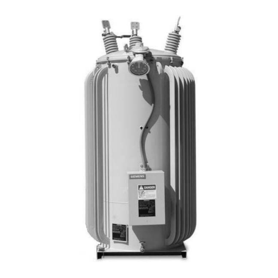
- Page 1 Installation / Operation / Maintenance Instructions 21-115532-001 PR4018-06 SUPERCEDES JFR Distribution 21-115532-001 Step Voltage Regulator PR4018-05 October 08...
-
Page 3: Table Of Contents
COMMITMENT OR RELATIONSHIP. THE SALES CONTRACT CONTAINS THE ENTIRE OBLIGATION OF SIEMENS ENERGY, INC. THE WARRANTY CONTAINED IN THE CONTRACT BETWEEN THE PARTIES IS THE SOLE WARRANTY OF SIEMENS ENERGY, INC. ANY STATEMENTS CONTAINED HEREIN DO NOT CREATE NEW WARRANTIES OR MODIFY THE EXISTING WARRANTY. - Page 5 INTRODUCTION Page 1 Type JFR single-phase step-voltage regulators are designed Q U A L I F I E D P E R S O N to give dependable service and to make installation, operation and maintenance as simple as possible. FOR THE PURPOSE OF THIS MANUAL AND PRODUCT Technology advances, especially in the realm of the control LABELS, A QUALIFIED PERSON IS ONE WHO IS FAMILIAR...
-
Page 6: Introduction
Any damage or shortage that is not noted on the freight bill becomes the recipients responsibility. A claim should be made immediately with the carrier. Please also notify your Siemens representative as soon as possible. -
Page 7: Physical Considerations
INTRODUCTION Page 3 LINE TERMINALS AND PHYSICAL CONSIDERATIONS CONNECTIONS • Handling. Type JFR regulators are designed to be lifted either by a forklift at the base or by use of lifting hooks Type JFR voltage regulators are routinely equipped with line on the side of each tank. -
Page 8: Installation Diagrams
INTRODUCTION Page 4 INSTALLATION DIAGRAMS Open Delta Single Phase Connection of one single phase JFR regulator on single phase line. Connection of two single phase JFR regulators in open delta on a three phase, ungrounded line. Wye Connected Closed Delta Connection of three JFR regulators in closed Connection of three single phase JFR regulators in delta on three phase, ungrounded system. -
Page 9: Protective Measures
INTRODUCTION Page 5 PROTECTIVE MEASURES Bypass Arrester. All JFR regulators are equipped with a properly sized arrester, connected externally between the 'S' and 'L' line terminals. The arrester is provided to protect the series winding of the regulator from line surges. By itself, the bypass arrester does not provide lightning protection for the regulator. -
Page 10: Connection Diagrams
CONNECTION DIAGRAMS Page 6 STRAIGHT DESIGN (ANSI TYPE A) Wiring diagram of a typical Type “A” regulator showing both internal and external connections without fan power. SOURCE LOAD Schematic diagram of a typical Type “A” JFR regulator with fan Typical arrangement of windings and connections of power circuit U3-U5. -
Page 11: Inverted Design
CONNECTION DIAGRAMS Page 7 INVERTED DESIGN (ANSI TYPE B) Wiring diagram of a typical Type “B” regulator showing both internal and external connections. SOURCE LOAD Typical arrangement of windings and connections of Type “B” JFR regulators. Note: Inverted design units may or may not be equiped with a balance winding. -
Page 12: Series Transformers Design
CONNECTION DIAGRAMS Page 8 SERIES TRANSFORMER DESIGN Wiring diagram of a typical regulator with series transformer showing both internal and external connections. SOURCE LOAD Schematic diagram of a typical regulator with series Typical arrangement of windings and connections of transformer with fan power U3-U5. Series JFR regulators, without fan power. -
Page 13: Placing The Regulator In Service
PLACING THE REGULATOR IN SERVICE Page 9 The following checks will be useful in assuring the regulator is ready for use. The list cannot be all inclusive; careful at- tention on the part of a qualified operator remains imperative. Improper By-Pass operation will result in explosion and fire hazard. -
Page 14: Removing The Regulator From Service
REMOVING THE REGULATOR FROM SERVICE Page 10 SWITCHING “OFF LINE” • Improper by-pass operation will result in explosion and Improper By-Pass operation will result fire hazard. Will cause serious injury, death or in explosion and fire hazard. equipment damage. Will cause serious injury, death or •... -
Page 15: Maintenance
Use pressure relief valve to vent regulator before damage. untanking. To prevent: Follow all safety instructions contained herein, and contact your local Siemens sales representative for replacement parts. -
Page 16: Periodic Inspection
If cover top cap is removed, make certain the cap is properly To prevent: sealed when replaced on cover. Siemens recommends applying pipe sealant (Loctite PST or equivalent) around the threads of the Always de-energize and ground the equipment before adapter. -
Page 17: Special Features
SPECIAL FEATURES Page 13 POLARIZED DISCONNECT SWITCH VARI-AMP POSITION INDICATOR (JACK PLUG) AND HINGED CONTROL PANEL The Vari-Amp feature provides a method of operating the regulator at increased load by decreasing the range of op- The Accu/Stat control panel is hinged and may be re- eration. -
Page 18: Operation At Less Than Rated Voltage
SPECIAL FEATURES Page 14 OPERATION AT LESS THAN VARI-AMP RANGE AND CURRENT RATINGS AVAILABLE RATED VOLTAGE ±10% ±8 3/4% ±7 1/2% ±6 1/4% ±5% 10-02.5-050.0 10-02.5-075.0 10-02.5-100.0 JFR regulators may be operated at less 10-02.5-167.0 than the voltage for which they were de- 10-02.5-250.0 1000 1000... -
Page 19: Forced Air Cooling
SPECIAL FEATURES Page 15 SUBBASE ASSEMBLY FORCED AIR COOLING Certain regulators may be equipped for forced-air cooling and include fans mounted on the radiators. The fans are usually Subbase assemblies are available in 4-inch high increments automatically controlled by means of the change in oil from 21 through 49 inches for most JFR regulators. -
Page 20: Parts List
PARTS LIST Page 16 MAJOR COMPONENTS PARTS LIST Instructions For Ordering Part When ordering parts give the quantity of parts required, the regulator serial number, parts list item number, complete description, and method of shipping. State whether for emergency repair, maintenance, spare part, etc. All shipments will be made F.O.B Factory Item Description... -
Page 21: Type Tlg Dial Switch
PARTS LIST Page 17 TYPE TLG DIAL SWITCH Item Item Description Description 01-11 01-11 5328A Reversing Switch Finger Assembly 5320 Panel 5328B Reversing Switch Hub Finger Assembly 5317A Reversing Main Shaft 5329 Drive Arm 5321 Main Stationary Contacts 5330 Hub Finger Support 5322 Reversing Stationary Contact R 5331... -
Page 22: Type Tlg Quick Break Mechanism
PARTS LIST Page 18 TYPE TLG QUICK BREAK MECHANISM Item Item Description Description 01-11 01-11 5201G Mounting Frame Assembly 5238 Reversing Switch Assembly 5202 Motor 5240 Spring 5207 Drive Spring Assembly 5241 Spring Tube 5212 Latch Assembly 5242 Position Indicator Drive Mechanism 5213 Latch Spring (not shown) 5243A... -
Page 23: Type Tlf Dial Switch
PARTS LIST Page 19 TYPE TLF DIAL SWITCH FIGURE 20A Item Item Description Description 01-11 01-11 5351 Panel 5363 Drive Plate 5352 Stationary Contact 5364 Contact Finger Assembly - Rev. Switch 5353 Neutral Stationary Contact 5365 Contact Support Assembly 5354 Stationary Contact - LH 5366 Reversing Drive Pin... -
Page 24: Type Tlf Quick Break Mechanism
PARTS LIST Page 20 TYPE TLF QUICK BREAK MECHANISM Figure 21A Item Item Description Description 01-11 01-11 5266 Interlock Disc and Drive Sprocket Assembly 5233A Counter Switch Assembly 5267 Quick Break Mechanism Shaft 5243B Neutral Switch 5275 Actuating Arm Assembly 5251 Mounting Frame 5276... -
Page 25: Bypass Arresters
PARTS LIST Page 21 BYPASS ARRESTERS I t e m D e s c r i p t i o n V o l t s 0 1 - 1 1 5423 B y p a s s A r r e s t e r A s s e m b l y 3 k V M O V 2 , 5 0 0 , 5 , 0 0 0 , 7 , 6 2 0 5 4 2 5 M o u n t i n g B r a c k e t A s s e m b l y... -
Page 26: Bushings
PARTS LIST Page 22 BUSHINGS Item Description Volts 01-11 5400P Bushing Assembly for 15 kV 5000 38.1 thru 76.2 7620 69 thru 138 13,800 5400R Bushing Assembly for 15 kV 2500 5000 114.3 thru 167 7620 5400S Bushing Assembly for 15 kV 2500 13,800 5401P... - Page 27 PARTS LIST Page 23 BUSHINGS Item Description Volts 01-11 5400T Bushing Assembly 15 kV 100 thru 167 2500 250 thru 509 7620 5400U Bushing Assembly, 15 kV 207-276 13,800 5400V Bushing Assembly, 23 kV 72 thru 144 14,400 100 thru 200 19,920 5400W Bushing Assembly 15 kV...
- Page 28 Siemens Energy, Inc. P.O. Box 6289 Jackson, MS 39288-6289 Phone: 601-939-0550 Fax: 601-939-3606 ACCU/STAT, DATA/PAK, NEUTRALITE and VARI- AMP are trademarks of Siemens Energy, Inc. PR4018-06 PR4018-05 PR4018-04 October 08 PRINTED IN U.S.A.