Table of Contents
Advertisement
Advertisement
Table of Contents

Related Manuals for D-Link DGS-3620-28SC-EI


Summary of Contents for D-Link DGS-3620-28SC-EI
- Page 2 Information in this document is subject to change without notice. Reproduction in any manner whatsoever, without the written permission of D-Link Corporation, is strictly forbidden. Trademarks used in this text: D-Link and the D-LINK logo are trademarks of D-Link Corporation; Microsoft and Windows are registered trademarks of Microsoft Corporation.
-
Page 3: Table Of Contents
® xStack DGS-3620 Series Layer 3 Managed Stackable Gigabit Switch Hardware Installation Guide Table of Contents Intended Readers ................................v Typographical Conventions ............................v Notes, Notices, and Cautions ............................v Safety Instructions ................................. vi Safety Cautions ................................vi General Precautions for Rack-Mountable Products ...................... vii Protecting Against Electrostatic Discharge ........................ - Page 4 ® xStack DGS-3620 Series Layer 3 Managed Stackable Gigabit Switch Hardware Installation Guide Appendix Section ................................42 Appendix A – Technical Specifications ........................42 General ..................................42 Physical and Environmental............................42 Performance................................43 Port Functions ................................44 Appendix B – Cables and Connectors ......................... 45 Ethernet Cable ................................
-
Page 5: Intended Readers
® xStack DGS-3620 Series Layer 3 Managed Stackable Gigabit Switch Hardware Installation Guide Intended Readers Typographical Conventions Notes, Notices, and Cautions Safety Instructions The DGS-3620 Series Hardware Installation Guide contains information for the setup and management of the DGS- 3620 Series Switches. This manual is intended for network managers familiar with network management concepts and terminology. -
Page 6: Safety Instructions
® xStack DGS-3620 Series Layer 3 Managed Stackable Gigabit Switch Hardware Installation Guide Safety Instructions Use the following safety guidelines to ensure your own personal safety and to help protect your system from potential damage. Throughout this safety section, the caution icon ( ) is used to indicate precautions that need to be reviewed and followed. -
Page 7: General Precautions For Rack-Mountable Products
® xStack DGS-3620 Series Layer 3 Managed Stackable Gigabit Switch Hardware Installation Guide Position system cables and power cables carefully; route cables so that they cannot be stepped on or tripped over. Be sure that nothing rests on any cables. ... -
Page 8: Protecting Against Electrostatic Discharge
® xStack DGS-3620 Series Layer 3 Managed Stackable Gigabit Switch Hardware Installation Guide Protecting Against Electrostatic Discharge Static electricity can harm delicate components inside the system. To prevent static damage, discharge static electricity from your body before touching any of the electronic components, such as the microprocessor. This can be done by periodically touching an unpainted metal surface on the chassis. -
Page 9: Chapter 1 Introduction
- DEM-315GT (1000BASE-ZX, Single-mode, 80km) - DEM-330T/R (1000BASE-BX, WDM transceiver, Single-Mode 10km) - DEM-331T/R (1000BASE-BX, WDM transceiver, Single-Mode 40km) D-Link provides the following direct attached cables for stacking or short distance connections: - DEM-CB100S-10-GbE SFP+1m Direct Attach Cable - DEM-CB300S-10-GbE SFP+3m Direct Attach Cable... -
Page 10: Features
® xStack DGS-3620 Series Layer 3 Managed Stackable Gigabit Switch Hardware Installation Guide Features The list of features below highlights the significant features of the Switch. IEEE 802.3 compliant IEEE 802.3z compliant IEEE 802.3x Flow Control in full-duplex compliant ... -
Page 11: Ports
® xStack DGS-3620 Series Layer 3 Managed Stackable Gigabit Switch Hardware Installation Guide RFC 1213 MIB II RFC 4188 Bridge RFC 1907 SNMPv2 RFC 2819 RMON RFC 2665 Ether-like MIB RFC 2863 IF MIB RFC 2618 RADIUS Authentication Client MIB RFC 2620 RADIUS Accounting Client MIB Private MIB RFC 4363 for 802.1p MIB... -
Page 12: Front-Panel Components
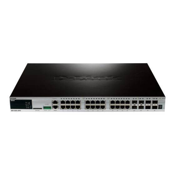
® xStack DGS-3620 Series Layer 3 Managed Stackable Gigabit Switch Hardware Installation Guide Front-Panel Components The front panel of the DGS-3620 Series consists of the Management and Console port, LED indicators for Power, Console, and stacking ID LED’s. A separate table below describes LED indicators in more detail. DGS-3620-28TC Figure 1–1 Front panel view of a DGS-3620-28TCSwitch ... - Page 13 ® xStack DGS-3620 Series Layer 3 Managed Stackable Gigabit Switch Hardware Installation Guide SD Card slot 2 Digital in and 1 Digital out Alarm connector LEDs for Power, Console, RPS, SD card slot, MGMT, and Link/Act/Speed for each port ...
- Page 14 ® xStack DGS-3620 Series Layer 3 Managed Stackable Gigabit Switch Hardware Installation Guide Figure 1–7 Front panel view of a DGS-3620-52P Switch Forty-eight 10/100/1000 PoE+ Base-T Four SFP+ ports LEDs for Power, Console,RPS, SD card slot, PoE, MGMT and Link/Act/Speed for each port NOTE: The alarm PIN’s 1,2 and 3 works under 60V while pins 4,5,6, and 7 works under 3V CAUTION: The alarm port on the DGS-3620 Series is provided to trigger external events that may affect the switch.
- Page 15 ® xStack DGS-3620 Series Layer 3 Managed Stackable Gigabit Switch Hardware Installation Guide LED Indicators The DGS-3620 Series front panel presents LED indicators for Power, Console, RPS, Master (stack control), Stack ID and Link/Act indicators for all ports including the Gigabit Ethernet ports. Location LED Indicators Color...
- Page 16 ® xStack DGS-3620 Series Layer 3 Managed Stackable Gigabit Switch Hardware Installation Guide ports. Orange Solid light When there is a secure connection (or link) to 10/100Mbps Ethernet device at any of the ports. Blinking When there is a secure connection (or link) to 10/100Mbps Ethernet device at any of the ports.
-
Page 17: Led Panel Indicators Part Ii
® xStack DGS-3620 Series Layer 3 Managed Stackable Gigabit Switch Hardware Installation Guide LED Panel Indicators Part II DGS-3620-28TC LED Panel = Power, Console, RPS, SD Card, Management Figure 2-1 LED indicators for a DGS-3620-28TC Switch DGS-3620-28TC-DC LED Panel = Power, Console, SD Card, Management Figure 2-2 LED indicators for a DGS-3620-28TC-DC Switch DGS-3620-28SC LED Panel = Power, Console, RPS, SD Card, Management Figure 2-3 LED indicators for a DGS-3620-28SC Series Switch... - Page 18 ® xStack DGS-3620 Series Layer 3 Managed Stackable Gigabit Switch Hardware Installation Guide Figure 2-4 LED indicators for a DGS-3620-28SC-DC Switch DGS-3620-28PC LED Panel = Power, Console, RPS, SD Card, LINK/ACT/SPD, POE, Management Figure 2-5 LED indicators for a DGS-3620-28PC Switch DGS-3620-52T LED Panel = Power, Console, RPS, SD Card, Management Figure 2-6 LED indicators for a DGS-3620-52T Switch DGS-3620-52P LED Panel = Power, Console, RPS, SD Card, LINK/ACT/SPD, POE, Management...
- Page 19 ® xStack DGS-3620 Series Layer 3 Managed Stackable Gigabit Switch Hardware Installation Guide Figure 2-7 LED indicators for a DGS-3620-52P Switch...
-
Page 20: Rear Panel Description
® xStack DGS-3620 Series Layer 3 Managed Stackable Gigabit Switch Hardware Installation Guide Rear Panel Description The rear panel of the DGS-3620 Series Switches contains an AC/DC power connector the Redundant Power Supply connector. Here are illustrations of a selection of devices. DGS-3620-28TC Figure 3-1 Rear panel view of a DGS-3620-28TC Switch On the left side of the DGS-3620-28TC is a standard AC power connector. - Page 21 ® xStack DGS-3620 Series Layer 3 Managed Stackable Gigabit Switch Hardware Installation Guide NOTE: The DGS-3620-28TC-DC does not support the Redundant Power Supply function even though it has the device on the back-panel. DGS-3620-28PC Figure 3-5 Rear panel view of a DGS-3620-28PC Switch On the left side of the DGS-3620-28PC is a standard AC power connector.
-
Page 22: Side Panel Description
® xStack DGS-3620 Series Layer 3 Managed Stackable Gigabit Switch Hardware Installation Guide Side Panel Description The system heat vents located on the sides of the DGS-3620-Series of switches dissipate heat. Do not block these openings. Leave at least 6 inches of space at the rear and sides of the Switch for proper ventilation. Without proper heat dissipation and air circulation, system components might overheat which could lead to system failure or even severely damaged components. -
Page 23: Chapter 2 Installation
One CD kit for CLI reference guide/Web UI reference guide/Hardware Installation Guide/D-View module If any item is missing or damaged, please contact your local D-Link Reseller for replacement. Installation Guidelines Please follow these guidelines for setting up the Switch: ... -
Page 24: Installing The Switch Without A Rack
® xStack DGS-3620 Series Layer 3 Managed Stackable Gigabit Switch Hardware Installation Guide Installing the Switch without a Rack First, attach the rubber feet included with the Switch if installing on a desktop or shelf. Attach these cushioning feet on the bottom at each corner of the device. -
Page 25: Mounting The Switch In A Standard 19" Rack
® xStack DGS-3620 Series Layer 3 Managed Stackable Gigabit Switch Hardware Installation Guide Mounting the Switch in a Standard 19" Rack Figure 2–3 Mount the switch in a rack Power On 1. Plug one end of the AC power cord into the power connector of the Switch and the other end into the local power source outlet. -
Page 26: Installing Sfp And Sfp+ Ports
® xStack DGS-3620 Series Layer 3 Managed Stackable Gigabit Switch Hardware Installation Guide Installing SFP and SFP+ Ports The Switch is equipped with SFP (Small Form Factor Portable) and SFP+ ports, which are used with fiber-optical transceiver cabling.SFP ports support full-duplex transmissions, auto-negotiation, and can be uplinked with various other switches across a gigabit network. - Page 27 ® xStack DGS-3620 Series Layer 3 Managed Stackable Gigabit Switch Hardware Installation Guide Figure 2–4 Inserting fiber-optic transceivers into a DGS-3620 Series Switch...
-
Page 28: Connecting To A Redundant Power Supply
® xStack DGS-3620 Series Layer 3 Managed Stackable Gigabit Switch Hardware Installation Guide Connecting to a Redundant Power Supply The DGS 3620 Series switch connects to the Master Switch using a 14-pin DC power cable. A standard, three- pronged AC power cable connects the redundant power supply to the main power source. Figure 2–5 Connecting a DGS-3620 Series Switch to the DPS-500 (28SC, 28TC, 52T) 1. -
Page 29: External Redundant Power System
® xStack DGS-3620 Series Layer 3 Managed Stackable Gigabit Switch Hardware Installation Guide External Redundant Power System The DPS-500/700 is a redundant power-supply unit designed to conform to the voltage requirements of the switches being supported. The DPS-500/700 can be installed into a DPS-900, or DPS-800 rack mount unit. CAUTION: DO NOT connect the RPS to AC power before the DC power cable is connected. -
Page 30: Dps-800
® xStack DGS-3620 Series Layer 3 Managed Stackable Gigabit Switch Hardware Installation Guide Figure 2–7 Install the DPS-900 into the equipment rack CAUTION: Installing systems in a rack without the front and side stabilizers installed could cause the rack to tip over, potentially resulting in bodily injury under certain circumstances. Therefore, always install the stabilizers before installing components in the rack. - Page 31 ® xStack DGS-3620 Series Layer 3 Managed Stackable Gigabit Switch Hardware Installation Guide Figure 2–8 Install the DPS-500 in the DPS-800 The RPS can be mounted in a standard 19" rack. Use the following diagram to guide you. Figure 2–9 Install the DPS-800 in an Equipment Rack...
-
Page 32: Chapter 3 Connecting The Switch
® xStack DGS-3620 Series Layer 3 Managed Stackable Gigabit Switch Hardware Installation Guide Chapter 3 Connecting the Switch Switch to End Node Switch to Switch Connecting To Network Backbone or Server Note: All high-performance N-Way Ethernet ports can support both MDI-II and MDI-X connections. Switch to End Node End nodes include PCs outfitted with a 10/100/1000 Mbps RJ-45 Ethernet Network Interface Card (NIC) and routers. -
Page 33: Connect To A Network Backbone Or Server
® xStack DGS-3620 Series Layer 3 Managed Stackable Gigabit Switch Hardware Installation Guide Figure 3–2 Connect the Switch to a port on a switch with a straight or crossover cable Connect to a Network Backbone or Server The combo SFP ports and the 1000BASE-T ports are ideal for uplinking to a network backbone, server or server farm. The copper ports operate at a speed of 10/100/1000Mbps in half or full duplex mode. -
Page 34: Chapter 4 Introduction To Switch Management
® xStack DGS-3620 Series Layer 3 Managed Stackable Gigabit Switch Hardware Installation Guide Chapter 4 Introduction to Switch Management Management Options Connecting the Console Port (RS-232 DCE/RJ-45) First Time Connecting to the Switch Password Protection SNMP Settings IP Address Assignment Management Options This system may be managed out-of-band through the console port on the front panel or in-band using Telnet. - Page 35 ® xStack DGS-3620 Series Layer 3 Managed Stackable Gigabit Switch Hardware Installation Guide Note: When using HyperTerminal with the Microsoft® Windows® 2000 operating system, ensure that Windows 2000 Service Pack 2 or later is installed. Windows 2000 Service Pack 2 allows the use of arrow keys in HyperTerminal's VT100 emulation.
-
Page 36: Connecting To The Switch For The First Time
Once you have connected to the DGS-3620 Series Switch, the following screen appears (see Figure 4-2). DGS-3620-28SC Gigabit Ethernet Switch Command Line Interface Firmware: Build 2.00.015 Copyright(C) 2012 D-Link Corporation. All rights reserved. UserName: Figure 4–2 Initial screen, first time connecting to the Switch ... -
Page 37: Password Protection
® xStack DGS-3620 Series Layer 3 Managed Stackable Gigabit Switch Hardware Installation Guide Password Protection The DGS-3620 Series Switches do not have a default user name and password. One of the first tasks when settings up the Switch is to create user accounts. Logging in using a predefined administrator-level user name will give the user privileged access to the Switch's management software. -
Page 38: Traps
® xStack DGS-3620 Series Layer 3 Managed Stackable Gigabit Switch Hardware Installation Guide In SNMP v1 and v2, user authentication is accomplished using 'community strings', which function like passwords. The remote user SNMP application and the Switch SNMP must use the same community string. SNMP packets from any station that has not been authenticated are ignored (dropped). -
Page 39: Chapter 5 Web-Based Switch Configuration
® xStack DGS-3620 Series Layer 3 Managed Stackable Gigabit Switch Hardware Installation Guide Chapter 5 Web-based Switch Configuration Introduction Logging onto the Web Manager Web-based User Interface Introduction All software functions of the Switch can be managed, configured, and monitored via the embedded web-based (HTML) interface. -
Page 40: Web-Based User Interface
Switch's ports and expansion modules and shows port activity, depending on the specified mode. Some management functions, including port monitoring are accessible here. Click the D-Link logo to go to the D-Link Website. AREA 3 Presents Switch status based on user selection and the entry of configuration data. In... -
Page 41: Web Pages
® xStack DGS-3620 Series Layer 3 Managed Stackable Gigabit Switch Hardware Installation Guide Web Pages When connecting to the management mode of the Switch with a Web browser, a login screen is displayed. Enter a user name and password to access the Switch's management mode. Note: Be sure to configure the user name and password in the User Accounts window before connecting the Switch to the greater network. -
Page 42: Appendix Section
® xStack DGS-3620 Series Layer 3 Managed Stackable Gigabit Switch Hardware Installation Guide Appendix Appendix A – Technical Specifications General Feature Detailed Description IEEE 802.3 compliance Standards IEEE 802.3u compliance Support Full-Duplex operations IEEE 802.3x Flow Control support for Full-Duplex mode IEEE 802.3ab compliance IEEE 802.3af compliance (DGS-3620-28PC &... -
Page 43: Performance
® xStack DGS-3620 Series Layer 3 Managed Stackable Gigabit Switch Hardware Installation Guide DGS-3620-52P=505.4W Operating Temperature 0~50°C Storage Temperature -40~70°C MTBF DGS-3620-28TC = 287763.2892 Hours DGS-3620-28TC-DC = 372899.3973 Hours DGS-3620-28SC = 299801.4971 Hours DGS-3620-28SC-DC = 393367.7595 Hours DGS-3620-28PC = 230619.6475 Hours DGS-3620-52T = 255608.808 Hours DGS-3620-52P = 202462.1368 Hours Humidity... -
Page 44: Port Functions
® xStack DGS-3620 Series Layer 3 Managed Stackable Gigabit Switch Hardware Installation Guide DGS-3620-28PC:128Gbps DGS-3620-52T:176Gbps DGS-3620-52P:176Gbps 64 Byte System Packet DGS-3620-28TC/28TC-DC:95.24Mpps Forwarding Rate DGS-3620-28SC/28SC-DC:95.24Mpps DGS-3620-28PC:95.24Mpps DGS-3620-52T:130.95Mpps DGS-3620-52P:130.95Mpps Priority Queues 8 Priority Queues per port MAC Address Table Supports 32K MAC address Supports 256 static MAC Port Functions Feature... -
Page 45: Appendix B - Cables And Connectors
8 wires. Use CAT3 ~ 6A UTP cable for 802.3af or CAT5e~ 6A UTP cable for 802.3at 9. DGS-3620-28PC, DGS-3620-52P works with all D-Link 802.3af and 802.3at capable devices, and works with all non-802.3af and non-802.3at capable D-Link Access Points, IP Cams and IP phones via the DWL-P50. SFP+ Transceivers Supported: 10G Ports - DEM-431XT:10GBASE-SR SFP+ Transceiver 80m: OM1 &... -
Page 46: Console Cable
® xStack DGS-3620 Series Layer 3 Managed Stackable Gigabit Switch Hardware Installation Guide Figure 5–3 Standard RJ-45 port and connector RJ-45 Pin Assignments MDI-X Port MDI-II Port RD+ (receive) TD+ (transmit) RD- (receive) TD- (transmit) TD+ (transmit) RD+ (receive) 1000BASE-T 1000BASE-T 1000BASE-T 1000BASE-T... -
Page 47: Redundant Power Supply (Rps) Cable
® xStack DGS-3620 Series Layer 3 Managed Stackable Gigabit Switch Hardware Installation Guide Not Used GND (shared) Not Used Not Used Not Used Not Used Not Used Redundant Power Supply (RPS) Cable When connecting the Switch to a Redundant Power Supply, an RPS cable is necessary. Please review these products for matching cable pins.The following diagrams and tables show the standard RPS connector and their pin assignments. - Page 48 ® xStack DGS-3620 Series Layer 3 Managed Stackable Gigabit Switch Hardware Installation Guide RPS Cable Pin Assignments Device DPS-700 -54Vrtn -54Vrtn -54V -54V +12V +12V +12V +12V +12V +12V +12V +12V NC/GND NC/GND +12vsen +12Ven LS-54v LS-54V -54V -54V -54Vrtn -54Vrtn GND/NC GND/NC...
- Page 49 The customer must submit with the product as part of the claim a written description of the Hardware defect or Software nonconformance in sufficient detail to allow D-Link to confirm the same, along with proof of purchase of the product (such as a copy of the dated purchase invoice for the product).
- Page 50 D-Link Corporation/D-Link Systems, Inc., as stipulated by the United States Copyright Act of 1976 and any amendments thereto. Contents are subject to change without prior notice. Copyright 2009 by D-Link Corporation/D-Link Systems, Inc.
-
Page 51: Product Registration
Product Registration Register your D-Link product online at http://support.dlink.com/register/ Product registration is entirely voluntary and failure to complete or return this form will not diminish your warranty rights. -
Page 52: Tech Support
You can find software updates and user documentation on the D- Link website. D-Link provides free technical support for customers within the United States and within Canada for the duration of the service period, and warranty confirmation service, during the warranty period on this product. -
Page 53: Technical Support
Technical Support United Kingdom (Mon-Fri) Home Wireless/Broadband 0871 873 3000 (9.00am–06.00pm, Sat 10.00am-02.00pm) Managed, Smart, & Wireless Switches, or Firewalls 0871 873 0909 (09.00am – 05.30pm) (BT 10ppm, other carriers may vary.) Ireland (Mon-Fri) All Products 1890 886 899 (09.00am-06.00pm, Sat 10.00am-02.00pm) €0.05ppm peak, €0.045ppm off peak Times Internet http://www.dlink.co.uk... -
Page 54: Assistance Technique
Assistance technique Assistance technique D-Link sur internet :http://www.dlink.fr Assistance technique D-Link par téléphone : 01 76 54 84 17 Du lundi au vendredi de 9h à 19h (hors jours fériés) Asistencia Técnica Asistencia Técnica Telefónica de D-Link: +34 902 30 45 45 0,067 €/min... -
Page 55: Pomoc Techniczna
Pomoc techniczna Telefoniczna pomoc techniczna firmy D-Link: 0 801 022 021 Pomoc techniczna firmy D-Link świadczona przez Internet: http://www.dlink.eu/support/ Technická podpora Web: http://www.dlink.cz/support/ E-mail: support@dlink.cz Telefon ČR: +420 211 151 640 nebo SK: +421 (0)692 147 110 Telefonická podpora je v provozu: PO - PÁ od 09:00 do 17:00 Volání... - Page 56 Internetin kautta : http://www.dlink.fi Arkisin klo. 09:00 - 18: 00 Numerosta : 0200-555 57 Teknisk Support D-Link Teknisk Support via Internet: http://www.dlink.se D-Link Teknisk Support via telefon: 0770-33 00 35 Vardagar 08:00 - 17:00 Assistência Técnica Assistência Técnica da D-Link na Internet: http://www.dlink.pt e-mail: soporte@dlink.es...
- Page 57 D-Link - ovo spletno stran www.dlink.eu www.dlink.biz/sl Suport tehnic Vă mulţumim pentru alegerea produselor D-Link. Pentru mai multe informaţii, suport şi manuale ale produselor vă rugăm să vizitaţi site-ul D-Link www.dlink.eu www.dlink.ro...
- Page 58 Technical Support You can find software updates and user documentation on the D-Link website. Tech Support for customers in Australia: D-Link Middle East - Dubai, U.A.E. Tel: 1300-766-868 Plot No. S31102, 24/7 Technical Support Jebel Ali Free Zone South, Web: http://www.dlink.com.au P.O.Box 18224, Dubai, U.A.E.
- Page 59 Technical Support You can find software updates and user documentation on the D-Link website. Tech Support for customers in Iran Israel Unit 5, 5th Floor, No. 20, 17th Alley , Bokharest המגשימים רח St. , Argentine Sq. , 49348 ת...
- Page 60 Техническая поддержка Обновления программного обеспечения и документация доступны на Интернет-сайте D-Link. D-Link предоставляет бесплатную поддержку для клиентов в течение гарантийного срока. Клиенты могут обратиться в группу технической поддержки D-Link по телефону или через Интернет. Техническая поддержка D-Link: +7(495) 744-00-99 Техническая поддержка через Интернет...
- Page 61 SOPORTE TÉCNICO Usted puede encontrar actualizaciones de softwares o firmwares y documentación para usuarios a través de nuestro sitio www.dlinkla.com SOPORTE TÉCNICO PARA USUARIOS EN LATINO AMERICA Soporte técnico a través de los siguientes teléfonos de D-Link PAIS NUMERO Argentina...
- Page 62 Suporte Técnico Caso tenha dúvidas na instalação do produto, entre em contato com o Suporte Técnico D-Link por: Chat Online www.dlink.com.br/suporte E-mail suporte@dlink.com.br Back Office backoffice@dlink.com.br *Acionar Garantia para 4 ou mais equipamentos Telefones São Paulo: (11) 2755-6950 *GO: 4052-1850 (Ligação local) *Nordeste: 0800-7024104 *Demais Estados: 4062-1850 (Ligação local)
- Page 63 D-Link D-Link...
- Page 64 Dukungan Teknis Update perangkat lunak dan dokumentasi pengguna dapat diperoleh pada situs web D-Link. Dukungan Teknis untuk pelanggan: Dukungan Teknis D-Link melalui telepon: Tel: +62-21-5731610 Dukungan Teknis D-Link melalui Internet: Email : support@dlink.co.id Website : http://support.dlink.co.id...
- Page 65 Technical Support この度は弊社製品をお買い上げいただき、誠にありがとうご ざいます。 下記弊社 Web サイトからユーザ登録及び新製品登録を 行っていただき、ダウンロードサービスにて サポート情報、ファームウェア、ユーザマニュアルを ダウンロードすることができます。 ディーリンクジャパン Web サイト URL:http://www.dlink-jp.com...
- Page 66 技术支持 办公地址:北京市东城区北三环东路 36 号 环球贸易中心 B 座 26F 02-05 室 邮编: 100013 技术支持中心电话:8008296688/ (028)66052968 技术支持中心传真:(028) 87300889 各地维修中心地址请登陆官方网站查询 网址:http://www.dlink.com.cn 办公时间:周一到周五,早09:00到晚18:00...
-
Page 67: Registration Card
8. What category best describes your company? Aerospace Engineering Education Finance Hospital Legal Insurance/Real Estate Manufacturing Retail/Chain store/Wholesale Government Transportation/Utilities/Communication System house/company Other________________________________ 9. Would you recommend your D-Link product to a friend? Don't know yet 10.Your comments on this product? __________________________________________________________________________________________ __________________________________________________________________________________________...