Panasonic KV-S2045C Service Manual
High speed color scanner kv-s2025c series; kv-su225c series; kv-s2045c series; kv-su245c series
Hide thumbs
Also See for KV-S2045C:
- Operating instructions manual (42 pages) ,
- Maintenance manual (2 pages)
Table of Contents
Advertisement
Quick Links
Advertisement
Table of Contents

Related Manuals for Panasonic KV-S2045C


Summary of Contents for Panasonic KV-S2045C
- Page 1 ORDER NO. KM70206776C0 High Speed Color Scanner KV-S2025C Series KV-SU225C Series KV-S2045C Series KV-SU245C Series © 2002 Kyushu Matsushita Electric Co., Ltd. All rights reserved. Unauthorized copying and distribution is a violation of law.
-
Page 2: Table Of Contents
KV-S2025C Series / KV-SU225C Series / KV-S2045C Series / KV-SU245C Series CONTENTS Page Page 1 GENERAL PRECAUTIONS 10.1. Troubleshooting -1 (with no error message on PC) 1.1. Safety Precautions 10.2. Troubleshooting -2 (according to Error Code or Scanner 1.2. Electrical Tests Status in Service Utility) 1.3. -
Page 3: General Precautions
KV-S2025C Series / KV-SU225C Series / KV-S2045C Series / KV-SU245C Series 1 GENERAL PRECAUTIONS 1.1. Safety Precautions 1. Before servicing, unplug the power cord to prevent electrical shock hazard. 2. When replacing parts, user only manufacture’s recommended components for safety. -
Page 4: About Lead Free Solder (Pbf: Pb Free)
KV-S2025C Series / KV-SU225C Series / KV-S2045C Series / KV-SU245C Series 1.4. About Lead Free Solder (PbF: Pb free) Note · In the information below, Pb, the symbol for lead in the periodic table of elements, will refer to standard solder or solder that contains lead. -
Page 5: Specifications
Humidity: 10% to 80%RH Accessories Power cord, Feed extension tray (Only for KV-S2045C Series), Exit extension tray (Only for KV- S2045C Series), Roller cleaning paper, CD ROM (Maintenance, Safety and Installation manual, Operation instructions, RTIV Capture software, ISIS driver, TWAIN driver, PIE manual, RTIV manual,... -
Page 6: Kv-Su225C/Su245C Series
KV-S2025C Series / KV-SU225C Series / KV-S2045C Series / KV-SU245C Series Note · *1: These values (Readout speed) depend on the test environment. The test environment by Manufacturer KME is as follows. PC Environment ® ® OS: Windows NT 4.0 / CPU: Pentium 300MHz / Amount of Memory: 256MB / SCSI Card: 2940AU / Software: Twain 1.00... -
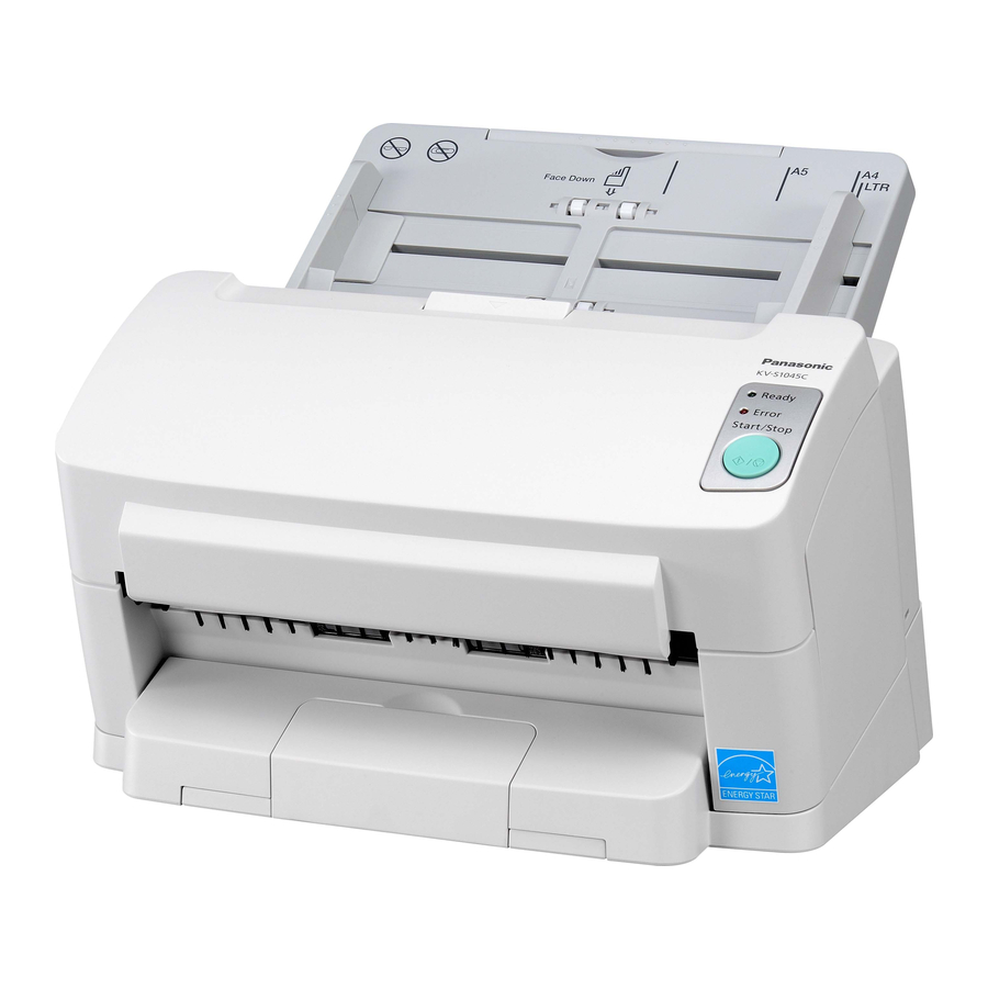
Page 7: Component Identification
KV-S2025C Series / KV-SU225C Series / KV-S2045C Series / KV-SU245C Series 3 COMPONENT IDENTIFICATION Imprinter Door Document Guide Paper Feed Case ADF Door ADF Door Release Feed Tray Feed Extension Tray STOP / START Button Exit Tray Business Card Guide... -
Page 8: Installation
KV-S2025C Series / KV-SU225C Series / KV-S2045C Series / KV-SU245C Series 4 INSTALLATION 4.1. Minimum Space Requirements Be sure to maintain the recommended space requirements for proper ventilation. 4.2. Installing Feed Extension Tray and Exit Extension Tray (Only for KV- S2045C/SU245C Series) Take out the Feed Extension Tray and Exit Extension Tray in the accessory carton box, and install them as shown below. -
Page 9: Connecting The Scanner To A Personal Computer
KV-S2025C Series / KV-SU225C Series / KV-S2045C Series / KV-SU245C Series 4.3. Connecting the Scanner to a Personal Computer 4.3.1. KV-S2025C/S2045C Series Fig. 4.3.1 Note Power Cord shown on the Fig. 4.3.1 is for AC100-120V. Caution 1. Use the Power Cord that is supplied with the scanner manufacturer. -
Page 10: Scsi Setting (Only For Kv-S2025C/S2045C Series)
KV-S2025C Series / KV-SU225C Series / KV-S2045C Series / KV-SU245C Series 4.5. SCSI Setting (Only for KV-S2025C/S2045C Series) Set SCSI ID and Terminator on the DIP Switch whose layout is shown on Fig. 4.5.1. Fig. 4.5.1 4.5.1. SCSI ID Referring to the following Fig. 4.5.2, be sure to set a scanner´s SCSI ID number of the DIP Switch, different from the other SCSI device in the SCSI chain. -
Page 11: Sectional Views
KV-S2025C Series / KV-SU225C Series / KV-S2045C Series / KV-SU245C Series 5 SECTIONAL VIEWS 5.1. CIS (Contact Image Sensor) Imprinter (Option) (KV-S2045C/SU245C Series only) Conveyor Motor CIS (Front) Sensor Roller (Front) CIS (Back) Sensor Roller (Back) Paper Feed Motor... -
Page 12: Rollers
KV-S2025C Series / KV-SU225C Series / KV-S2045C Series / KV-SU245C Series 5.2. Rollers Separation Roller Paper Feed Roller Retard Roller Drive Rollers Exit Roller... -
Page 13: Circuit Boards
KV-S2025C Series / KV-SU225C Series / KV-S2045C Series / KV-SU245C Series 5.3. Circuit Boards RELAY (FRONT) Board RELAY (BACK) Board CONTROL Board LED Board POWER Board POWER SW Board (Power Switch) -
Page 14: Sensor Boards And Switch
KV-S2025C Series / KV-SU225C Series / KV-S2045C Series / KV-SU245C Series 5.4. Sensor Boards and Switch WAITING SENSOR Board (Waiting Sensor) Door Switch Paper Detector STARTING POSITION SENSOR Board (Starting Position Sensor) ENDING SENSOR Board (Ending Sensor) -
Page 15: Mechanical Function
KV-S2025C Series / KV-SU225C Series / KV-S2045C Series / KV-SU245C Series 6 MECHANICAL FUNCTION 6.1. Feed Mechanism for KV-S2025C/SU225C Series 1. Scanning command is issued from PC, Paper detector checks whether documents exist on the Feed Tray. 2. Conveyor Motor is driven to rotate Drive Rollers. -
Page 16: Feed Mechanism For Kv-S2045C/Su245C Series
KV-S2025C Series / KV-SU225C Series / KV-S2045C Series / KV-SU245C Series 6.2. Feed Mechanism for KV-S2045C/SU245C Series 6.2.1. In case the data size of a document is over the amount of the memory in the scanner. Same sequence as the above 6.1. says. -
Page 17: Maintenance
KV-S2025C Series / KV-SU225C Series / KV-S2045C Series / KV-SU245C Series 7 MAINTENANCE 7.1. Maintenance Chart C: Clean R: Replace (×1000 sheets) Description Reference of Part No. 80 - 260 280 300 Paper Feed Roller Ref. No. 52 in Sec.14.3 Clean each part every 20 (×... - Page 18 KV-S2025C Series / KV-SU225C Series / KV-S2045C Series / KV-SU245C Series 7.2.1. Cleaning Paper Feed Roller, Separation Roller, and Retard Roller Turn off the scanner. Push the ADF Door Release to open the ADF Door. Wipe off the dirt on the surfaces of the Paper Feed Roller and Separation Roller with the accessory Roller Cleaning Paper or Model KV-SS03 (Option: Roller Cleaning Paper).
- Page 19 KV-S2025C Series / KV-SU225C Series / KV-S2045C Series / KV-SU245C Series Clean the surface of the Retard Roller with the accessory Roller Cleaning Paper or Model KV-SS03 (Option: Roller Cleaning Paper). When cleaning it, wipe off the dirt on the roller surface all the way around it proceeding from one end to the other in the direction of the arrow shown in the figure.
- Page 20 KV-S2025C Series / KV-SU225C Series / KV-S2045C Series / KV-SU245C Series 7.2.2. Cleaning Driver Rollers and Free Rollers Turn off the scanner. Push the ADF Door Release to open the ADF Door. Wipe off the dirt on the surfaces of the Drive Rollers in the...
- Page 21 KV-S2025C Series / KV-SU225C Series / KV-S2045C Series / KV-SU245C Series Close the ADF Door slowly until it clicks into place. 7.2.3. Cleaning CIS and Sensor Rollers Turn off the scanner. Push the ADF Door Release to open the ADF Door.
- Page 22 KV-S2025C Series / KV-SU225C Series / KV-S2045C Series / KV-SU245C Series Wipe off the glass surface on the CIS (Back) and the Sensor Roller (Front) in the direction of the arrows shown in the figure with the accessory Roller Cleaning Paper or Model KV-SS03 (Option: Roller Cleaning Paper).
- Page 23 KV-S2025C Series / KV-SU225C Series / KV-S2045C Series / KV-SU245C Series 7.2.4. Cleaning Sensors and Reflector Sheets Turn off the scanner. Push the ADF Door Release to open the ADF Door. Sweep out the dirt from the Paper Detector, Waiting Sensor, and Starting Position Sensor with a soft cotton swab.
- Page 24 KV-S2025C Series / KV-SU225C Series / KV-S2045C Series / KV-SU245C Series Close the ADF Door slowly until it clicks into place. 7.2.5. Cleaning Exit Roller, Free Roller, and Ending Sensor Remove the Exit Roller. (See 8.3.8.) Clean the surfaces of the Exit Roller in the direction of the arrows with the accessory Roller Cleaning Paper or Model KV-SS03.
-
Page 25: Replacing Limited Life Parts
KV-S2025C Series / KV-SU225C Series / KV-S2045C Series / KV-SU245C Series 7.3. Replacing Limited Life Parts 7.3.1. Replacing Paper Feed Roller Module Turn off the scanner. Push the ADF Door Release to open the ADF Door. Push down the two Green Levers at both ends of the Paper Feed Roller Module to unlock its module. - Page 26 KV-S2025C Series / KV-SU225C Series / KV-S2045C Series / KV-SU245C Series Remove the Paper Feed Roller Module, holding up the Paper Feed Case along the groove of the Feed Cover to pull out the claw of the case. Open the optional Roller Exchange Kit (KV-SS022), and take out the Paper Feed Roller Module.
-
Page 27: Replacing Retard Roller Module
KV-S2025C Series / KV-SU225C Series / KV-S2045C Series / KV-SU245C Series Push up the Green Levers at both ends in the direction of the arrow until they click into position. Close the ADF Door slowly until it clicks into place. - Page 28 KV-S2025C Series / KV-SU225C Series / KV-S2045C Series / KV-SU245C Series Push the ADF Door Release to open the ADF Door. Remove the Retard Roller Cover in the direction of the arrow. Pull up the Retard Roller Module in the direction of the arrow to remove it.
- Page 29 KV-S2025C Series / KV-SU225C Series / KV-S2045C Series / KV-SU245C Series Install a new Retard Roller Module with the wider groove of its shaft on the left and match it to the left side of the metal holder. Close the Retard Roller Cover.
-
Page 30: Disassembly Instructions
KV-S2025C Series / KV-SU225C Series / KV-S2045C Series / KV-SU245C Series 8 DISASSEMBLY INSTRUCTIONS 8.1. Disassembly Flowchart The flowchart indicates disassembly items of the Exterior, Mechanical parts, Unit Component, Circuit Board assemblies. When reassembling, perform the steps in the reverse order unless noted in Reassembling Notes. - Page 31 KV-S2025C Series / KV-SU225C Series / KV-S2045C Series / KV-SU245C Series Note How to check the disassembly flowchart. *This sample flowchart means the procedures 1 and 2 are required before the procedure 3, when disassembling C.
-
Page 32: Exterior
KV-S2025C Series / KV-SU225C Series / KV-S2045C Series / KV-SU245C Series 8.2. Exterior 8.2.1. Side Cover (R) Remove the Feed Extension Tray. (See 8.2.9.) (Only for KV-S2045C/SU245C Series) Remove the Exit Extension Tray. (See 8.2.10.) (Only for KV-S2045C/SU245C Series) Push the ADF Door Release to open the ADF Door. - Page 33 KV-S2025C Series / KV-SU225C Series / KV-S2045C Series / KV-SU245C Series Slide the Side Cover (R) in the direction of the arrow (3) and remove it. Disconnect the cable to the LED Board. 8.2.2. Side Cover (L) Remove the Feed Extension Tray. (See 8.2.9.) (Only for KV-S2045C/SU245C Series) Remove the Exit Extension Tray.
-
Page 34: Top Cover
KV-S2025C Series / KV-SU225C Series / KV-S2045C Series / KV-SU245C Series Slide the Side Cover (L) in the direction of the arrow (2) to remove, while bending the Cover in the direction of the arrow (1). 8.2.3. Top Cover Remove the 2 screws (A) after opening the ADF Door by pushing the ADF Door Release. -
Page 35: Rear Cover
KV-S2025C Series / KV-SU225C Series / KV-S2045C Series / KV-SU245C Series Pull out the Top Cover in the direction of the arrow and remove it. 8.2.4. Rear Cover Remove the 2 screws (A) after opening the ADF Door by pushing the ADF Door Release. - Page 36 KV-S2025C Series / KV-SU225C Series / KV-S2045C Series / KV-SU245C Series Push the ADF Door Release to open the ADF Door. Remove the 2 screws (C) and remove the Rear Cover. 8.2.5. Inner Cover (R) Remove the Side Cover (R). (See 8.2.1.) Remove the screw.
- Page 37 KV-S2025C Series / KV-SU225C Series / KV-S2045C Series / KV-SU245C Series Pull the Inner Cover (R) in the direction of the arrow (2), while leaning the Cover in the direction of the arrow (1). 8.2.6. Inner Cover (L) Remove the Side Cover (L). (See 8.2.2.) Remove the screw.
- Page 38 KV-S2025C Series / KV-SU225C Series / KV-S2045C Series / KV-SU245C Series Pull the Inner Cover (L) in the direction of the arrow (2), while leaning the Cover in the direction of the arrow (1). 8.2.7. Inner Cover (Upper) Remove the Inner Cover (R). (See 8.2.5.) Remove the Inner Cover (L).
- Page 39 KV-S2025C Series / KV-SU225C Series / KV-S2045C Series / KV-SU245C Series Remove the 6 screws (B). Disconnect the cable from the Paper Detector. Remove the 2 screws (C) to separate the Plate with the Paper Detector from the Feed Tray.
- Page 40 KV-S2025C Series / KV-SU225C Series / KV-S2045C Series / KV-SU245C Series 8.2.10. Exit Extension Tray (Only for KV-S2045C/SU245C Series) Pull the Exit Extension Tray to the front of the unit while depressing the front part of the Tray.
-
Page 41: Unit Components
KV-S2025C Series / KV-SU225C Series / KV-S2045C Series / KV-SU245C Series 8.3. Unit Components 8.3.1. Power Box Cover & Power Box Remove the Side Cover (R). (See 8.2.1.) Remove the 4 screws (A) to remove the Power Box Cover after releasing all clamps on the Power Box Cover. - Page 42 KV-S2025C Series / KV-SU225C Series / KV-S2045C Series / KV-SU245C Series 8.3.2. Conveyor 1 Push the ADF Door Release to open the ADF Door. Remove the screw (A) and screw (B) with spacer. Remove the Conveyor 1, sliding it in the direction of the arrow.
- Page 43 KV-S2025C Series / KV-SU225C Series / KV-S2045C Series / KV-SU245C Series 8.3.3. Conveyor 2 Push the ADF Door Release to open the ADF Door. Open the Imprinter Door. (See 8.2.3. - (1) in case of the Product KV-S2025C/SU225C Series) Remove the screw with spacer.
- Page 44 KV-S2025C Series / KV-SU225C Series / KV-S2045C Series / KV-SU245C Series 8.3.4. Conveyor 5 Push the ADF Door Release to open the ADF Door. Remove the 4 screws and remove the Conveyor 5. 8.3.5. Conveyor 6 Remove the Rear Cover. (See 8.2.4.) Remove the Sensor Roller (Back).
-
Page 45: Drive Rollers
KV-S2025C Series / KV-SU225C Series / KV-S2045C Series / KV-SU245C Series 8.3.6. Drive Belt Remove the Side Cover (L). (See 8.2.2.) Loosen the 2 screws and remove the Drive Belt. 8.3.7. Drive Rollers Remove the Drive Belt. (See 8.3.6.) Remove the Conveyor 1. (See 8.3.2.) Remove the Conveyor 2. - Page 46 KV-S2025C Series / KV-SU225C Series / KV-S2045C Series / KV-SU245C Series 8.3.8. Exit Roller Remove the Inner Cover (Upper). (See 8.2.7.) Remove the Drive Belt. (See 8.3.6.) Remove the 2 screws to remove the Plate A. Unhook the Exit Roller from the notching hole of chassis to pull out it.
-
Page 47: Paper Feed Roller Module
KV-S2025C Series / KV-SU225C Series / KV-S2045C Series / KV-SU245C Series 8.3.11. Paper Feed Roller Module Push the ADF Door Release to open the ADF Door. Push down the two Green Levers at both ends of the Paper Feed Roller Module to unlock its module. -
Page 48: Retard Roller Module
KV-S2025C Series / KV-SU225C Series / KV-S2045C Series / KV-SU245C Series 8.3.12. Retard Roller Module Push the ADF Door Release to open the ADF Door. Remove the Retard Roller Cover in the direction of the arrow. Pull up the Retard Roller Module in the direction of the arrow to remove it. - Page 49 KV-S2025C Series / KV-SU225C Series / KV-S2045C Series / KV-SU245C Series 8.3.13. CIS (Front) Remove the Conveyor 5. (See 8.3.4.) Remove the Conveyor 6. (See 8.3.5.) Remove the 4 screws (A). Disconnect the 2 connectors from the CIS (Front). (One connector only for KV-S2025C/SU225C Series) Remove the 4 screws (B) to release the plates from the CIS (Front).
- Page 50 KV-S2025C Series / KV-SU225C Series / KV-S2045C Series / KV-SU245C Series 8.3.14. CIS (Back) Remove the Drive Rollers. (See 8.3.7.) Remove the Sensor Roller (Front). (See 8.3.9.) Open the Imprinter Door. (See 8.2.3. - (1) in case of the Product KV-S2025C/SU225C Series) Remove the 2 screws (A).
- Page 51 KV-S2025C Series / KV-SU225C Series / KV-S2045C Series / KV-SU245C Series Remove the 4 screws (B) to release the plates from the CIS (Back). Reassembling Note · The width of CIS used in Product KV-S2025C / SU225C Series differs from that of CIS used in Product KV-S2045C/SU245C Series.
- Page 52 KV-S2025C Series / KV-SU225C Series / KV-S2045C Series / KV-SU245C Series 8.3.16. Conveyor Motor Remove the Feed Tray. (See 8.2.8.) Remove the Inner Cover (Upper). (See 8.2.7.) Remove the Drive Belt. (See 8.3.6.) Remove the Power Box Cover. (See 8.3.1. - (1), (2)) (Only for KV-S2045C/SU245C Series) Disconnect the CN806 on the POWER Board.
- Page 53 KV-S2025C Series / KV-SU225C Series / KV-S2045C Series / KV-SU245C Series 8.3.18. AC Inlet Remove the Power Box Cover & Power Box. (See 8.3.1.) Release the clamp from the bottom of the Power Box. Remove the AC Inlet from the Chassis while pressing both sides of the locking section.
-
Page 54: Circuit Board Assemblies
KV-S2025C Series / KV-SU225C Series / KV-S2045C Series / KV-SU245C Series 8.4. Circuit Board Assemblies 8.4.1. CONTROL Board Remove the Feed Extension Tray. (See 8.2.9.) (Only for KV-S2045C/SU245C Series) Remove the Exit Extension Tray. (See 8.2.10.) (Only for KV-S2045C/SU245C Series) Remove the 4 screws (A) at the bottom of the Unit. - Page 55 KV-S2025C Series / KV-SU225C Series / KV-S2045C Series / KV-SU245C Series 8.4.2. RELAY (FRONT) Board Remove the Rear Cover. (See 8.2.4.) Disconnect all connectors from/to RELAY (FRONT) Board and remove it. Remove the 2 screws. Reassembling Note Reassemble the connectors to CN516 and CN517, paying attention to the direction to insert.
- Page 56 KV-S2025C Series / KV-SU225C Series / KV-S2045C Series / KV-SU245C Series Remove the 2 screws (B) and clip to remove the Plate from the POWER SW Board. 8.4.5. POWER Board Remove the Power Box Cover & Power Box. (See 8.3.1.) Remove the POWER SW Board.
- Page 57 KV-S2025C Series / KV-SU225C Series / KV-S2045C Series / KV-SU245C Series Remove the 2 screws (B) to release the Bracket from the LED Board. 8.4.7. ENDING SENSOR Board Remove the Feed Tray. (See 8.2.8.) Remove the RELAY (BACK) Board. (See 8.4.3.) Remove the Conveyor 1.
- Page 58 KV-S2025C Series / KV-SU225C Series / KV-S2045C Series / KV-SU245C Series 8.4.8. STARTING POSITION SENSOR Board Remove the CIS (Front). (See 8.3.13.) Remove the screw. Disconnect the CN502 and remove the STARTING POSITION SENSOR Board. Reassembling Note When reassembling, pay attention to the location between the board and its support plate.
- Page 59 KV-S2025C Series / KV-SU225C Series / KV-S2045C Series / KV-SU245C Series 8.4.10. Paper Detector Remove the Feed Tray. (See 8.2.8.) Remove the screw to separate the Paper Detector from the Plate.
-
Page 60: Service Utility & Self Test
KV-S2025C Series / KV-SU225C Series / KV-S2045C Series / KV-SU245C Series 9 SERVICE UTILITY & SELF TEST 9.1. Main Menu Indication for Service Utility This section describes the functions of the service utility software, such as adjustments, diagnosis, configuration and maintenance. -
Page 61: Function Item List Of Service Utility
Save Information *2 To save scanner and PC information. Note *1: This item is available only when the optional Imprinter is installed. (KV-S2045C/SU245C Series only) *2: These items are included in User Utility software. Remarks 1. Parameter setting by user 2. -
Page 62: Operation
KV-S2025C Series / KV-SU225C Series / KV-S2045C Series / KV-SU245C Series 9.3. Operation This section describes each operation (or status indication), according to the function item list shown in Sec. 9.2. 9.3.1. Scanner Status This function indicates scanner status, updating it every few seconds. The status messages and its contents are as follows. -
Page 63: Scanner Counter
3. Board and Gate Array (LSI) version 4. SCSI condition (SCSI ID, Terminator setting): Only for KV-S2025C/S2045C Series 5. Imprinter condition*1 Note *1: This item is indicated only when the optional Imprinter is installed. (KV-S2045C/SU245C Series only) 9.3.4. Scanner Counter Item... -
Page 64: Scanner Condition
KV-S2025C Series / KV-SU225C Series / KV-S2045C Series / KV-SU245C Series 9.3.5. Scanner Condition Item Operation Default Remarks Sleep Mode 1. Click “Sleep Mode“ on the main menu (Service Utility). Enable 15minutes 2. Set “Sleep Mode“ to enable or disable by checking check-box. - Page 65 KV-S2025C Series / KV-SU225C Series / KV-S2045C Series / KV-SU245C Series Item Operation Default Remarks Feed 1. Set documents on the feed tray. — 2. Click “Feed“ on the main menu. 3. Set “Imprinter” to enable or disable by checking check-box as required.
- Page 66 KV-S2025C Series / KV-SU225C Series / KV-S2045C Series / KV-SU245C Series Item Operation Default Remarks CIS Black Level 1. Click “CIS Black Level“ on the main menu. — 2. Set “Black Offset Level“ of Front and Back sides on “CIS Black Level“...
- Page 67 KV-S2025C Series / KV-SU225C Series / KV-S2045C Series / KV-SU245C Series 9.3.7. Adjust Item Operation Default Remarks Shading 1. Set shading paper (Part No.: PBQX90113Z-J) on the feed tray. — Do not stop during this execution, and do not open any doors.
-
Page 68: Scanner Self-Test
KV-S2025C Series / KV-SU225C Series / KV-S2045C Series / KV-SU245C Series 9.4. Scanner Self-test Without connecting scanner to PC, the following contents can be done as the scanner self-test. The following test is mainly available for mechanical test after replacing or reassembling rollers (Drive roller, Sensor roller) and other mechanical parts related to feed documents. -
Page 69: Troubleshooting
KV-S2025C Series / KV-SU225C Series / KV-S2045C Series / KV-SU245C Series 10 TROUBLESHOOTING 10.1. Troubleshooting -1 (with no error message on PC) Symptom Possible Cause Check Point Remarks No power. Power cord is not inserted correctly. Insert the power cord correctly. - Page 70 KV-S2025C Series / KV-SU225C Series / KV-S2045C Series / KV-SU245C Series Error Code Possible Cause Check Point Remarks Classified Code ST1 ST2 ST3 ST4 00 Document remains between Remove the document from the scanner. (Jam1: around Waiting Sensor and Starting conveyor) Position Sensor.
- Page 71 KV-S2025C Series / KV-SU225C Series / KV-S2045C Series / KV-SU245C Series Error Code Possible Cause Check Point Remarks Classified Code ST1 ST2 ST3 ST4 ×× ×× ×× Document remains between Remove the document from the scanner. (Jam2: around Starting Position Sensor and conveyor) Ending Sensor.
- Page 72 KV-S2025C Series / KV-SU225C Series / KV-S2045C Series / KV-SU245C Series Error Code Possible Cause Check Point Remarks Classified Code ST1 ST2 ST3 ST4 00 Document remains in front of Remove the document from the scanner. (Jam1: around exit Ending Sensor.
- Page 73 KV-S2025C Series / KV-SU225C Series / KV-S2045C Series / KV-SU245C Series Error Code Possible Cause Check Point Remarks Classified Code ST1 ST2 ST3 ST4 00 Front door remains open or is not Shut the door properly. (Door open) closed properly.
- Page 74 KV-S2025C Series / KV-SU225C Series / KV-S2045C Series / KV-SU245C Series Error Code Possible Cause Check Point Remarks Classified Code ST1 ST2 ST3 ST4 xx G/A 1 error (other than F21 to 1. Check the soldering condition of the G/A 1 (G/A 1 error) F24) occurs.
- Page 75 KV-S2025C Series / KV-SU225C Series / KV-S2045C Series / KV-SU245C Series Error Code Possible Cause Check Point Remarks Classified Code ST1 ST2 ST3 ST4 00 The Starting Position Sensor 1. Remove the dust on the Starting Position (Starting Position does not work correctly.
- Page 76 KV-S2025C Series / KV-SU225C Series / KV-S2045C Series / KV-SU245C Series Error Code Possible Cause Check Point Remarks Classified Code ST1 ST2 ST3 ST4 00 The Ending Sensor does not 1. Remove the dust on the Ending Sensor. (Ending Sensor error) work properly.
- Page 77 KV-S2025C Series / KV-SU225C Series / KV-S2045C Series / KV-SU245C Series Error Code Possible Cause Check Point Remarks Classified Code ST1 ST2 ST3 ST4 00 CIS (Back) does not work 1. Clean the CIS glass surface. (Back side lighting properly.
- Page 78 KV-S2025C Series / KV-SU225C Series / KV-S2045C Series / KV-SU245C Series 10.2.2. Scanner Status and Others Symptom Possible Cause Check Point Remarks Service Utility software indicates SCSI cable connection is wrong. Check the cable connection. “Scanner is not connected” as the PC’s SCSI card is not installed...
-
Page 79: Requirement After Parts Replacement
KV-S2025C Series / KV-SU225C Series / KV-S2045C Series / KV-SU245C Series 10.3. Requirement After Parts Replacement The following adjustments are required when a circuit board assembly or part is replaced. Replaced circuit board assembly or part Required adjustment CONTROL Board 1. -
Page 80: Circuit Description
KV-S2025C Series / KV-SU225C Series / KV-S2045C Series / KV-SU245C Series 11 CIRCUIT DESCRIPTION 11.1. Block Diagram - 1 (Image Processing) RELAY (FRONT) POWER Board CONTROL Board CIS (Front) Board (1/2) AC Inlet +3.3V, +5V, LED Source DC Power Relay... - Page 81 (IC1030) and SCSI Connector (CN1004 or CN1005). Note In case of KV-S2045C Series, to secure the scanning speed (40ppm), The Gate Arrays (IC1501, IC1502) are built in the CONTROL Board for front and back sides independently. 2. In Case of KV-S2025C Series a.
-
Page 82: Block Diagram - 2 (Board)
KV-S2025C Series / KV-SU225C Series / KV-S2045C Series / KV-SU245C Series 11.2. Block Diagram - 2 (Board) AC Inlet (Front) POWER POWER SW Board Board RELAY (FRONT) STARTING POSITION Board SENSOR Board Door Switch WAITING SENSOR Board Conveyor Motor CONTROL... -
Page 83: Explanation Of Connector
KV-S2025C Series / KV-SU225C Series / KV-S2045C Series / KV-SU245C Series 11.3. Explanation of Connector CN1001 [CONTROL Board] - CN516 [RELAY (FRONT) Board] Pin No. Signal Name Description CN1001 CN516 Ground SIGNAL (1CH) Pixel signal (Front) output 1 Ground SIGNAL (2CH) - Page 84 KV-S2025C Series / KV-SU225C Series / KV-S2045C Series / KV-SU245C Series CN1004 (SCSI), CN1005 (SCSI) [CONTROL Board]: Only for KV-S2025C/S2045C Series Pin No. Signal Name Description CN1004, CN1005 Ground Ground Ground Ground Ground Ground Ground Ground Ground Ground Ground RESERVED1 Reserved N.C.
- Page 85 KV-S2025C Series / KV-SU225C Series / KV-S2045C Series / KV-SU245C Series CN1006 [CONTROL Board] - CN504 [LED Board] Pin No. Signal Name Description CN1006 CN504 N.C. GR_LED LED (Green) enable RD_LED LED (Red) enable *KEY Key input signal Ground CN1007 [CONTROL Board] - CN805 [POWER Board] Pin No.
- Page 86 Head control HEAD2 Head control HEAD1 Head control HEAD0 Head control Ground Ground Ground CN515 [RELAY (FRONT) Board] - Relay Connector (Carriage Relay 1): Only for KV-S2045C/SU245C Series Pin No. Signal Name Description Relay CN515 Connector N.C. Non Connected UNIT_DET...
- Page 87 KV-S2025C Series / KV-SU225C Series / KV-S2045C Series / KV-SU245C Series CN3001 [RELAY (IMPRINTER) Board] - Relay Connector (Carriage Relay 2): Only for KV-S2045C/SU245C Series Pin No. Signal Name Description Relay CN3001 Connector N.C. Non Connected UNIT_DET Unit Detect HEAD10...
- Page 88 KV-S2025C Series / KV-SU225C Series / KV-S2045C Series / KV-SU245C Series CN513 [RELAY (FRONT) Board] / CN518 [RELAY (FRONT) Board] - CIS (Front) Pin No. Signal Name Description CN513 CN518 CIS (Front) SIGNAL (1CH) Pixel signal (Front) output 1 Ground...
- Page 89 KV-S2025C Series / KV-SU225C Series / KV-S2045C Series / KV-SU245C Series CN801 [POWER Board] - Inlet Pin No. Signal Name Description CN801 Inlet Live N.C. Earth (To case) Neutral CN804 [POWER Board] - Door Switch (Interlock Switch) Pin No. Signal Name...
-
Page 90: Circuit Boards
KV-S2025C Series / KV-SU225C Series / KV-S2045C Series / KV-SU245C Series 12 CIRCUIT BOARDS Index 12.1 CONTROL Board 12.2 POWER Board 12.3 POWER SW Board 12.4 STARTING POSITION Board 12.5 WAITING SENSOR Board 12.6 ENDING SENSOR Board 12.7 RELAY (FRONT) Board 12.8 RELAY (BACK) Board... -
Page 91: Control Board
KV-S2025C Series / KV-SU225C Series / KV-S2045C Series / KV-SU245C Series 12.1. CONTROL Board 12.1.1. Front Side PbF stamp... - Page 92 KV-S2025C Series / KV-SU225C Series / KV-S2045C Series / KV-SU245C Series 12.1.2. Back Side PbF stamp on the component side...
-
Page 93: Power Board
KV-S2025C Series / KV-SU225C Series / KV-S2045C Series / KV-SU245C Series 12.2. POWER Board PbF stamp... -
Page 94: Power Sw Board
KV-S2025C Series / KV-SU225C Series / KV-S2045C Series / KV-SU245C Series 12.3. POWER SW Board PbF stamp 12.4. STARTING POSITION SENSOR Board PbF stamp on the soldering side 12.5. WAITING SENSOR Board PbF stamp on the soldering side 12.6. ENDING SENSOR Board... -
Page 95: Relay (Front) Board
KV-S2025C Series / KV-SU225C Series / KV-S2045C Series / KV-SU245C Series 12.7. RELAY (FRONT) Board PbF stamp 12.8. RELAY (BACK) Board PbF stamp 12.9. LED Board PbF stamp... - Page 96 KV-S2025C Series / KV-SU225C Series / KV-S2045C Series / KV-SU245C Series...
-
Page 97: Schematic Diagram
KV-S2025C Series / KV-SU225C Series / KV-S2045C Series / KV-SU245C 13 SCHEMATIC DIAGRAM Index 13.1 CONTROL Board 13.2 POWER Board, POWER SW Board 13.3 Sensors (Others) Note The Schematic Diagrams are the latest at the time of printing, and are subject to change without notice. -
Page 98: Control Board
KV-S2025C Series / KV-SU225C Series / KV-S2045C Series / KV-SU245C Series 13.1. CONTROL Board L1001 L1002 BLM11A601SPT ADF[0-9] 002:2D R1010 AGND S2045C AGND S2045C IC1003 R1011 R1012 S2025C IC1001 Z1006 1 1A ADF[7] 002:2D ADOEF1 2 3Y AGND ADF[6] AVDD... - Page 99 KV-S2025C Series / KV-SU225C Series / KV-S2045C Series / KV-SU245C SHB1D[0-7] 004:6B +3V_41 SH1A[0-14] 004:3A SHF1D[0-7] SHF1D[0-7] 004:6B SHB1OE 004:3A SHB1WR 004:3A SHF1OE 004:3A SHF1WR 004:3A +3V_41 5 6 7 8 5 6 7 8 5 6 7 8 5 6 7 8...
- Page 100 KV-S2025C Series / KV-SU225C Series / KV-S2045C Series / KV-SU245C Series Only available for KV-S2045C/SU245C Series SHB2D[0-7] 004:6D SH2A[0-14] 004:3C SHF2D[0-7] 004:6D +3V_42 SHB2OE 004:3C SHB2WR 004:3C SHF2OE 004:3C SHF2WR 004:3C +3V_42 5 6 7 8 5 6 7 8...
- Page 101 KV-S2025C Series / KV-SU225C Series / KV-S2045C Series / KV-SU245C 002:2C LB1OE 002:2C LB1WR 002:8A SHB1WR 002:8A SHB1OE 002:8A SHF1WR 002:2C LB1A[0-14] 002:8A SHF1OE 002:8A SH1A[0-14] (Only for KV-S2045C/SU245C Series) IC1504 IC1506 IC1505 LB1A[0] 1 A14 2 A12 LB1A[2] SH1A[14]...
- Page 102 KV-S2025C Series / KV-SU225C Series / KV-S2045C Series / KV-SU245C Series S2045C S2045C S2045C S2045C 1 2 3 4 1 2 3 4 1 2 3 4 1 2 3 4 1 2 3 4 1 2 3 4 1 2 3 4...
- Page 103 KV-S2025C Series / KV-SU225C Series / KV-S2045C Series / KV-SU245C KV-S2025C KV-S2045C X1502 X1502 C1705 R1612 C1706 N.M. R1624 IC1515 1 XIN/CLK XOUT 2 VDD 3 VSS 4 FSOUT SSCC IMISM560BZT R1626 SCLK 002:8B;003:8B X1504 IC1516 R1618 1 XIN/CLK XOUT 2 VDD N.M.
- Page 104 KV-S2025C Series / KV-SU225C Series / KV-S2045C Series / KV-SU245C Series SCSIINT SCSIINT 008:1E R1142 SCSIIREQ 002:8D;003:8D;013:7D 001:9F;002:8B;003:8B; RESET 008:8A;011:3C;013:3B DB[0-7] 002:2F;003:2F;008:8B; CPUHWR (SCSI CONNECTOR) 009:1A;011:3B;013:3B 002:2F;003:2F;008:8B; CPURD 009:1A;011:3C;013:3B CN1004 CN1005 008:8B SCSICS R1144 CPUD[8-15] 002:2F;003:2F;008:8B; DB[0] CPUD[8-15] 009:6C;011:3C;013:3B X1001...
- Page 105 KV-S2025C Series / KV-SU225C Series / KV-S2045C Series / KV-SU245C Q1019 UN2111-(TX) IC1039 R1169 1 CS R1215 2 SK 3 DI R1209 TEST 4 DO Q1018 UN2212-(TX) S-93C66ADFJ 001:9F;002:8B;003:8B; RESET 007:1A;011:3C;013:3B 002:2F;003:2F;007:1A; IC1036 IC1037 CPUHWR 009:1A;011:3B;013:3B 002:2F;003:2F;007:1B; CPURD 009:1A;011:3C;013:3B CPUAS 002:2F;003:2F...
- Page 106 KV-S2025C Series / KV-SU225C Series / KV-S2045C Series / KV-SU245C Series 002:2F;003:2F;007:1A;008:8B;011:3B;013:3B CPUHWR CPURD 002:2F;003:2F;007:1B;008:8B;011:3C;013:3B 002:2E;003:2E;007:1C;008:8E;011:3B;013:3B CPUA[0-20] IC1040 FLASH-ROM CPUA[20] CPUA[19] CPUA[18] CPUA[17] IC1041 CPUA[16] SRAM CPUA[15] RY/ BY CPUA[0] CPUA[14] CPUD[15] CPUA[13] CPUA[13] CPUD[14] CPUA[8] CPUA[14] CPUA[12] CPUD[13] CPUA[7]...
- Page 107 KV-S2025C Series / KV-SU225C Series / KV-S2045C Series / KV-SU245C D1011 MA132A-(TX) IC1044 CN1013 AMP- S/S 2 F/BOCL- 3 AMPOUT OCL+ 4 +24V GND 5 +24VS +24VS VREF R/C 6 D1013 3.3V/5V VCC 7 [TO POWER] +12V +12V NC 8...
- Page 108 KV-S2025C Series / KV-SU225C Series / KV-S2045C Series / KV-SU245C Series Only available for KV-S2045C/SU245C Series 002:2E;003:2E;007:1C;008:8E;009:1A;013:3B CPUA[0,18,19] +24VS 002:2F;003:2F;007:1A;008:8B;009:1A;013:3B CPUHWR IMP_DET 008:1C S2045C CN1801 +24V UNIT_DET Z1801 008:8E IMPCS +24V NOZZLE11 002:2F;003:2F;007:1B;008:8B;009:1A;013:3B CPURD HEAD11 RESET NOZZLE10 HEAD10 001:9F;002:8B;003:8B;007:1A;008:8A;013:3B RESET...
- Page 109 KV-S2025C Series / KV-SU225C Series / KV-S2045C Series / KV-SU245C +24VS DOOR 008:1C R1214 D1019 Q1046 2SC2412K-T146 3.9K HZM18NB R1300 008:1C FEED_REF R1302 C1452 C1453 IC1051 LB1847 C1454 470P R1304 28 VCC 27 PHASE1 R1305 008:1D FEED_PH1 VREF1 0.5W 26 ENABLE1...
-
Page 110: Power Board, Power Sw Board
KV-S2025C Series / KV-SU225C Series / KV-S2045C Series / KV-SU245C Series 13.2. POWER Board, POWER SW Board C843 R848 1000P +24V F841 T801 D841 3.15A 250V CN807 L_RETURN YG902C3R CN801 B2P3-VH D821 F801 ELF15N010A D3SBA60-4101 ERA91-02AVRB 3.15A 250V L801 L802 D801 5.3mH... - Page 111 KV-S2025C Series / KV-SU225C Series / KV-S2045C Series / KV-SU245C +24V +24VSW CN804 24VS B2P-VH CN802 +24V +12V +24VS +12V B05B-XASK-1 IC851 +5VOVP +3.3V NJM2367 CN803 L851 SK-10K-52Y(090) +5VD F851 +5VD 3.15A 250V 120 H +3.3V B06B-XASK-1 D851 YG802C06R POWER Board,...
- Page 112 KV-S2025C Series / KV-SU225C Series / KV-S2045C Series / KV-SU245C Series +24VSW CN806 COMA COMB B6B-EH TO CONVEYOR MOTOR 1 PG 2 BB CN805 4 AB CONV M1 CONV REF 6 VCC2 CONV M2 7 Vref N.C. 8 M1 CONB M3...
-
Page 113: Sensors (Others)
KV-S2025C Series / KV-SU225C Series / KV-S2045C Series / KV-SU245C 13.3. Sensors (Others) [RELAY(FRONT)] [ENDING SENSOR] CN516 CN513 IC503 Q503 SIGNAL(1CH) SIGNAL(1CH) RPR-220 2SC3311A-(TA) CN503 SIGNAL(2CH) SIGNAL(2CH) [TO CONTROL] EXIT SENSER EXIT LED [TO CIS (FRONT)] S4B-PH-K-S LED1_COM B9B-PH-K-S LED1B... - Page 114 KV-S2025C Series / KV-SU225C Series / KV-S2045C Series / KV-SU245C Series...
-
Page 115: Parts Location And Mechanical Parts List
KV-S2025C Series / KV-SU225C Series / KV-S2045C Series / KV-SU245C Series 14 PARTS LOCATION AND MECHANICAL PARTS LIST Note: RTL (Retention Time Limited) The marking (RTL) in the Remark column indicates that the Retention Time is limited for this item. After the discontinuation of this assembly in production, the item will continue to be available for a specific period of time. -
Page 116: Exterior
KV-S2025C Series / KV-SU225C Series / KV-S2045C Series / KV-SU245C Series 14.1. Exterior... - Page 117 KV-S2025C Series / KV-SU225C Series / KV-S2045C Series / KV-SU245C Series Ref. Part No. Part Name & Description Remarks Ref. Part No. Part Name & Description Remarks PJKEB0062Z Side Cover (R) for KV-S2025C ISO Code: PJKEB0073Z Extension Tray 1 for KV-S2025C ISO Code:...
-
Page 118: Chassis And Base
KV-S2025C Series / KV-SU225C Series / KV-S2045C Series / KV-SU245C Series 14.2. Chassis and Base... - Page 119 KV-S2025C Series / KV-SU225C Series / KV-S2045C Series / KV-SU245C Series Ref. Part No. Part Name & Description Remarks Ref. Part No. Part Name & Description Remarks 17PM-K115G1V Paper Feed Motor PBDSA0111Z Paper Feed Spring RF1401-A5 Motor Rubber PJDSB0168Z Lock Lever Spring...
-
Page 120: Hopper Unit
KV-S2025C Series / KV-SU225C Series / KV-S2045C Series / KV-SU245C Series 14.3. Hopper Unit... - Page 121 KV-S2025C Series / KV-SU225C Series / KV-S2045C Series / KV-SU245C Series Ref. No. Part No. Part Name & Description Remarks PPB662SAE03D WAITING SENSOR Board (RTL), PbF EDS-0607M Edge Saddle PJHEB0050Z Sensor Sheet ISO Code: PPE PJUCB0003Z Reinforcement Plate 4 YMC05-0-V0...
-
Page 122: Power Unit
KV-S2025C Series / KV-SU225C Series / KV-S2045C Series / KV-SU245C Series 14.4. Power Unit... - Page 123 KV-S2025C Series / KV-SU225C Series / KV-S2045C Series / KV-SU245C Series Ref. No. Part No. Part Name & Description Remarks PPB662PWU02B POWER SWITCH Board (RTL), PbF MPS-06-0V0 Spacer PJMDB0206Z Power Switch Fitting Plate EDS-1208UV0 Edge Saddle PJHXB0008Z Power Board Insulated Sheet...
-
Page 124: Packing
KV-S2025C Series / KV-SU225C Series / KV-S2045C Series / KV-SU245C Series 14.5. Packing 14.5.1. KV-S2025C/SU225C Series... - Page 125 KV-S2025C Series / KV-SU225C Series / KV-S2045C Series / KV-SU245C Series Ref. No. Part No. Part Name & Description Remarks PJPGB0117Z Outer Carton PJPQB0018Z Cushion Bottom R ISO Code: PS PJPQB0019Z Cushion Bottom L ISO Code: PS PJPQB0020Z Cushion Top R...
- Page 126 KV-S2025C Series / KV-SU225C Series / KV-S2045C Series / KV-SU245C Series 14.5.2. KV-S2045C/SU245C Series...
- Page 127 KV-S2025C Series / KV-SU225C Series / KV-S2045C Series / KV-SU245C Series Ref. No. Part No. Part Name & Description Remarks PJPGB0118Z Outer Carton PJPQB0018Z Cushion Bottom R ISO Code: PS PJPQB0019Z Cushion Bottom L ISO Code: PS PJPQB0022Z Cushion Top R...
-
Page 128: Replacement Parts List
KV-S2025C Series / KV-SU225C Series / KV-S2045C Series / KV-SU245C Series 15 REPLACEMENT PARTS LIST Note: RTL (Retention Time Limited) The marking (RTL) in the Remark column indicates that the Retention Time is limited for this item. After the discontinuation of this assembly in production, the item will continue to be available for a specific period of time. The retention period of availability is dependent on the type of assembly, and in accordance with the laws governing part and product retention. - Page 129 KV-S2025C Series / KV-SU225C Series / KV-S2045C Series / KV-SU245C Series Ref. Part No. Part Name & Description Remarks Ref. Part No. Part Name & Description Remarks R1147 ERJ3GEYJ102 1k / J / 1/16W R1249 ERJ6GEYJ331 330 / J / 1/10W...
- Page 130 KV-S2025C Series / KV-SU225C Series / KV-S2045C Series / KV-SU245C Series Ref. Part No. Part Name & Description Remarks Ref. Part No. Part Name & Description Remarks R1802 ERJ3GEYJ103 10k / J / 1/16W for KV-S2045C C1015 ECUX1E104ZFV 0.1 / Z / 25V...
- Page 131 KV-S2025C Series / KV-SU225C Series / KV-S2045C Series / KV-SU245C Series Ref. Part No. Part Name & Description Remarks Ref. Part No. Part Name & Description Remarks C1190 ECUV1H101JCV 100p / J / 50V C1391 ECUX1E104ZFV 0.1 / Z / 25V...
- Page 132 KV-S2025C Series / KV-SU225C Series / KV-S2045C Series / KV-SU245C Series Ref. Part No. Part Name & Description Remarks Ref. Part No. Part Name & Description Remarks C1515 ECUX1H101JCV 100p / J / 50V C1602 ECUV1H101JCV 100p / J / 50V for KV-S2045C...
- Page 133 KV-S2025C Series / KV-SU225C Series / KV-S2045C Series / KV-SU245C Series Ref. Part No. Part Name & Description Remarks Ref. Part No. Part Name & Description Remarks COILS Q1022 B1ABCF000011 Transistor L1001 G1C220K00004 Coil Q1023 B1ABCF000011 Transistor L1002 J0JCC0000059 Coil...
-
Page 134: Power Board
KV-S2025C Series / KV-SU225C Series / KV-S2045C Series / KV-SU245C Series Ref. Part No. Part Name & Description Remarks 15.2. POWER Board DIODES Ref. Part No. Part Name & Description Remarks D801 B0EBNR000008 Diode D802 B0EAEM000001 Diode RESISTORS D803 B0HAMV000022... -
Page 135: Waiting Sensor Board
KV-S2025C Series / KV-SU225C Series / KV-S2045C Series / KV-SU245C Series Ref. Part No. Part Name & Description Remarks Ref. Part No. Part Name & Description Remarks CN518 K1KA05A00082 Connector IC502 B3NAB0000023 OTHERS 15.8. RELAY (BACK) Board CN502 K1KA05B00048 Connector...