Table of Contents
Advertisement
Quick Links
Advertisement
Table of Contents

Related Manuals for Asus V2-AE1


Summary of Contents for Asus V2-AE1
- Page 1 Vintage2-AE1 Barebone System...
- Page 2 Product warranty or service will not be extended if: (1) the product is repaired, modified or altered, unless such repair, modification of alteration is authorized in writing by ASUS; or (2) the serial number of the product is defaced or missing.
-
Page 3: Table Of Contents
Table of contents Notices ....................vi Safety information ................vii About this guide ................viii System package contents ..............x Chapter 1: System introduction Chapter 1: System introduction Chapter 1: System introduction Chapter 1: System introduction Chapter 1: System introduction Welcome! ................ - Page 4 Creating a bootable floppy disk ......5-2 5.1.2 ASUS EZ Flash utility ..........5-3 5.1.3 AFUDOS utility ............5-4 5.1.4 ASUS CrashFree BIOS 2 utility ........ 5-6 BIOS setup program ............. 5-8 5.2.1 BIOS menu screen ........... 5-9 5.2.2 Menu bar ..............5-9 5.2.3...
- Page 5 Table of contents 5.2.5 Sub-menu items ........... 5-10 5.2.6 Configuration fields ..........5-10 5.2.7 Pop-up window ............. 5-10 5.2.8 Scroll bar .............. 5-10 5.2.9 General help ............5-10 Main menu ................5-11 5.3.1 System Time ............5-11 5.3.2 System Date ............5-11 5.3.3 Legacy Diskette A ..........
-
Page 6: Notices
Notices Federal Communications Commission Statement Federal Communications Commission Statement Federal Communications Commission Statement Federal Communications Commission Statement Federal Communications Commission Statement This device complies with Part 15 of the FCC Rules. Operation is subject to the following two conditions: • This device may not cause harmful interference, and •... -
Page 7: Safety Information
Safety information Electrical safety Electrical safety Electrical safety Electrical safety Electrical safety • To prevent electrical shock hazard, disconnect the power cable from the electrical outlet before relocating the system. • When adding or removing devices to or from the system, ensure that the power cables for the devices are unplugged before the signal cables are connected. -
Page 8: About This Guide
Audience Audience Audience This guide provides general information and installation instructions about the ASUS Vintage2-AE1 barebone system. This guide is intended for experienced users and integrators with hardware knowledge of personal computers. How this guide is organized How this guide is organized... - Page 9 A S U S W e b s i t e s A S U S W e b s i t e s The ASUS websites worldwide provide updated information on ASUS hardware and software products. Refer to the ASUS contact information.
-
Page 10: System Package Contents
A S U S V i n t a g e 2 - A E 1 b a r e b o n e s y s t e m • ASUS motherboard • 300 W PFC power supply unit •... - Page 11 Chapter 1 This chapter gives a general description of the barebone system. The chapter presents the system features including introduction on the front and rear panel, and internal components. A S U S V i n t a g e 2 - A E 1 A S U S V i n t a g e 2 - A E 1 A S U S V i n t a g e 2 - A E 1 A S U S V i n t a g e 2 - A E 1...
-
Page 12: Chapter 1: System Introduction
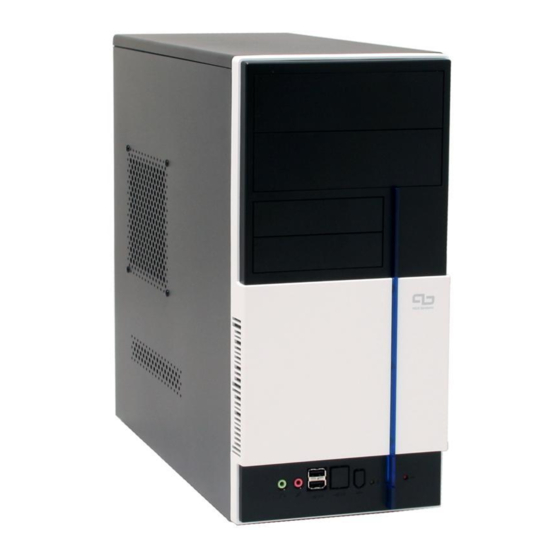
The ASUS Vintage2-AE1 is an all-in-one barebone system with a powerful computing capability, expandability, and versatile connectivity. The system comes in a stylish mini-tower casing and powered by the ASUS motherboard. The system motherboard supports the latest AMD Athlon™ 64/64FX, and Sempron™ desktop processors in the 939-pin package. -
Page 13: Front Panel
Front panel The front panel includes the optical drive bays, floppy disk drive slot, power button, and several I/O ports are located at the front panel. 1 1 1 1 1 2 2 2 2 2 3 3 3 3 3 6 6 6 6 6 4 4 4 4 4 7 7 7 7 7... -
Page 14: Rear Panel
Rear panel The system rear panel includes the power connector and several I/O ports that allow convenient connection of devices. 1 1 1 1 1 2 2 2 2 2 1 1 1 1 1 3 3 3 3 3 1 1 1 1 1 4 4 4 4 4 3 3 3 3 3 4 4 4 4 4... - Page 15 Refer to the audio configuration table below for the function of the audio ports in 2, 4, or 6-channel configuration. A u d i o 2 , 4 , o r 6 - c h a n n e l c o n f i g u r a t i o n A u d i o 2 , 4 , o r 6 - c h a n n e l c o n f i g u r a t i o n A u d i o 2 , 4 , o r 6 - c h a n n e l c o n f i g u r a t i o n A u d i o 2 , 4 , o r 6 - c h a n n e l c o n f i g u r a t i o n...
-
Page 16: Internal Components
5.25-inch optical drive bays Hard disk drive bay Floppy disk drive bay Power supply unit CPU socket DIMM sockets ASUS motherboard Chassis fan 10. AGP slot 11. PCI Express x1 slot 12. PCI slots 13. Metal bracket lock 1 - 6... - Page 17 Chapter 2 This chapter provides step-by-step instructions on how to install components in the system. A S U S V i n t a g e 2 - A E 1 A S U S V i n t a g e 2 - A E 1 A S U S V i n t a g e 2 - A E 1 A S U S V i n t a g e 2 - A E 1 A S U S V i n t a g e 2 - A E 1...
-
Page 18: Chapter 2: Basic Installation
Preparation Before you proceed, make sure that you have all the components you plan to install in the system. Basic components to install: Basic components to install: Basic components to install: Basic components to install: Basic components to install: Central processing unit (CPU) DDR Dual Inline Memory Module (DIMM) Expansion card(s) Hard disk drive... -
Page 19: Removing The Side Cover And Front Panel Assembly
Removing the side cover and front panel assembly Remove the cover screws on the rear panel. Pull the side cover toward the rear panel until its hooks disengage from the chassis. Set the side cover aside. Locate the front panel assembly hooks, then lift them until they disengage from the chassis. -
Page 20: Central Processing Unit (Cpu)
Central Processing Unit (CPU) 2.4.1 2.4.1 Overview Overview 2.4.1 2.4.1 2.4.1 Overview Overview Overview The motherboard comes with a surface mount 939-pin Zero Insertion Force (ZIF) socket designed for the AMD Athlon™ 64/64FX or Sempron™ processor. The 128-bit-wide data paths of these processors can run applications faster than processors with only 32-bit or 64-bit wide data paths. - Page 21 Position the CPU above the socket such that the CPU corner with the gold triangle matches the socket corner with a small triangle. Carefully insert the CPU into the socket until it fits in place. The CPU fits only in one correct orientation.
-
Page 22: Installing The Cpu Fan And Heatsink Assembly
2.4.3 2.4.3 2.4.3 Installing the CPU fan and heatsink assembly Installing the CPU fan and heatsink assembly Installing the CPU fan and heatsink assembly 2.4.3 2.4.3 Installing the CPU fan and heatsink assembly Installing the CPU fan and heatsink assembly The AMD Athlon™... - Page 23 To install the CPU fan and heatsink assembly: Place the heatsink on top of the installed CPU. Make sure that the fan and heatsink assembly perfectly fits the retention mechanism module base; otherwise you can not lock the retention bracket. Attach one end of the retention bracket to the retention module base.
-
Page 24: Installing A Dimm
Installing a DIMM The system motherboard comes with two Double Data Rate (DDR) Dual Inline Memory Module (DIMM) sockets. The following figure illustrates the location of the sockets: ® 184-pin DDR DIMM sockets 2.5.1 2.5.1 Memory configurations Memory configurations 2.5.1 2.5.1 2.5.1 Memory configurations... - Page 25 DDR400 Qualified Vendors List DDR400 Qualified Vendors List DDR400 Qualified Vendors List DDR400 Qualified Vendors List DDR400 Qualified Vendors List S i z e S i z e S i z e S i z e S i z e V e n d o r V e n d o r V e n d o r...
- Page 26 B B B B B - supports one pair of modules inserted into both slots as one pair of Dual-channel memory configuration. Visit the ASUS website (www.asus.com) for the latest Qualified Vendors List. 2 - 1 0 2 - 1 0...
-
Page 27: Removing A Dimm
2.5.2 2.5.2 2.5.2 Installing a DIMM Installing a DIMM Installing a DIMM 2.5.2 2.5.2 Installing a DIMM Installing a DIMM Make sure to unplug the power supply before adding or removing DIMMs or other system components. Failure to do so may cause severe damage to both the motherboard and the components. -
Page 28: Expansion Slots
Expansion slots In the future, you may need to install expansion cards. The following sub-sections describe the slots and the expansion cards that they support. Make sure to unplug the power cord before adding or removing expansion cards. Failure to do so may cause you physical injury and damage motherboard components. -
Page 29: Configuring An Expansion Card
2.6.2 2.6.2 2.6.2 Configuring an expansion card Configuring an expansion card Configuring an expansion card 2.6.2 2.6.2 Configuring an expansion card Configuring an expansion card After installing the expansion card, configure it by adjusting the software settings. Turn on the system and change the necessary BIOS settings, if any. See Chapter 5 for information on BIOS setup. -
Page 30: Pci Slots
2.6.3 2.6.3 2.6.3 PCI slots PCI slots PCI slots 2.6.3 2.6.3 PCI slots PCI slots The PCI slots support cards such as a LAN card, SCSI card, USB card, and other cards that comply with PCI specifications. The figure shows a LAN card installed on a PCI slot. -
Page 31: Wireless Lan Module (Optional)
(optional) (optional) 2.6.6 2.6.6 2.6.6 Wireless LAN module Wireless LAN module Wireless LAN module (optional) (optional) (optional) 2.6.6 2.6.6 Wireless LAN module Wireless LAN module This motherboard supports an optional LAN module that allows you to set up a wireless network and exchange information with other wireless devices without tangling cables and wires. -
Page 32: Installing Storage Drives
Installing storage drives 2.7.1 2.7.1 Optical drive Optical drive 2.7.1 2.7.1 2.7.1 Optical drive Optical drive Optical drive The system supports up to two 5.25” optical drives such as CD-ROM, CD-RW, DVD-ROM, and DVD-RW drives. To install an optical drive: Place the chassis upright, then remove the upper 5.25”... -
Page 33: Floppy Disk Drive
2.7.2 2.7.2 2.7.2 Floppy disk drive Floppy disk drive Floppy disk drive 2.7.2 2.7.2 Floppy disk drive Floppy disk drive The system supports a 3.5” floppy disk drive. To install a floppy disk drive: Place the chassis upright, then remove the lower 3.5” drive bay metal plate cover. -
Page 34: Hard Disk Drive
2.7.3 2.7.3 2.7.3 Hard disk drive Hard disk drive Hard disk drive 2.7.3 2.7.3 Hard disk drive Hard disk drive The system supports a 3.5” IDE or SATA hard disk drive. To install a hard disk drive: Place the chassis upright, then remove the upper 3.5” drive bay metal plate cover. -
Page 35: Connecting Cables
Connecting cables You may have disconnected some cables when you installed system components. Connect these cables before you replace the chassis cover. Front panel buttons and LEDs Front panel buttons and LEDs Front panel buttons and LEDs Front panel buttons and LEDs Front panel buttons and LEDs Connect the r e s e t b u t t o n , p o w e r s w i t c h r e s e t b u t t o n , p o w e r s w i t c h... -
Page 36: Removing The Bay Covers
Removing the bay covers If you installed an optical and/or floppy disk drive, remove the bay cover(s) on the front panel assembly before reinstalling it to the chassis. To do this: Locate the bay cover locks. Press the locks outward to release the bay cover. - Page 37 Chapter 3 This chapter helps you power up the system and install drivers and utilities from the support CD. A S U S V i n t a g e 2 - A E 1 A S U S V i n t a g e 2 - A E 1 A S U S V i n t a g e 2 - A E 1 A S U S V i n t a g e 2 - A E 1 A S U S V i n t a g e 2 - A E 1...
-
Page 38: Chapter 3: Starting Up
The contents of the support CD are subject to change at any time without notice. Visit the ASUS website regularly for updates. Place the CD in the optical drive. The CD automatically displays the... -
Page 39: Drivers Menu
3.3.1 3.3.1 3.3.1 Drivers menu Drivers menu Drivers menu 3.3.1 3.3.1 Drivers menu Drivers menu The drivers menu shows the available device drivers if the system detects installed devices. Install the necessary drivers to activate the devices. AMD Cool ‘n’ Quiet Driver AMD Cool ‘n’... -
Page 40: Utilities Menu
ASUS Update ASUS Update ASUS Update ASUS Update The ASUS Update utility allows you to update the motherboard BIOS in a Windows ® environment. This utility requires an Internet connection either through a network or an Internet Service Provider (ISP). -
Page 41: Make Disk Menu
Microsoft Windows XP Service Pack 2 already includes Microsoft Direct X 9.0c. If your system is Microsoft Windows XP Service Pack 2-embedded, skip Microsoft Direct X 9.0c installation. Anti-virus utility Anti-virus utility Anti-virus utility Anti-virus utility Anti-virus utility The anti-virus utility scans, identifies, and removes computer viruses. View the online help for detailed information. -
Page 42: Manuals Menu
3.3.4 3.3.4 3.3.4 Manuals menu Manuals menu Manuals menu 3.3.4 3.3.4 Manuals menu Manuals menu The Make Disk menu allows you to make a RAID driver disk. RTL8187 Wireless LAN User’s Manual RTL8187 Wireless LAN User’s Manual RTL8187 Wireless LAN User’s Manual RTL8187 Wireless LAN User’s Manual RTL8187 Wireless LAN User’s Manual Allows you to open the Realtek... -
Page 43: Asus Contact Information
C o n t a c t C o n t a c t C o n t a c t tab to display the ASUS contact information. You can also find this information on the inside front cover of this user guide. - Page 44 Displays the support CD contents in graphical format. Technical support Form Technical support Form Technical support Form Technical support Form Technical support Form Displays the ASUS Technical Support Request Form that you have to fill out when requesting technical support. Filelist Filelist Filelist Filelist...
-
Page 45: Software Information
Autorun feature. If Autorun is not enabled in your computer, browse the contents of the support CD to locate the setup.exe file from the ASUS PC Probe II folder. Double-click the setup.exe file to start installation. - Page 46 B u t t o n B u t t o n B u t t o n B u t t o n B u t t o n F u n c t i o n F u n c t i o n F u n c t i o n F u n c t i o n F u n c t i o n...
- Page 47 Hardware monitor panels Hardware monitor panels Hardware monitor panels Hardware monitor panels Hardware monitor panels The hardware monitor panels display the current value of a system sensor such as fan rotation, CPU temperature, and voltages. The hardware monitor panels come in two display modes: hexagonal (large) and rectangular (small).
- Page 48 M o n i t o r i n g s e n s o r a l e r t M o n i t o r i n g s e n s o r a l e r t M o n i t o r i n g s e n s o r a l e r t M o n i t o r i n g s e n s o r a l e r t M o n i t o r i n g s e n s o r a l e r t...
- Page 49 DMI browser DMI browser DMI browser DMI browser DMI browser Click to display the DMI (Desktop Management Interface) browser. This browser displays various desktop and system information. Click the D M I I n f o r m a t i o n D M I I n f o r m a t i o n plus sign (+) before D M I I n f o r m a t i o n D M I I n f o r m a t i o n...
- Page 50 U s a g e U s a g e U s a g e U s a g e U s a g e The U s a g e U s a g e U s a g e U s a g e U s a g e browser displays real-time information on the CPU, hard disk drive space, and memory usage.
- Page 51 H a r d d i s k d r i v e s p a c e u s a g e H a r d d i s k d r i v e s p a c e u s a g e H a r d d i s k d r i v e s p a c e u s a g e H a r d d i s k d r i v e s p a c e u s a g e H a r d d i s k d r i v e s p a c e u s a g e...
-
Page 52: Cool 'N' Quiet!™ Technology
3.4.2 3.4.2 3.4.2 Cool ‘n’ Quiet!™ Technology Cool ‘n’ Quiet!™ Technology Cool ‘n’ Quiet!™ Technology 3.4.2 3.4.2 Cool ‘n’ Quiet!™ Technology Cool ‘n’ Quiet!™ Technology • Make sure to install the Cool ‘n’ Quiet!™ driver and application before using this feature. •... - Page 53 Launching the Cool ‘n’ Quiet!™ application Launching the Cool ‘n’ Quiet!™ application Launching the Cool ‘n’ Quiet!™ application Launching the Cool ‘n’ Quiet!™ application Launching the Cool ‘n’ Quiet!™ application The motherboard support CD includes the Cool ‘n’ Quiet!™ software application that enables you to view your system’s real-time CPU frequency and core voltage.
-
Page 54: Asus Update Utility
ASUS Update utility 3.4.3 3.4.3 ASUS Update utility ASUS Update utility The ASUS Update is a utility that allows you to manage, save, and update the motherboard BIOS in Windows ® environment. The ASUS Update utility allows you to: • Save the current BIOS file •... - Page 55 Updating the BIOS through the Internet Updating the BIOS through the Internet Updating the BIOS through the Internet To update the BIOS through the Internet: Launch the ASUS Update utility from the Windows ® desktop by clicking S t a r t S t a r t >...
- Page 56 A S U S U p d a t e A S U S U p d a t e A S U S U p d a t e. The ASUS Update main window appears. A S U S U p d a t e...
-
Page 57: Asus Mylogo
3.4.4 ASUS MyLogo™ ASUS MyLogo™ The ASUS MyLogo™ utility lets you customize the boot logo. The boot logo is the image that appears on screen during the Power-On Self-Tests (POST). The ASUS MyLogo™ is automatically installed when you install the... - Page 58 R a t i o R a t i o box. When the screen returns to the ASUS Update utility, flash the original BIOS to load the new boot logo. 10. After flashing the BIOS, restart the computer to display the new boot logo during POST.
-
Page 59: Using The Wireless Lan Module
3.4.5 3.4.5 3.4.5 Using the Wireless LAN module Using the Wireless LAN module Using the Wireless LAN module 3.4.5 3.4.5 Using the Wireless LAN module Using the Wireless LAN module • The wireless LAN module is an optional item. • For detailed information on using the Wireless LAN module, view/ download the RTL8187 Wireless LAN User’s Manual on the motherboard support CD. - Page 60 Driver installation Driver installation Driver installation Driver installation Driver installation If you are using a Windows ® operating system, your computer auto-detects the wireless LAN module during start-up and displays an A d d N e w H a r d w a r e W i z a r d A d d N e w H a r d w a r e W i z a r d A d d N e w H a r d w a r e W i z a r d window.
- Page 61 Network setup Network setup Network setup Network setup Network setup You can use the wireless LAN module in various wireless network configurations. After installing the wireless LAN adapter drivers to your computer, select the most appropriate configuration for your home or office wireless network.
- Page 62 Configuration options Configuration options Configuration options Configuration options Configuration options Below are some of the wireless network configurations that you can use for your wireless LAN module. The following descriptions are for reference only and may not exactly match your actual network configuration. Ad-hoc mode When in A d - h o c A d - h o c...
- Page 63 Chapter 4 This chapter gives information about the motherboard that comes with the system. This chapter includes the motherboard layout, jumper settings, and connector locations. A S U S V i n t a g e 2 - A E 1 A S U S V i n t a g e 2 - A E 1 A S U S V i n t a g e 2 - A E 1 A S U S V i n t a g e 2 - A E 1...
-
Page 64: Chapter 4: Motherboard Info
Motherboard information The barebone system comes with an ASUS motherboard. This chapter provides technical information about the motherboard for future upgrades or system reconfiguration. Motherboard layout Motherboard layout Motherboard layout Motherboard layout Motherboard layout 21.8cm (8.6in) PS/2KBMS T: Mouse KBPWR... -
Page 65: Jumpers
Jumpers 1 . 1 . C l e a r R T C R A M ( C L R T C ) C l e a r R T C R A M ( C L R T C ) C l e a r R T C R A M ( C L R T C ) C l e a r R T C R A M ( C L R T C ) C l e a r R T C R A M ( C L R T C ) - Page 66 2 . 2 . K e y b o a r d p o w e r ( 3 - p i n K B P W R ) K e y b o a r d p o w e r ( 3 - p i n K B P W R ) K e y b o a r d p o w e r ( 3 - p i n K B P W R ) K e y b o a r d p o w e r ( 3 - p i n K B P W R ) K e y b o a r d p o w e r ( 3 - p i n K B P W R )
- Page 67 3 . 3 . U S B d e v i c e w a k e - u p ( 3 - p i n U S B P W 1 2 , U S B P W 3 4 , U S B d e v i c e w a k e - u p ( 3 - p i n U S B P W 1 2 , U S B P W 3 4 , U S B d e v i c e w a k e - u p ( 3 - p i n U S B P W 1 2 , U S B P W 3 4 , U S B d e v i c e w a k e - u p ( 3 - p i n U S B P W 1 2 , U S B P W 3 4 ,...
-
Page 68: Connectors
Connectors 4.3.1 4.3.1 Rear panel connectors Rear panel connectors 4.3.1 4.3.1 4.3.1 Rear panel connectors Rear panel connectors Rear panel connectors Refer to section “1.3 Rear panel” for details on the rear panel connectors. 4.3.2 4.3.2 4.3.2 Internal connectors Internal connectors Internal connectors 4.3.2 4.3.2... - Page 69 NOTE: Orient the red markings (usually zigzag) on the IDE ribbon cable to PIN 1. ® PIN 1 PIN 1 IDE connectors 3 . 3 . S e r i a l A T A c o n n e c t o r s ( 7 - p i n S A T A 1 , S A T A 2 ) S e r i a l A T A c o n n e c t o r s ( 7 - p i n S A T A 1 , S A T A 2 ) S e r i a l A T A c o n n e c t o r s ( 7 - p i n S A T A 1 , S A T A 2 ) S e r i a l A T A c o n n e c t o r s ( 7 - p i n S A T A 1 , S A T A 2 )
- Page 70 4 . 4 . 4 . 4 . CPU and chassis fan connectors (3-pin CPU_FAN, CHA_FAN) CPU and chassis fan connectors (3-pin CPU_FAN, CHA_FAN) CPU and chassis fan connectors (3-pin CPU_FAN, CHA_FAN) CPU and chassis fan connectors (3-pin CPU_FAN, CHA_FAN) CPU and chassis fan connectors (3-pin CPU_FAN, CHA_FAN) The fan connectors support cooling fans of 350 mA~740 mA (8.88 W max.) or a total of 1 A~2.22 A (26.64 W max.) at +12V.
- Page 71 6 . 6 . U S B c o n n e c t o r s ( 1 0 - 1 p i n U S B 5 6 , U S B 7 8 ) U S B c o n n e c t o r s ( 1 0 - 1 p i n U S B 5 6 , U S B 7 8 ) U S B c o n n e c t o r s ( 1 0 - 1 p i n U S B 5 6 , U S B 7 8 ) U S B c o n n e c t o r s ( 1 0 - 1 p i n U S B 5 6 , U S B 7 8 ) U S B c o n n e c t o r s ( 1 0 - 1 p i n U S B 5 6 , U S B 7 8 )
- Page 72 8 . 8 . F r o n t p a n e l a u d i o c o n n e c t o r ( 1 0 - 1 p i n F P _ A U D I O ) F r o n t p a n e l a u d i o c o n n e c t o r ( 1 0 - 1 p i n F P _ A U D I O ) F r o n t p a n e l a u d i o c o n n e c t o r ( 1 0 - 1 p i n F P _ A U D I O ) F r o n t p a n e l a u d i o c o n n e c t o r ( 1 0 - 1 p i n F P _ A U D I O )
- Page 73 1 0 . 1 0 . 1 0 . S y s t e m p a n e l c o n n e c t o r ( 2 0 - 1 p i n P A N E L ) S y s t e m p a n e l c o n n e c t o r ( 2 0 - 1 p i n P A N E L ) S y s t e m p a n e l c o n n e c t o r ( 2 0 - 1 p i n P A N E L ) S y s t e m p a n e l c o n n e c t o r ( 2 0 - 1 p i n P A N E L )
- Page 74 4 - 1 2 4 - 1 2 4 - 1 2 4 - 1 2 4 - 1 2 C h a p t e r 4 : M o t h e r b o a r d i n f o C h a p t e r 4 : M o t h e r b o a r d i n f o C h a p t e r 4 : M o t h e r b o a r d i n f o C h a p t e r 4 : M o t h e r b o a r d i n f o...
- Page 75 Chapter 5 This chapter tells how to change system settings through the BIOS Setup menus and describes the BIOS parameters. A S U S V i n t a g e 2 - A E 1 A S U S V i n t a g e 2 - A E 1 A S U S V i n t a g e 2 - A E 1 A S U S V i n t a g e 2 - A E 1 A S U S V i n t a g e 2 - A E 1...
-
Page 76: Chapter 5: Bios Setup
Refer to the corresponding sections for details on these utilities. Save a copy of the original motherboard BIOS file to a bootable floppy disk in case you need to restore the BIOS in the future. Copy the original motherboard BIOS using the ASUS Update or AFUDOS utilities. 5.1.1 5.1.1 5.1.1... -
Page 77: Asus Ez Flash Utility
ASUS EZ Flash utility ASUS EZ Flash utility The ASUS EZ Flash feature allows you to update the BIOS without having to go through the long process of booting from a floppy disk and using a DOS-based utility. The EZ Flash utility is built-in the BIOS chip so it is accessible by pressing <Alt>... -
Page 78: Afudos Utility
5.1.3 5.1.3 5.1.3 AFUDOS utility AFUDOS utility AFUDOS utility 5.1.3 5.1.3 AFUDOS utility AFUDOS utility The AFUDOS utility allows you to update the BIOS file in DOS environment using a bootable floppy disk with the updated BIOS file. This utility also allows you to copy the current BIOS file that you can use as backup when the BIOS fails or gets corrupted during the updating process. - Page 79 Updating the BIOS file To update the BIOS file using the AFUDOS utility: Visit the ASUS website (www.asus.com) and download the latest BIOS file for the motherboard. Save the BIOS file to a bootable floppy disk. Write the BIOS filename on a piece of paper. You need to type the exact BIOS filename at the DOS prompt.
-
Page 80: Asus Crashfree Bios 2 Utility
ASUS CrashFree BIOS 2 utility ASUS CrashFree BIOS 2 utility The ASUS CrashFree BIOS 2 is an auto recovery tool that allows you to restore the BIOS file when it fails or gets corrupted during the updating process. You can update a corrupted BIOS file using the motherboard support CD or the floppy disk that contains the updated BIOS file. - Page 81 Restart the system after the utility completes the updating process. The recovered BIOS may not be the latest BIOS version for this motherboard. Visit the ASUS website (www.asus.com) to download the latest BIOS file. A S U S V i n t a g e 2 - A E 1...
-
Page 82: Bios Setup Program
The BIOS setup screens shown in this section are for reference purposes only, and may not exactly match what you see on your screen. • Visit the ASUS website (www.asus.com) to download the latest BIOS file for this motherboard and . 5 - 8 5 - 8... -
Page 83: Bios Menu Screen
Legacy Diskette A [1.44M, 3.5 in] Use [+] or [-] to Primary IDE Master [ST320410A] configure the System Primary IDE Slave [ASUS CD-S520/A] Time. Secondary IDE Master [Not Detected] Secondary IDE Slave [Not Detected] Third IDE Master [Not Detected]... -
Page 84: Menu Items
[1.44M, 3.5 in.] Primary IDE Master [ST320410A] [+] or [-] to that menu. For example, selecting Primary IDE Slave [ASUS CD-S520/A] configure system time. Secondary IDE Master[Not Detected] Secondary IDE Slave [Not Detected] M a i n M a i n... -
Page 85: Main Menu
Legacy Diskette A [1.44M, 3.5 in] Use [+] or [-] to Primary IDE Master [ST320410A] configure the System Primary IDE Slave [ASUS CD-S520/A] Time. Secondary IDE Master [Not Detected] Secondary IDE Slave [Not Detected] Third IDE Master [Not Detected]... -
Page 86: Primary, Secondary, Third, And Fourth Ide Master/Slave
5.3.4 5.3.4 5.3.4 Primary, Secondary, Third, and Fourth IDE Primary, Secondary, Third, and Fourth IDE Primary, Secondary, Third, and Fourth IDE 5.3.4 5.3.4 Primary, Secondary, Third, and Fourth IDE Primary, Secondary, Third, and Fourth IDE Master/Slave Master/Slave Master/Slave Master/Slave Master/Slave While entering Setup, the BIOS automatically detects the presence of IDE devices. -
Page 87: System Information
PIO Mode [Auto] PIO Mode [Auto] PIO Mode [Auto] PIO Mode [Auto] PIO Mode [Auto] Selects the PIO mode. Configuration options: [Auto] [0] [1] [2] [3] [4] DMA Mode [Auto] DMA Mode [Auto] DMA Mode [Auto] DMA Mode [Auto] DMA Mode [Auto] Selects the DMA mode. -
Page 88: Advanced Menu
Advanced menu The Advanced menu items allow you to change the settings for the CPU and other system devices. Take caution when changing the settings of the Advanced menu items. Incorrect field values can cause the system to malfunction. BIOS SETUP UTILITY Main Advanced Power... -
Page 89: Usb Configuration
5.4.2 5.4.2 5.4.2 USB Configuration USB Configuration USB Configuration 5.4.2 5.4.2 USB Configuration USB Configuration BIOS SETUP UTILITY Advanced Enables 1.1 USB host USB Configuration controllers. Module Version - 2.24.0-10.4 USB Devices Enabled: None USB 1.1 Ports Configuration [USB 8 Ports] USB 2.0 Ports Enable [Enable] Legacy USB Support... -
Page 90: Cpu Configuration
USB 2.0 Controller Mode [HiSpeed] USB 2.0 Controller Mode [HiSpeed] USB 2.0 Controller Mode [HiSpeed] USB 2.0 Controller Mode [HiSpeed] USB 2.0 Controller Mode [HiSpeed] Allows you to set the USB 2.0 controller mode to HiSpeed (480 Mbps) or FullSpeed (12 Mbps). Configuration options: [FullSpeed] [HiSpeed] BIOS EHCI Hand-Off [Enabled] BIOS EHCI Hand-Off [Enabled] BIOS EHCI Hand-Off [Enabled]... -
Page 91: Chipset
5.4.4 5.4.4 5.4.4 Chipset Chipset Chipset 5.4.4 5.4.4 Chipset Chipset The Chipset menu allows you to change the advanced chipset settings. Select an item then press <Enter> to display the sub-menu. BIOS SETUP UTILITY Advanced Options for NB Advanced Chipset Settings WARNING: Setting wrong values in below sections may cause system to malfunction. - Page 92 Memory Configuration BIOS SETUP UTILITY Advanced Memory Configuration MEMCLK can be set by the code using AUTO, Memclock Mode [Auto] or if you use LIMIT, MCT Timing Mode [Auto] you can set one of the User Config Mode [Auto] standard values. Burst Length [4 Beats] Select Screen...
- Page 93 T R R D [ 2 T ] T R R D [ 2 T ] T R R D [ 2 T ] T R R D [ 2 T ] T R R D [ 2 T ] Configuration options: [2T] [3T] [4T] T R C [ 1 2 T ] T R C [ 1 2 T ]...
- Page 94 D R A M S C R U B R E D I R E C T [ D i s a b l e d ] D R A M S C R U B R E D I R E C T [ D i s a b l e d ] D R A M S C R U B R E D I R E C T [ D i s a b l e d ] D R A M S C R U B R E D I R E C T [ D i s a b l e d ] D R A M S C R U B R E D I R E C T [ D i s a b l e d ]...
- Page 95 AGP Bridge VIA K8M800 Configuration AGP Bridge VIA K8M800 Configuration AGP Bridge VIA K8M800 Configuration AGP Bridge VIA K8M800 Configuration AGP Bridge VIA K8M800 Configuration VIA K8M800 Chipset Configuration Advanced OnChip VGA Frame Buffer Size [64MB] Options Primary Graphics Adapter [AGP] VLink 8X Supported [Enabled]...
- Page 96 SouthBridge VIA VT8251 Configuration SouthBridge VIA VT8251 Configuration SouthBridge VIA VT8251 Configuration SouthBridge VIA VT8251 Configuration SouthBridge VIA VT8251 Configuration VIA VT8251 South Chipset Configuration Advanced Options * Serial ATA IDE Controller [SATA] * LAN Controller [Enabled] Disabled LAN BIOS Execute [Disabled] SATA OnChip AC`97 Audio...
- Page 97 HyperTransport Configuration HyperTransport Configuration HyperTransport Configuration HyperTransport Configuration HyperTransport Configuration BIOS Setup Utility Advanced LDT to AGP Lokar Frequency [800 MHz] LDT to AGP Lokar LDT to AGP Lokar (Upstream) [16 BIT] frequency selection. LDT to AGP Width (Downstream) [16 BIT] Select Screen Select Item Change Option...
-
Page 98: Onboard Devices Configuration
5.4.5 5.4.5 5.4.5 Onboard Devices Configuration Onboard Devices Configuration Onboard Devices Configuration 5.4.5 5.4.5 Onboard Devices Configuration Onboard Devices Configuration BIOS SETUP UTILITY Advanced Allows BIOS to select Configure Win627EHF Super IO Chipset Serial Port1 Base Addresses. Serial Port1 Address [3F8/IRQ4] Parallel Port Address [378]... -
Page 99: Pci Pnp
5.4.6 5.4.6 PCI PnP PCI PnP 5.4.6 5.4.6 5.4.6 PCI PnP PCI PnP PCI PnP The PCI PnP menu items allow you to change the advanced settings for PCI/PnP devices. The menu includes setting IRQ and DMA channel resources for either PCI/PnP or legacy ISA devices, and setting the memory size block for legacy ISA devices. -
Page 100: Power Menu
Power menu The Power menu items allow you to change the settings for the Advanced Power Management (APM). Select an item then press <Enter> to display the configuration options. BIOS SETUP UTILITY Main Advanced Power Boot Exit Suspend Mode [Auto] Select the ACPI state Repost Video on S3 Resume [No]... -
Page 101: Apm Configuration
5.5.5 5.5.5 5.5.5 APM Configuration APM Configuration APM Configuration 5.5.5 5.5.5 APM Configuration APM Configuration BIOS SETUP UTILITY Power Options Power Management/APM [Enabled] Disabled Restore on AC Power Loss [Power Off] Enabled Resume On Ring [Disabled] Resume On LAN [Disabled] Resume On PME# [Disabled] Resume On KBC... - Page 102 Resume On KBC [Disabled] Resume On KBC [Disabled] Resume On KBC [Disabled] Resume On KBC [Disabled] Resume On KBC [Disabled] Configuration options: [Disabled] [Enabled] Wake-Up Key [Any Key] Wake-Up Key [Any Key] Wake-Up Key [Any Key] Wake-Up Key [Any Key] Wake-Up Key [Any Key] Allows you to use any key or a specific key on the keyboard to turn on the system.
-
Page 103: Hardware Monitor
CPU Q-Fan Control [Enabled] CPU Q-Fan Control [Enabled] CPU Q-Fan Control [Enabled] Allows you to enable or disable the ASUS Q-Fan feature that smartly adjusts the fan speeds for more efficient system operation. Configuration options: [Disabled] [Enabled] Chassis Fan Speed [xxxxRPM] or [Ignored]... -
Page 104: Boot Menu
VCORE Voltage, 3.3V Voltage, 5V Voltage, 12V Voltage VCORE Voltage, 3.3V Voltage, 5V Voltage, 12V Voltage VCORE Voltage, 3.3V Voltage, 5V Voltage, 12V Voltage VCORE Voltage, 3.3V Voltage, 5V Voltage, 12V Voltage VCORE Voltage, 3.3V Voltage, 5V Voltage, 12V Voltage The onboard hardware monitor automatically detects the voltage output through the onboard voltage regulators. -
Page 105: Boot Device Priority
Specifies the boot sequence from the 1st Boot Device [1st FLOPPY DRIVE] availabe devices. 2nd Boot Device [PM-ST320410A] 3rd Boot Device [PS-ASUS CD-S520/A] A device enclosed in parenthesis has been disabled in the corresponding menu. Select Screen Select Item Change Option... - Page 106 Allows you to enable or disable the full screen logo display feature. Configuration options: [Disabled] [Enabled] Set this item to [Enabled] to use the ASUS MyLogo™ feature. Add On ROM Display Mode [Force BIOS] Add On ROM Display Mode [Force BIOS]...
-
Page 107: Security
5.6.3 5.6.3 5.6.3 Security Security Security 5.6.3 5.6.3 Security Security The Security menu items allow you to change the system security settings. Select an item then press <Enter> to display the configuration options. BIOS SETUP UTILITY Boot Security Settings <Enter> to change password. - Page 108 BIOS SETUP UTILITY Boot Security Settings <Enter> to change password. Supervisor Password : Not Installed <Enter> again to User Password : Not Installed disabled password. Change Supervisor Password User Access Level [Full Access] Change User Password Clear User Password Password Check [Setup] Select Screen Select Item...
-
Page 109: Exit Menu
Clear User Password Clear User Password Clear User Password Clear User Password Clear User Password Select this item to clear the user password. Configuration options: [Setup] [Always] Password Check [Setup] Password Check [Setup] Password Check [Setup] Password Check [Setup] Password Check [Setup] When set to [Setup], BIOS checks for user password when accessing the Setup utility. - Page 110 Exit & Discard Changes Exit & Discard Changes Exit & Discard Changes Exit & Discard Changes Exit & Discard Changes Select this option only if you do not want to save the changes that you made to the Setup program. If you made changes to fields other than System Date, System Time, and Password, the BIOS asks for a confirmation before exiting.