Table of Contents
Advertisement
BEFORE SERVICING ......................................................................................................INSIDE FRONT COVER
WARNING TO SERVICE PERSONNEL ................................................................................................................ 1
MICROWAVE MEASUREMENT PROCEDURE ................................................................................................... 2
FOREWORD AND WARNING ............................................................................................................................... 3
PRODUCT SPECIFICATIONS .............................................................................................................................. 4
GENERAL INFORMATION ................................................................................................................................... 4
OPERATION .......................................................................................................................................................... 6
TROUBLESHOOTING GUIDE ............................................................................................................................ 11
TEST PROCEDURE ............................................................................................................................................ 12
TOUCH CONTROL PANEL ASSEMBLY ............................................................................................................ 21
COMPONENT REPLACEMENT AND ADJUSTMENT PROCEDURE ................................................................ 26
PICTORIAL DIAGRAM ........................................................................................................................................ 34
CONTROL PANEL CIRCUIT ............................................................................................................................... 35
PRINTED WIRING BOARD ................................................................................................................................. 36
PARTS LIST ........................................................................................................................................................ 37
PACKING AND ACCESSORIES ......................................................................................................................... 42
SERVICE MANUAL
MODELS
1 Coffee/tea
CUSTOM HELP
2 Roll/muffin, fresh
BREAKFAST
3 Roll/muffin, frozen
4 Hot cereal
5 Scrambled eggs
1 Dinner plate
POPCORN
SNACKS &
2 Pasta/casserole
REHEAT
3 Frozen entree
4 Frozen snack
5 Pizza, slice
1 Baked potatoes
COMPU DEFROST
COMPU COOK
2 Fresh vegetables
3 Frozen vegetables
4 Rice
5 Ground meat
POWER
KITCHEN TIMER
LEVEL
MINUTE
CLOCK
PLUS
TURNTABLE
In the interest of user-safety the oven should be restored to its original
ON/OFF
STOP
CLEAR
START
TOUCH ON
condition and only parts identical to those specified should be used.
WARNING TO SERVICE PERSONNEL: Microwave ovens con-
tain circuitry capable of producing very high voltage and
current, contact with following parts may result in a severe,
possibly fatal, electrical shock. (High Voltage Capacitor, High
Voltage Power Transformer, Magnetron, High Voltage Recti-
fier Assembly, High Voltage Harness etc..)
TABLE OF CONTENTS
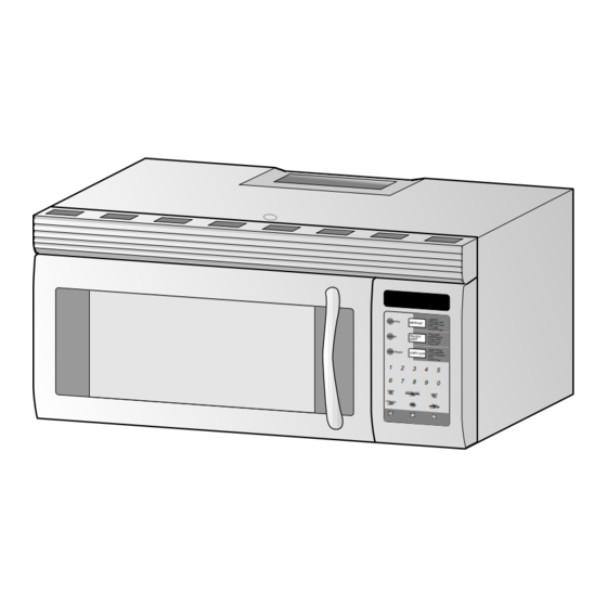
OVER THE RANGE
MICROWAVE OVEN
R-1480
R-1481
R-1482
This document has been published to be used for after
sales service only.
The contents are subject to change without notice.
R-1480
R-1481
R-1482
S3807R1480X//
Page
Advertisement
Table of Contents

Related Manuals for Sharp R-1482


Summary of Contents for Sharp R-1482
-
Page 1: Table Of Contents
R-1480 R-1481 R-1482 SERVICE MANUAL S3807R1480X// OVER THE RANGE MICROWAVE OVEN R-1480 MODELS R-1481 R-1482 1 Coffee/tea CUSTOM HELP 2 Roll/muffin, fresh BREAKFAST 3 Roll/muffin, frozen 4 Hot cereal 5 Scrambled eggs 1 Dinner plate POPCORN SNACKS & 2 Pasta/casserole... -
Page 2: Precautions To Be Observed Before And During Servicing To Avoid Possible Exposure To Excessive Microwave Energy
Before servicing an operative unit, perform a microwave emission check as per the Microwave Measurement Procedure outlined in this service manual. If microwave emissions level is in excess of the specified limit, contact SHARP ELECTRONICS CORPORATION immediately @1-800-237-4277. If the unit operates with the door open, service person should 1) tell the user not to operate the oven and 2) contact SHARP ELECTRONICS CORPORATION and Food and Drug Administration's Center for Devices and Radiological Health immediately. -
Page 3: Warning To Service Personnel
R-1480 R-1481 R-1482 WARNING TO SERVICE PERSONNEL Microwave ovens contain circuitry capable of pro- ducing very high voltage and current, contact with following parts may result in a severe, possibly fatal, electrical shock. (Example) High Voltage Capacitor, High Voltage Power Trans- former, Magnetron, High Voltage Rectifier Assem- bly, High Voltage Harness etc.. -
Page 4: Microwave Measurement Procedure
R-1480 R-1481 R-1482 MICROWAVE MEASUREMENT PROCEDURE A. Requirements: 1) Microwave leakage limit (Power density limit): The power density of microwave radiation emitted by a microwave oven should not exceed 1mW/cm at any point 5cm or more from the external surface of the oven, measured prior to acquisition... -
Page 5: Foreword And Warning
OVER THE RANGE MICROWAVE OVEN R-1480 / R-1481 / R-1482 GENERAL INFORMATION FOREWORD This Manual has been prepared to provide Sharp Electronics Corp. OPERATION Service Personnel with Operation and Service Information for the SHARP OVER THE RANGE MICROWAVE OVEN, R-1480, R-1481, R-1482. -
Page 6: Product Specifications
R-1480 R-1481 R-1482 PRODUCT SPECIFICATION ITEM DESCRIPTION Power Requirements 120 Volts / 14.3 Amperes 60 Hertz Single phase, 3 wire grounded Power Output 950 watts (IEC-705 TEST PROCEDURE) Operating frequency of 2450MHz Convection Power Output 1700 watts Case Dimensions Width 29-15/16"... -
Page 7: Oven Diagram
R-1480 R-1481 R-1482 Electrical Requirements The oven is equipped with a 3-prong grounding plug. DO NOT UNDER ANY CIRCUMSTANCES CUT OR REMOVE THE GROUNDING PIN FROM THE PLUG. The power supply cord and plug must be connected to a separate 120 Volt AC, 60 Hz, 15 Amp. or more branch circuit, using a grounded receptacle. -
Page 8: Operation
R-1480 R-1481 R-1482 CONTROL PANEL MIX CONV COOK LBS KG TURNTABLE OFF HELP 1 Coffee/tea 2 Roll/muffin, fresh BREAKFAST CUSTOM HELP 3 Roll/muffin, frozen 4 Hot cereal 5 Scrambled eggs 1 Dinner plate SNACKS & 2 Pasta/casserole POPCORN 3 Frozen entree... - Page 9 R-1480 R-1481 R-1482 RELAY CONNECTED COMPONENTS VARI-MODE ON TIME OFF TIME Oven lamp / Fan motor / Stirrer motor Power 10(P-HI) 32 sec. 0 sec. (100% power) Power transformer Power 9(P-90) 30 sec. 2 sec. Turntable motor (approx. 90% power)
- Page 10 R-1480 R-1481 R-1482 VENTILATION METHODS HOT AIR EXHAUST 1. VERTICAL VENTING For this venting method, hot air rising from the conventional range below is drawn in by the hood fan motor through the grease filters at the right and left sides...
- Page 11 R-1480 R-1481 R-1482 SCHEMATIC NOTE: CONDITION OF OVEN 1. DOOR CLOSED CLOCK APPEARS ON DISPLAY CAVITY MAGNETRON THERMAL CUT-OUT TEMPERATURE FUSE CONTROL UNIT COM. N.O. FUSE POWER TRANSFORMER HOOD FAN THERMAL High CUT OUT N.C. DOOR SENSING SWITCH HOOD 120 V AC.
- Page 12 R-1480 R-1481 R-1482 DESCRIPTION AND FUNCTION OF COMPONENTS DOOR OPEN MECHANISM CAUTION: BEFORE REPLACING A BLOWN MONITOR FUSE TEST THE DOOR SENSING SWITCH, The door is opened by pulling the door handle, refer to the PRIMARY INTERLOCK RELAY (RY2), SEC- Figure D-1.
-
Page 13: Troubleshooting Guide
R-1480 R-1481 R-1482 HOOD LAMP This air is then expelled either vertically or horizontally through the customer supplied duct system, or discharged The hood lamps are mounted at the hood lamp angle on the back into the kitchen. base cover. The hood lamps can be turned off and on by touching the WORK LIGHT pad or the NIGHT LIGHT pad. - Page 14 R-1480 R-1481 R-1482 CK = Check / RE = Replace CK LOW VOLTAGE CK NO POWER AT OUTLET RE SHORTED IN POWER CORD CK OPENED OR SHORTED WIRING CK HOOD MOTOR CAPACITOR RE HOOD LAMP OR SOCKET CK TURNTABLE OFF CONDITION...
-
Page 15: Test Procedure
R-1480 R-1481 R-1482 TEST PROCEDURES PROCEDURE COMPONENT TEST LETTER MAGNETRON ASSEMBLY TEST 1. Disconnect the power supply cord, and then remove outer case. 2. Open the door and block it open. 3. Discharge high voltage capacitor. 4. To test for an open filament, isolate the magnetron from the high voltage circuit. A continuity check across the magnetron filament leads should indicate less than 1 ohm. - Page 16 R-1480 R-1481 R-1482 TEST PROCEDURES PROCEDURE COMPONENT TEST LETTER (HIGH VOLTAGES ARE PRESENT AT THE HIGH VOLTAGE TERMINAL, SO DO NOT ATTEMPT TO MEASURE THE FILAMENT AND HIGH VOLTAGE.) HIGH VOLTAGE RECTIFIER TEST 1. Disconnect the power supply cord, and then remove outer case.
- Page 17 R-1480 R-1481 R-1482 TEST PROCEDURES PROCEDURE COMPONENT TEST LETTER 6. Reinstall the outer case (cabinet). 7. Reconnect the power supply cord after the outer case is installed. 8. Run the oven and check all functions. CAUTION: IF THE THERMAL CUT-OUT OR TEMPERATURE FUSE INDICATES AN OPEN CIRCUIT AT ROOM TEMPERATURE, REPLACE THERMAL CUT-OUT OR TEMPERATURE FUSE.
- Page 18 R-1480 R-1481 R-1482 TEST PROCEDURES PROCEDURE COMPONENT TEST LETTER with the door opened (in this condition the plunger of the monitor switch is pushed in), the meter should indicate an open circuit. If improper operation is indicated, the switch may be defective. After testing the monitor switch, reconnect the wire lead to the monitor switch (COM) terminal and check the continuity of the monitor circuit.
- Page 19 R-1480 R-1481 R-1482 TEST PROCEDURES PROCEDURE COMPONENT TEST LETTER Resistance between; BLU (1) AND YLW (4) = (Shorted) BLK (2) AND YLW (4) = 32 HOOD FAN BLU (1) AND BLK (2) = 32 CAPACITOR BLK (2) AND WHT (3) = 20...
- Page 20 R-1480 R-1481 R-1482 TEST PROCEDURES PROCEDURE COMPONENT TEST LETTER 7) Reconnect the power supply cord after the outer case is installed. 8) Run the oven and check all functions. 2. Control Unit. The following symptoms indicate a defective control unit. Before replacing the control unit, perform the Key unit test (Procedure M) to determine if control unit is faulty.
- Page 21 R-1480 R-1481 R-1482 TEST PROCEDURES PROCEDURE COMPONENT TEST LETTER RELAY TEST 1. Disconnect the power supply cord, and then remove outer case. 2. Open the door and block it open. 3. Discharge high voltage capacitor. 4. Disconnect the leads to the primary of the power transformer.
- Page 22 R-1480 R-1481 R-1482 TEST PROCEDURES PROCEDURE COMPONENT TEST LETTER STEPS OCCURRENCE CAUSE OR CORRECTION Only pattern at "a" is broken. *Insert jumper wire J1 and solder. Pattern at "a" and "b" are broken. *Insert the coil RCILF2003YAZZ between "c" and "d".
-
Page 23: Touch Control Panel Assembly
R-1480 R-1481 R-1482 TOUCH CONTROL PANEL ASSEMBLY OUTLINE OF TOUCH CONTROL PANEL The touch control section consists of the following units 3) Synchronizing Signal Circuit The power source synchronizing signal is available in as shown in the touch control panel circuit. -
Page 24: Description Of Lsi
R-1480 R-1481 R-1482 DESCRIPTION OF LSI LSI(IZA876DR) The I/O signals of the LSI(IZA876DR) are detailed in the following table. Pin No. Signal Description Connected to GND. Anode (segment) of Fluorescent Display illumination voltage: -31V. Vp voltage of power source circuit input. - Page 25 R-1480 R-1481 R-1482 Pin No. Signal Description Terminal not used. Signal to sound buzzer. 0.1 sec A: key touch sound. 2 sec B: Completion sound. C: When the temperature of the oven cavity reaches the preset temperature in the preheating mode,...
- Page 26 R-1480 R-1481 R-1482 Pin No. Signal Description 41-44 P17-P14 Digit selection signal. Signal similar to P23. 45-48 P13-P10 Segment data signals. The relation between signals and indicators are as follows: Signal Segment Signal Segment P13 ....P15 P03 ....P7 P12 ....
- Page 27 R-1480 R-1481 R-1482 SERVICING 1. Precautions for Handling Electronic Components 5) Re-connect the power supply cord after the outer case is This unit uses CMOS LSI in the integral part of the installed. circuits. When handling these parts, the following 6) Run the oven and check all functions.
-
Page 28: Component Replacement And Adjustment Procedure
3. The door gasket or seal is damaged. 4. If the outer case (cabinet) is not fitted. WARNING FOR WIRING To prevent an electric shock, take the following pre- 3) Sharp edge: cautions. Bottom plate, Oven cavity, Waveguide flange, 1. Before wiring, Chassis support and other metallic plate. - Page 29 R-1480 R-1481 R-1482 4. Pull the hood exhaust louver from the oven cavity by to remove. pushing the right and left tabs of the hood exhaust louver 5. Now, the hood exhaust louver is free. REMOVAL OF OVEN FROM WALL (Two persons recommended to remove the oven) 1.
- Page 30 R-1480 R-1481 R-1482 hood duct. 17.Now, the oven lamp socket and the hood duct are free. 10.Remove the two (2) unit mounting screws from the Oven lamp chassis support (right side) and the hood duct (left side). socket 11.Remove the one (1) screw holding the chassis support.
-
Page 31: Cooling Fan Motor Removal
R-1480 R-1481 R-1482 NOTE: When the tab is broken or turned off, use the another 3. Discharge high voltage capacitor. tab which is fixed near the slit when the new thermal 4. Remove two (2) unit mounting screws. cut-out is replaced. - Page 32 R-1480 R-1481 R-1482 6. Install the hood duct to the oven cavity with the one (1) Shaft screw. 7. Re-install the wire leads to the hole of the hood duct. 8. Connect the wire leads to the fan motor and chassis support, referring to the pictorial diagram.
- Page 33 R-1480 R-1481 R-1482 the control panel. of the display board as shown in step 3. 17.Remove the key fixing plate from the control panel. 4. Insert the bottom edge of the display board under the tab 18.Tear the key unit from the key fixing plate.
- Page 34 R-1480 R-1481 R-1482 switch is in the lower position, door sensing switch is in procedure of "CONTROL PANEL ASSEMBLY , the upper position and the monitor switch is in the middle CONTROL UNIT AND KEY UNIT REMOVAL". position. 5. Remove the two (2) screws holding the latch hook to the 2.
-
Page 35: Door Disassembly
R-1480 R-1481 R-1482 latch holes correctly. of microwave energy from oven cavity during 6. Re-install the door stopper to the door assembly. cook cycle. This function does not require that 7. Re-install the hood exhaust louver to the oven cavity door be air-tight, moisture (condensation)-tight front face plate. -
Page 36: Pictorial Diagram
R-1480 R-1481 R-1482... -
Page 37: Control Panel Circuit
R-1480 R-1481 R-1482 3.3k 3.3k 3.3k D752 3.3k 3.3k 3.3k 3.3k 100k 100k 100k 3.3k 3.3k 3.3k 3.3k IZA876DR (J15) 4.7k (J7) 4.7k (J5) HZ4A2 (J3) (J6) /35v (J4) /50v (J2) HZ5C2 3.3k /50v SP40 /35v HZ6A3 1/2w 4.3k /35v... -
Page 38: Printed Wiring Board
R-1480 R-1481 R-1482 ,BFB (J10) (IC2) (J11) (J12) (D70) (R76) (R100) (J15) SP40 SSR1 (Q1) C110 (R2) R110 (ZD2) (470V) VRS1 (CN - A) CN - A MICRO AC(N) TTM AC(H) Figure S-3. Printed Wiring Board... -
Page 39: Parts List
2- 7 FANGKB009MRY0 Hood lamp glass assembly [R-1480] 2- 7 FANGKB010MRY0 Hood lamp glass assembly [R-1481] 2- 7 FANGKB011MRY0 Hood lamp glass assembly [R-1482] 2-7-1 LANGQB016MRP0 Hood lamp glass angle [R-1480] 2-7-1 LANGQB020MRP0 Hood lamp glass angle [R-1481] 2-7-1 LANGQB027MRP0... - Page 40 Zener diode (HZ4A-2) 3- 2 FPNLCB205MRK0 Control panel sub. assembly [R-1480] 3- 2 FPNLCB211MRK0 Control panel sub, assembly [R-1481] 3- 2 FPNLCB212MRK0 Control panel sub, assembly [R-1482] 3- 2-1 FUNTKB153MRE0 Key unit [R-1480] 3- 2-1 FUNTKB159MRE0 Key unit [R-1481] 3- 2-1 FUNTKB160MRE0...
- Page 41 To have your order filled promptly and correctly, please furnish the following information. 1. MODEL NUMBER 2. REF. NO. 3. PART NO. 4. DESCRIPTION Order Parts from the authorized SHARP parts Distributor for your area. Defective parts requiring return should be returned as indicated in the Service Policy.
- Page 42 R-1480 R-1481 R-1482 OVEN AND CABINET PARTS 1-14 4-13 4-19 4-10 4-12 4-11 1-12 1-15 1-16 1-13 1-17 4-18 6-10 4-18 6-12 4-16 4-20 1-10 4-22 1-11 4-14 4-17 1-10 6-14 6-13 4-15 1-13 6-13 2-7-2 1-16 2-7-1...
- Page 43 R-1480 R-1481 R-1482 CONTROL PANEL PARTS 3 - 3 3 - 2 3-1E 3-2-2 3 - 1 3-2-1 3 - 3 7 - 3 DOOR PARTS 3 - 3 4-21 5-2-1 5-2-3 5-2-2 MISCELLANEOUS 5-2-4 6-1-1 6-1-4 6-1-5 6-1-2 6-1-6...
-
Page 44: Packing And Accessories
No part of this publication may be repro- duced, stored in retrieval systems, or trans- mitted in any form or by any means, elec- tronic, mechanical, photocopying, record- ing, or otherwise, without prior written per- mission of the publisher. '98 SHARP CORP. (3S2.530E) Printed in U.S.A...