Table of Contents
Advertisement
Advertisement
Table of Contents
Troubleshooting

Related Manuals for LG G3L-PUEA


Summary of Contents for LG G3L-PUEA
- Page 1 USER’S MANUAL LG Programmable Logic Controller Profibus-DP Module G3L-PUEA GLOFA G3L-PUEB G4L-PUEA MASTER-K G4L-PUEB G6L-PUEA G6L-PUEB G7L-PBEA Before using, please read ‘ Notices for the safety ’thoroughly. Please keep this user’s manual in the place where the user can find easily.
- Page 2 Notices for the Safety ‘Notices for the Safety’ should be complied by the user to use the product safely and correctly to prevent the occurrence of any accident or danger. ‘Notices for the Safety’ is divided by “Danger”, ”Warning” and ”Caution” and each meaning is as follows : In case of violating the instructions, it may cause the Danger...
-
Page 3: Notices In Installation
Notices in Design ■ Caution I/O Signal/Communication cables shall be designed apart at least 100mm from high voltage cable or power cable to avoid the influence caused by the noise or the change of magnetic filed. It may cause the malfunction by the noise. In case that installation environment has lots of vibration, cares should be taken not to apply the vibration to the product directly. - Page 4 ■ Notices in Startup and Maintenance Warning Do not touch the terminal in the state that the power is applied. It may cause the malfunction or electric shock. Caution Do not remove PCB from the module case or remodel the module. It may cause the failure, malfunction, damage of the product or fire.
- Page 5 REVISION HISTORY Issue Date Manual No. Revised Content ’04.4 10310000334 First edition issued. ※User’s Manual no. is marked on the right bottom side of the back cover.
-
Page 6: Table Of Contents
Table of Contents CHAPTER 1 OVERVIEW 1-1 ~ 1-2 1.1 Notices in using CHAPTER 2 TERMINOLOGY 2-1 ~ 2-2 CHAPTER 3 GENERAL SPECIFICATION 3-1 ~ 3-2 3.1 General Specification 3.2 Pnet Telecommunication module structure CHAPTER 4 PERFORMANCE SPECIFICATION 4.1 Telecommunication Specification CHAPTER 5 SYSTEM CONFIGURATION 5.1 Profibus-DP System CHAPTER 6 TELECOMMUNICATION CONFIGURATION... - Page 7 CHAPTER 7 DIAGNOSIS FUNCTION 7-1 ~ 7-2 7.1 LED CHAPTER 8 INSTALLATION & STARTUP 8-1 ~ 8-7 8.1 Installation 8.1.1 Notices in installation 8.1.2 Cable installation 8.2 Startup 8.2.1 Notices in system configuration 8.2.2 Checklist before startup 8.3 Maintenance & Checking 8.3.1 Daily checking 8.3.2 Regular checking CHAPTER 9 TROUBLE SHOOTING...
- Page 8 CHAPTER 1 OVERVIEW CHAPTER 1 OVERVIEW This user’s manual describes GLOFA-GM/MASTER-K Profibus (hereinafter referred as‘Pnet’) which is Profibus module among network modules of PLC system technically in detail. Please refer to the following user’s manuals to prepare the program. GLOFA-GM PLC Command collection GLOFA-GM PLC GMWIN User’s manual MASTER-K PLC Command collection MASTER-K PLC KGLWIN User’s manual...
-
Page 9: Chapter 1 Overview 1-1
CHAPTER 1 OVERVIEW 1.1 Notices in using When you install this device, cares should be taken to the following items for the reliability and safety of system. Items Classification Description • When installing this device, the use temperature should be 0 ~ Temperature Condition 55℃... -
Page 10: Chapter 2 Terminology 2-1
CHAPTER 2 TERMINOLOGY CHAPTER 2 TERMINOLOGY Profibus Profibus is a protocol designated as German standard DIN 19245, developed by Bosch, Siemens, Klockener-Moeller in Germany and also a network designated as European standard EN50170 together with WorldFIP, P-NET. Profibus is used for the real time communication between field equipments in the area of production automation, processing control, building automation etc. - Page 11 CHAPTER 2 TERMINOLOGY Broadcast Communication This is to send the message not recognized by Operation Station to all station (Master, Slave). Multicast Communication This is to send the not recognized message to the pre-fixed Station group (Master, Slave) by Operation Station.
-
Page 12: Chapter 3 General Specification 3-1
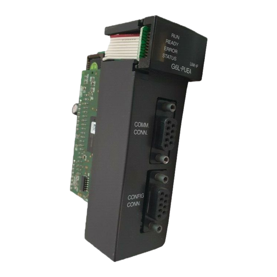
CHAPTER 3 GENERAL SPECIFICATION CHAPTER 3 GENERAL SPECIFICATION 3.1 General Specification The General Specification for the communication module of GLOFA series and MASTER-K series is as follows: Items Specification Reference 0 ~ 55 °C Use Temperature −25°C ~ +70 °C Storage Temp. - Page 13 CHAPTER 3 GENERAL SPECIFICATION 3.2 Pnet I/F Module Configuration G3L-PUEA G4L-PUEA G6L-PUEA READY READY READY ERROR ERROR ERROR STATUS LINK STATUS STATUS LINK-IF LINK-IF G7L-PBEA COM RUN COMM. PROGRAMMABLE LOGIC ERROR LINK-IF CONN. CONTROLLER CONFIG. COMM. CONN. CONN. CONFIG. CONN.
-
Page 14: Chapter 4 Performance Specification
CHAPTER 4 PERFORMANCE SPECIFICATION CHAPTER 4 PERFORMANCE SPECIFICATION 4.1 Communication Specification Type G3/4/6L-PUEA G3/4/6L-PUEB G7L-PBEA Items Module type Master Slave Network type Profibus-DP Standard EN50170/DIN19245 Interface RS-485(electric power) Transmission mode Bus mode Modulation mode Local token ring Poll 1000m(9.6k~187kbps) Total extension length & 400m(500kbps) speed 200m(1.5Mbps) -
Page 15: Chapter 5 System Configuration
CHAPTER 5 SYSTEM CONFIGURATION CHAPTER 5 SYSTEM CONFIGURATION 5.1 Profibus-DP System Sycon GMWIN Configuration software GM4/K300S G6L-PUEA/PUEB GM3/K1000S G4L-PUEA/PUEB G3L-PUEA/PUEB SmartI/O SmartI/O GPL-D22A/C GPL-RY2A/C GM7/K80S,K120S GPL-TR2A/A1/C1 GPL-D24A/C GPL-TR2B/C GPL-DT4A/A1/B/C/C1 G7L-PBEA GPL-TR4A/A1/B/C/C1 LG PLC SIEMENS PLC SmartI/O GM7/K80S,K120S G7L-PBEA... -
Page 16: High Speed Link
CHAPTER 6 COMMUNICATION FUNCTION CHAPTER 6 COMMUNICATION FUNCTION Supports only the high speed link communication. Parameter setting and configuration in SyCon and GMWIN/KGLWIN. Sets only sending/receiving area in GMWIN high speed link parameter setting. The sending/receiving data shall be saved and sent continuously from the setting area. (e.g. similar to the continued MAP of MASTER-K.) The number of sending/receiving and slave area per slave station shall be set using a SyCon and downloaded by master module using a Configuration port. -
Page 17: Operation Procedure By High Speed Link
CHAPTER 6 COMMUNICATION FUNCTION 6.1.2 Operation procedure by high speed link If master module is a product of LGIS (G3/4/6L-PUEA, G3/4/6L-PUEB), make a configuration of Pnet by using SyCon. Download the Pnet Configuration by master module. Set and download the high speed link parameter of master module in GMWIN/KGLWIN. Set ‘high speed link allowable’. - Page 18 CHAPTER 6 COMMUNICATION FUNCTION Figure 6.2 Initial Screen Insert Master module Select from the tool bar on the left upper side and click the proper position on the left upper side from the below windows. Figure 6.3 Tool bar Figure 6.4 Insert Master...
- Page 19 CHAPTER 6 COMMUNICATION FUNCTION If the using master module is G3/4/6L-PUEA, select COM-DPM/PKV20-DPM from Figure 6.4 and click ‘Add ‘ button in the middle. If the using master module is G3/4/6L-PUEB, select COM- PB/PKV20-PB and click ‘Add’ button in the middle part. Check the Station address and if necessary, you can change the description.
- Page 20 CHAPTER 6 COMMUNICATION FUNCTION Insert slave Similar to master module, select from the tool bar on the left upper side and click under the master, ‘Insert Slave’ window will appear as shown on Figure 6.7. Figure 6.7 Insert Slave In case of using G7L-PBEA, select “GLOFA GM7”from “Available Slaves” and click “Add” button in the middle part.
- Page 21 CHAPTER 6 COMMUNICATION FUNCTION Slave Configuration Click the inserted slave by the right button of mouse and select “Slave Configuration” from the pop-up window. Figure 6.8 Slave Configuration The list box shown in the middle shows all available modules. If you select the module with necessary scores from those and click “Append Module”...
- Page 22 CHAPTER 6 COMMUNICATION FUNCTION Figure 6.10 Bus Parameter Point 1) Communication speed has a correlation with transmission distance. 2) For 12Mbps, use the dedicated connector and cable for 12Mbps. 3) For 12Mbps, minimum distance between stations should be more than 1m. 4) If communication is stopped in case of using 12Mbps (especially, the station located far from the master), it is required to seek the proper vertical resistance value and set it temporarily.
- Page 23 CHAPTER 6 COMMUNICATION FUNCTION Device Assignment Click the master module by the left button of mouse and select the master module. Select “Setting/Device Assignment...”from the menu. Figure 6.11 Device Assignment Figure 6.12 Driver select Select “CIF Serial Driver” from Figure 6.12. Point 1) The only driver provided by G3/4/6-PUEA/B type master module is RS-232C port.
- Page 24 CHAPTER 6 COMMUNICATION FUNCTION Figure 6.13 Device Assignment CIF Serial Driver ② If the relevant module ① Press “Connect COM1” button information is displayed, check to verify if the relevant module “COM1”check box. information is displayed. ③ If all is finished normally without error, press “OK”...
- Page 25 CHAPTER 6 COMMUNICATION FUNCTION Figure 6.14 Configuration Download Figure 6.15 Warning Message Figure 6.16 Downloading 6-10...
-
Page 26: High Speed Link Parameter Setting In Gmwin
CHAPTER 6 COMMUNICATION FUNCTION 6.1.4 High speed link parameter settings in GMWIN High speed link parameter selects the link parameter from the GMWIN project screen and sets the relevant items. The setting procedure and the function per item are as follows : 1) High speed link parameter setting in GMWIN If you select ‘high speed link parameter’... - Page 27 Table 6.2shows the communication model available to install per GLOFA CPU type and max. number of installation. Available communication Max. number of Classification Remarks module installation GLOFA-GM1 Available to install by GLOFA-GM2 G3L-PUEA, G3L-PUEB combining with GLOFA-GM3 other GLOFA-GM4 G4L-PUEA, G4L-PUEB 2EA/4EA communication GLOFA-GM6 G6L-PUEA, G6L-PUEB module. GLOFA-GM7 G7L-PBEA Table 6.2 Communication module installation relation per CPU model...
- Page 28 CHAPTER 6 COMMUNICATION FUNCTION The initial screen for parameter setting is composed of 2 items : link setting and registration list, and the setting method per item and its function is as follows: A) High speed link setting High speed link setting is the item to set the basic elements of communication module desired to set in the parameter setting.
- Page 29 CHAPTER 6 COMMUNICATION FUNCTION B) Registration list setting Registration list is the area to register the sending/receiving information of the actual data. After completing the link setting, you should set the registration no.‘0’in the registration list area and the major setting items are shown on the upper side of registration list menu. If you select (click twice) the relevant list in Figure 6.19, you can set the relevant items in ‘high speed link item modify’...
- Page 30 CHAPTER 6 COMMUNICATION FUNCTION The functions of each registration item in Figure 6.21 are as follows : - Area : to set the area to read the data to send when sending and to set the area to save the received data when receiving. - Size : the size of data to send/receive.
-
Page 31: High Speed Link Operation In Gmwin
CHAPTER 6 COMMUNICATION FUNCTION 6.1.5 High speed link operation in GMWIN After completing the high speed link parameter setting, download the parameter to PLC CPU and run the high speed link service in order to start the high speed link service. In case that the high speed link parameter is changed, execute ‘make’... -
Page 32: High Speed Link Information In Gmwin
CHAPTER 6 COMMUNICATION FUNCTION After downloading the parameter, if you set ‘LINK Enable’ of GMWIN online menu, the ‘LINK Enable’ command is delivered to PLC and becomes the high speed link operation state. ‘LINK Enable’ setting is available when PLC is in STOP mode. If the high speed link starts after setting ‘LINK Enable’, it carries out the high speed link regardless of PLC action mode and the ‘parameter’... - Page 33 CHAPTER 6 COMMUNICATION FUNCTION ① when ‘LINK Enable’ is ON’ ② when the parameter registration list setting is all set normally ③ when all data related to the registration list is sending/receiving well according to the setting period ④ when all opposite stations set in the parameter are RUN and having no error at the same time.
- Page 34 CHAPTER 6 COMMUNICATION FUNCTION B) LINK-TROUBLE (_PHSxLTRBL x=high speed link no.(1~2)) This is the whole information describing whether the high speed link is running normally by the user setting parameter. If the case to violate the condition that RUN-LINK is ON may occur in the state RUN-LINK is ON, this will be ON and when recovered, it will be OFF.
- Page 35 CHAPTER 6 COMMUNICATION FUNCTION Figure 6.26 High speed link information variable registration screen Figure 6.27 High speed link information monitor screen (variable registration) B) Link parameter monitor If you select ‘link parameter’ item from GMWIN online connection monitor menu, link parameter select screen appears as like Figure 6.28.
- Page 36 CHAPTER 6 COMMUNICATION FUNCTION Figure 6.28 Link parameter select screen The link parameter monitor is displayed as shown on Figure 6.29 that the general information of RUN-LINK and LINK-TROUBLE is displayed on the upper side of the screen and the individual information such as mode (action mode), communication (sending/receiving state), error are displayed as much as setting number together with registration list no.
-
Page 37: High Speed Link Parameter Setting In Kglwin
CHAPTER 6 COMMUNICATION FUNCTION 6.1.7 High speed link parameter setting in KGLWIN Profibus-DP master for MASTER-K also use a SyCon for Configuration setting and the setting method is also same as GLOFA-GM. For MASTER-K, it is required to set the high speed link parameter after downloading the Configuration to master module and high speed link parameter selects the parameter from KGLWIN project screen and set the relevant items. - Page 38 Max. number of installation per MASTER-K CPU type Available communication Classification Max. no. of installation Remarks module K1000S CPU G3L-PUEA, G3L-PUEB 2EA/4EA (more than K300S CPU G4L-PUEA, G4L-PUEB Version 3.0) K80S, K120S G7L-PBEA * If you use by combining the communication module using the high speed link, the number of installation is limited.
- Page 39 CHAPTER 6 COMMUNICATION FUNCTION 3) Parameter setting and modification If you double click the relevant parameter in the parameter setting basic screen of the Figure, the high speed link parameter setting screen will appear. parameter setting initial screen ● Area : to set the reading area of the data to send when sending, and the saving area of the received data when receiving.
- Page 40 CHAPTER 6 COMMUNICATION FUNCTION 6.1.8 High speed link speed calculation Overview High speed link data transmission speed is determined by a variety of factors because one block data should pass the path as like Figure 6.30 until it can be saved in the receiving area of another station from that of one station.
- Page 41 CHAPTER 6 COMMUNICATION FUNCTION Figure 6.31 shows PLC program scan time and the sending point according to communication scan time. PLC-A station PLC – B station PLC – C station PLC-A scanA scanA scanA Scan time PLC scan delay time(T delay_plc1 Communication scan sending delay time(T delay_com...
- Page 42 CHAPTER 6 COMMUNICATION FUNCTION (A) Simple system For the system that total communication station is under 10 stations and total size of sending data is less than 512 bytes, it is recommended to calculate high speed link speed by the simple formula as like Formula 1: Formula 1 St = P_ScanA + C_Scan + P_ScanB (St = high speed link max.
-
Page 43: Example Program
CHAPTER 6 COMMUNICATION FUNCTION 6.2 Example Program 6.2.1 Pnet master slave communication in GMWIN Example 1 Communication module (Station 0) G4L-PUEA is installed in GM4 base slot 0, communication module G7L-PBEA in GM7. This is the program for sending/receiving the data from station 0(master) to station 1(slave). - Page 44 CHAPTER 6 COMMUNICATION FUNCTION 1) High speed link parameter setting in GM4 (Station 0) • Master module GMWIN program (GM4) • Master module ‘link information’ setting Master module high speed link network type setting. Slot no. selection. 6-29...
- Page 45 CHAPTER 6 COMMUNICATION FUNCTION Select ‘GLOFA Pnet’, Select slot no. as that of the Pnet master module installed base • High speed link network type setting Select this bar of no. 0 and modify the high speed link for designating the sending/receiving area.
- Page 46 CHAPTER 6 COMMUNICATION FUNCTION • GM7 Station 1 sending/receiving parameter setting Receiving area is the area receiving from slave(GM7) area to master(GM4) and, designate the sending area as the area to send from master(GM4) to slave(GM7). When setting I/O size in SyCon, set the same size as high speed link setting.
- Page 47 CHAPTER 6 COMMUNICATION FUNCTION 2) High speed link parameter setting in GM7(Station 1) • Slave module GMWIN program (GM7) • Slave module ‘link information’ setting Slave module(GM7) high speed link network type setting. Parameter setting in registration list after selecting FIELDBUS slave. 6-32...
- Page 48 CHAPTER 6 COMMUNICATION FUNCTION • High speed link parameter setting to GM4 master station Generate the high speed link modification window to designate the sending/receiving area by selecting this bar of no.0. • Sending/receiving parameter setting to GM4 Station 0 Receiving area is the area receiving from...
- Page 49 CHAPTER 6 COMMUNICATION FUNCTION • Slave module ‘high speed link’ setting completion screen 3) SyCon setting for high speed link communication • Master, slave SyCon setting Master module setting, Station no. setting Slave module setting, each module name, Station no. setting 6-34...
- Page 50 CHAPTER 6 COMMUNICATION FUNCTION • Master Setting Settings Master Settings selection (set as basic value in LGIS SyCon.) • Slave Configuration Settings Slave Configuration selection (Input 64 byte, Output 64 byte) I/O size should be the same as high speed link setting size in GMWIN. 6-35...
- Page 51 CHAPTER 6 COMMUNICATION FUNCTION • Device Assignment Settings Device Assignment COM port selection COM port window - COM port selection : After selecting Connect COM1 or Connect COM2, if the window appears on the left COM1,COM2, select the window and then select OK. •...
- Page 52 CHAPTER 6 COMMUNICATION FUNCTION • Communication opening verification Online Start Communication Start Debug Mode Point 1) The size of Sending area and receiving area is total I/O contact number created in GMWIN. When setting GM7 slave in SyCon, the I/O contact number in slave setting should be the same as high speed link setting size of GMWIN program.
- Page 53 CHAPTER 6 COMMUNICATION FUNCTION 6.2.2 Smart I/O Pnet master slave communication in GMWIN Example 2 Communication module(Station 0) G4L-PUEA is installed in GM4 base slot and Smart I/O module(GPL-TR2A, GPL-D22A, GPL-RY2A) is installed as slave. This is the program example for sending/receiving the data from Station 0 (master) to Station 1(GPL-TR2A), Station 2(GPL- D22A), Station 3(GPL-RY2A).(Refer to I/O configuration map.) GM4 master (Station 0, Pnet slot 0)
- Page 54 CHAPTER 6 COMMUNICATION FUNCTION 1) SyCon setting for high speed link communication • Master, slave SyCon setting Master module selection, Station no. selection. Slave module selection, each module name and Station no. selection. D22A • Master Setting Settings Master Settings selection (set as basic value in LGIS SyCon.) 6-39...
- Page 55 CHAPTER 6 COMMUNICATION FUNCTION • Slave Configuration Settings Slave Configuration selection The basic I/O score is designated in Smart I/O GSD file. • Device Assignment Settings Device Assignment COM port selection - COM port selection : After selecting Connect COM1 or Connect COM2, if the small window appears on the left COM1,COM2, select the window and then press OK.
- Page 56 CHAPTER 6 COMMUNICATION FUNCTION • Download Online Download In case of Error, check the Configuration cable and connector. • Communication opening verification Online Start Communication Start Debug Mode D22A _ If the communication between master and slave is opened normally, the connection line between master and slave is green-colored and if not opened, the line is red-colored.
- Page 57 CHAPTER 6 COMMUNICATION FUNCTION Point 1) The I/O contact size of sending area and receiving area should be set as the same as that of KGLWIN program and SyCon. When selecting Smart I/O module in SyCon, the sending/receiving area size of each module shall be set automatically.(available to verify in Slave Setting window.) 2) G4L-PUEA 1EA and GPL-TR2A(16points), GPL-D22A(16points), GPL-RY2A...
- Page 58 CHAPTER 6 COMMUNICATION FUNCTION • Master module ‘link information’ setting Master module high speed link network type setting. Installed slot no. GLOFA Pnet selection, Select slot no. of the Pnet master module installed base. 6-43...
- Page 59 CHAPTER 6 COMMUNICATION FUNCTION • Sending/receiving parameter setting by SmartI/O (Station 1, 2 & 3) slave Select this bar of slot no.0 and generate the high speed link modification window for sending/receiving area selection. Size should be the same as total I/O size set in when SyCon communication opening.
- Page 60 CHAPTER 6 COMMUNICATION FUNCTION • Master module ‘high speed link 1’ setting completion screen Point Communication between LGIS Pnet I/F master and other manufacturer’s slave 1) The basic communication method is the same as the communication example between LGIS and LGIS. 2) Select the station of slave module as the external switch of other manufacturer’s slave module.
- Page 61 CHAPTER 6 COMMUNICATION FUNCTION 6.2.3 Pnet master slave communication in KGLWIN Example 3 Communication module (Station 0) G4L-PUEA is installed in K300S base slot 0, communication module G7L-PBEA in K80S, respectively. This is the program for sending/receiving the data from Station 0(master) to Station 1(slave). (Refer to I/O configuration map.) K300S master (Station 0, Pnet slot 0) K80S slave (Station 1, G7L-PBEA)
- Page 62 CHAPTER 6 COMMUNICATION FUNCTION 1) High speed link parameter setting in K300S (Station 0) • Master module KGLWIN program (K300S) • Master module ‘link information’ setting Parameter link selection (select one from 4 links) Parameter setting 6-47...
- Page 63 CHAPTER 6 COMMUNICATION FUNCTION • High speed link network type setting Link Enable setting, Select base, slot, communication Select no.0 and type. ( select Pnet) generate the parameter modification window. Receiving area is the area receiving from slave(K80S) area to master(K300S) and, designate •...
- Page 64 CHAPTER 6 COMMUNICATION FUNCTION 2) High speed link parameter setting in K80S (Station 1) Parameter setting • Slave module ‘link information’ setting Parameter communication selection Select ‘communication enable’ Slave module(K80S) high speed link network type setting. After selecting FILDBUS slave, parameter setting in registration list.
- Page 65 CHAPTER 6 COMMUNICATION FUNCTION • High speed link parameter setting to K300S master station Select this bar of no. 0 and generate the high speed link modification window to designate the sending/receiving area. Receiving area area • Sending/receiving parameter setting to K300S Station 0 receiving from master(K300S) to slave(K80S) and designate the sending area as the area to send...
- Page 66 CHAPTER 6 COMMUNICATION FUNCTION • Slave module ‘high speed link’ setting completion screen 3) SyCon setting for high speed link communication • Master, slave SyCon setting Master module setting, station no. setting Slave module setting, each module name, station no. setting 6-51...
- Page 67 CHAPTER 6 COMMUNICATION FUNCTION • Master Setting Settings Master Settings selection (set as basic value in LGIS SyCon.) • Slave Configuration Settings Slave Configuration selection (Input 2 byte, Output 2 byte) I/O size should be the same as high speed link setting in KGLWIN. 6-52...
- Page 68 CHAPTER 6 COMMUNICATION FUNCTION • Device Assignment Settings Device Assignment COM port designation COM port window - COM port selection : After selecting Connect COM1 or Connect COM2, if the window appears on the left COM1,COM2, select the window and then select OK. •...
- Page 69 CHAPTER 6 COMMUNICATION FUNCTION • Communication opening verification Online Start Communication Start Debug Mode Point 1) The size of sending area and receiving area is total I/O contact number created in KGLWIN. When setting K80S Slave in SyCon, the I/O contact number in Slave Setting should be the same as high speed link setting size of KGLWIN program.
- Page 70 CHAPTER 6 COMMUNICATION FUNCTION 6.2.4 Pnet master slave communication in Smart I/O Example 4 Communication module(Station 0) G4L-PUEA is installed in Master-K base slot, Smart I/O module(GPL-TR2A, GPL-D22A, GPL-RY2A) as slave, respectively. This is the program example for sending/receiving the data from Station 0 (master) to Station 1(GPL-TR2A), Station 2(GPL-D22A), Station 3(GPL-RY2A).
- Page 71 CHAPTER 6 COMMUNICATION FUNCTION 1) High speed link parameter setting in K300S(Station 0) Master module setting • Master, slave SyCon setting no. setting station Slave module setting, Each module name, station no. setting D22A • Master Setting Settings Master Settings selection (set as basic value in LGIS SyCon.) 6-56...
- Page 72 CHAPTER 6 COMMUNICATION FUNCTION • Slave Configuration Settings Slave Configuration selection Basic I/O score is set in SmartI/O GSD file. • Device Assignment Settings Device Assignment COM port selection COM port window - COM port selection : After selecting Connect COM1 or Connect COM2, if the window appears in the left side COM1,COM2, select the window and then select OK.
- Page 73 CHAPTER 6 COMMUNICATION FUNCTION • Download Online Download In case of Error, check Configuration cable and connector. • Communication opening verification Online Start Communication Start Debug Mode D22A - If the communication between master and slave is opened normally, the connection line between master and slave is green-colored and if not opened, the line is red-colored.
- Page 74 CHAPTER 6 COMMUNICATION FUNCTION Point 1) The I/O contact size of sending area and receiving area should be set as the same as that of KGLWIN program and SyCon. When selecting Smart I/O module in SyCon, the sending/receiving area size of each module shall be set automatically.
- Page 75 CHAPTER 6 COMMUNICATION FUNCTION • Master module ‘link information’ setting Parameter link window generation (available to use any link.) Parameter setting • Sending/receiving parameter setting to Smart I/O(Station 1,2station, 3station) slave Select link 1, Sending/receiving device setting 6-60...
- Page 76 CHAPTER 6 COMMUNICATION FUNCTION The receiving area is the area receiving from slave(GPL-D22A) area to master (K300S), and designate the sending area to send the data from master (K300S) to slave(GPL-TR2A,GPL-RY2A). Size should be the same as total I/O size set in SyCon communication opening.
- Page 77 CHAPTER 7 DIAGNOSIS FUNCTION CHAPTER 7 DIAGNOSIS FUNCTION 7.1 LED Master station : indicates ‘run’ by 5 LED. READY READY ERROR ERROR STATUS STATUS LINK-IF LINK-IF G3/4L-PUEA/PUEB G6L-PUEA/PUEB Classification State Meaning Normal communication Blink Parameter error Communication stop Normal module READY Blink Abnormal Hardware/Software...
- Page 78 CHAPTER 7 DIAGNOSIS FUNCTION Slave station : indicates ‘run’ by 4 LEDs. ERROR STATUS LINK-IF G7L-PBEA Classification State Meaning Normal communication Parameter error or communication stop Abnormal hardware/software ERROR Normal module On/Off Abnormal software STATUS Blink Normal software On/Off Abnormal PLC body and interface LINK-IF Blink Normal PLC body and interface...
-
Page 79: Installation
CHAPTER 8 INSTALLATION AND STARTUP CHAPTER 8 INSTALLATION AND STARTUP 8.1 Installation 8.1.1 Notices in installation It is available to install max. 4 Pnet communication module in GM1, GM2, GM3, K1000S PLC main base. It is available to install max. 2 Pnet communication module in GM4, K300S PLC main base. (available to install max. -
Page 80: Cable Installation
CHAPTER 8 INSTALLATION AND STARTUP 8.1.2 Cable installation For Profibus cable, the Shielded Twisted Pair Cable should be used. Table 8.1 and Table 8.2 shows cable specification and max. transmission distance according to speed and cable type. Cable characteristic Type A Type B 135 –... - Page 81 CHAPTER 8 INSTALLATION AND STARTUP 2) Termination treatment Each segment should do the termination treatment for both ends. If there are several segments, it is required to do the termination treatment for each segment. 3 resistances are necessary for termination. If possible, install the master at the end of one side.
-
Page 82: Startup
CHAPTER 8 INSTALLATION AND STARTUP 8.2 Startup Each segment should be connected by vertical resistance. If there is no vertical resistance, it may cause the error in communication. After connecting the communication cable, apply the power and observe the LED active state and if it is normal action, download the relevant program to PLC by GMWIN and execute the program. - Page 83 CHAPTER 8 INSTALLATION AND STARTUP 2) Startup procedure Here describes the procedure from completion of PLC installation to startup. Start Power input 1) Check input power 2) Check communication cable connection. 3) Power input. 4) Check if power LED of power module is ‘ON’. 5) Check LED state of CPU module.
-
Page 84: Maintenance & Checking
CHAPTER 8 INSTALLATION AND STARTUP 8.3 Maintenance & Checking 8.3.1 Daily Checking The following table shows the check details to be carried out daily. Checking items Description Judgment criteria Action Cable connection Cable loosening No loosening Tighten the cable state Tighten the terminal Screw loosening No loosening... -
Page 85: Regular Checking
CHAPTER 8 INSTALLATION AND STARTUP 8.3.2 Regular Checking Check the following items once or twice within 6 months and take necessary actions as follows : Checking items Checking method Judgment criteria Action 0~55 ℃ Temperature Measured by Adjust acc. thermometer/humidifier general spec. -
Page 86: Basic Procedure Of Trouble Shooting
CHAPTER 9 TROUBLE SHOOTING CHAPTER 9 TROUBLE SHOOTING Here describes a variety of error occurring during system operation, the causes, the detection methods and actions. 9.1 Basic procedure of Trouble shooting In order to increase the reliability of system, it is important to use the reliable device and at the same time, the important thing is how fast to take the actions by any ways in case of error occurrence. -
Page 87: Hardware Error
CHAPTER 9 TROUBLE SHOOTING 9.1.1 Hardware Error Hardware error Is the impressed Check the power/voltage. power normal ? Is the installation Supplement the installation environment suitable environment. for the spec. ? Is communication Install the communication module installed module correctly. correctly ? Rerun the power. -
Page 88: Interface Error
CHAPTER 9 TROUBLE SHOOTING 9.1.2 Interface Error Interface error Is the impressed Check the power/voltage. power normal ? Change or supplement the condition Is the installation for surrounding environment acc.to environment suitable the general spec. for the spec.? Is the communication Install the communication module in module installed in the main the main base correctly. -
Page 89: Network Error
CHAPTER 9 TROUBLE SHOOTING 9.1.3 Network Error Network error Did you make a Make a network configuration configuration by SyCon ? by SyCon. Is the vertical Designate the vertical resistance of connector resistance of connector designated suitable for again. network configuration ? Try again for cable connection Is the cable connected and configuration. -
Page 90: Cpu And Interface Error During Operation
CHAPTER 9 TROUBLE SHOOTING 9.1.4 CPU and Interface Error during Operation Interface error during operation Is CPU error type an CPU error type is interface interface error of I/O error of communication module or special module ? module ? Perform the troubleshooting for CPU. - Page 91 CHAPTER 9 TROUBLE SHOOTING 9.1.5 High speed link parameter error High speed link parameter error Replace the battery and download the program and Is the backup battery of CPU parameter. normal ? Modify the link setting to be Is the network type/slot/self suitable for network type/station station no.
-
Page 92: High Speed Link Operation Error
CHAPTER 9 TROUBLE SHOOTING 9.1.6 High speed link operation error H igh speed link operation error D id you check ‘O N ’ for C heck ‘O N ’ relevant link enable from link enable settings. Link E nable setting ? D oes the netw ork M odify the link setting suitable type/slot no./self station... -
Page 93: Gmwin/Kglwin Communication Time Out
CHAPTER 9 TROUBLE SHOOTING 9.1.7 GMWIN/KGLWIN Communication Time Out GMWIN/KGLWIN communication time out Set GMWIN/KGLWIN Is the communication port setting good ? communication port again. Verify the cable disconnection Is there any error in RS-232C cable connection ? or connection. Modify the content set in the Is the contents set in the connection mode of ‘Project/Option’... -
Page 94: Chapter 9 Trouble Shooting 9-1 ~
CHAPTER 9 TROUBLE SHOOTING 9.1.8 GMWIN/KGLWIN Internal Communication Error GMWIN/KGLWIN Internal communication error Verify the cable disconnection Is there an error in RS-232C or connection. cable connection ? Set GMWIN/KGLWIN Is the communication port setting good ? communication port again. Remove the CPU error referring Is there a serious error in CPU ? to CPU user’s manual. -
Page 95: Chapter 10 External Dimension
CHAPTER 10 EXTERNAL DIMENSION CHAPTER 10 EXTERNAL DIMENSION 1) G3L-PUEA/B, G4L-PUEA/B Dimension Unit : mm Class G3L-PUEA/B G4L-PUEA/B 130.5 121.5 10-1... - Page 96 CHAPTER 10 EXTERNAL DIMENSION 2) G6L-PUEA/B Dimension Unit : mm 90.0 COMM. CONN. 110.0 CONFIG. CONN 38.0 35.0 3) G7L-PBEA Dimension Unit : mm G7L-PBEA PROGRAMMABLE LOGIC CONTROLLER 2-Φ4.5 10-2...
- Page 97 WARRANTY WARRANTY 1. Warranty Period The warranty period for the purchased product is 18 months from the manufactured date. 2. Warranty Range For the troubles occurred during the warranty period on the above, a partial replacement or repair available. But the following cases are excluded from the warranty range. (1) Troubles by improper condition, environment or treatment other than those described in the user’s manual (2) Troubles by the cause from other manufacturer’s product...
- Page 98 Training HQ : 9F East LG Twin Bldg. 20, Yoido-dong, Youngdungpo- LGIS Institute TEL:(043)268-2631~2 FAX:(043)268- gu, Seoul, Korea (150-721) 2633~4 Seoul training center TEL:1544-2080 FAX:(02)3660-7021 Internet Technology consulting http://www.lgis.com (English) 10310000334 The specification of this product is subject to change for the quality...