Table of Contents
Advertisement
Advertisement
Chapters
Table of Contents
Troubleshooting

Related Manuals for Yamaha VMAX VMX12


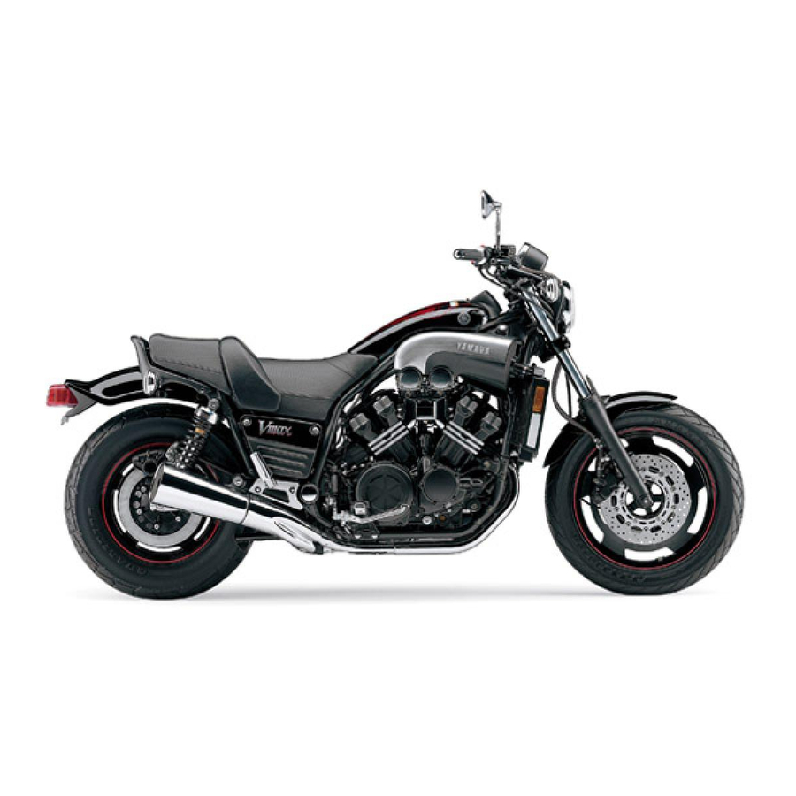
Summary of Contents for Yamaha VMAX VMX12
- Page 1 OWNER’S MANUAL VMX12 3LR-28199-E3...
- Page 3 EAU03338 Welcome to the Yamaha world of motorcycling! As the owner of VMX12, you are benefiting from Yamaha’s vast experience and new- est technology regarding the design and manufacture of high-quality products, which have earned Yamaha a reputation for dependability.
- Page 4 This manual should be considered a permanent part of this motorcycle and should remain with it even if the motorcycle is subsequently sold. Yamaha continually seeks advancements in product design and quality. Therefore, while this manual contains the most current product information available at the time of printing, there may be minor discrepancies between your motorcycle and this manual.
-
Page 5: Important Manual Information
IMPORTANT MANUAL INFORMATION EW000002 WARNING PLEASE READ THIS MANUAL CAREFULLY AND COMPLETELY BEFORE OPERATING THIS MOTORCYCLE. - Page 6 IMPORTANT MANUAL INFORMATION EAU03337 VMX12 OWNER’S MANUAL © 2000 by Yamaha Motor Co., Ltd. 1st Edition, April 2000 All rights reserved. Any reprinting or unauthorized use without the written permission of Yamaha Motor Co., Ltd. is expressly prohibited. Printed in Japan.
-
Page 7: Table Of Contents
EAU00009 TABLE OF CONTENTS 1 GIVE SAFETY THE RIGHT OF WAY 2 DESCRIPTION 3 INSTRUMENT AND CONTROL FUNCTIONS 4 PRE-OPERATION CHECKS 5 OPERATION AND IMPORTANT RIDING POINTS 6 PERIODIC MAINTENANCE AND MINOR REPAIR 7 MOTORCYCLE CARE AND STORAGE 8 SPECIFICATIONS 9 CONSUMER INFORMATION INDEX... -
Page 9: Give Safety The Right Of Way
GIVE SAFETY THE RIGHT OF WAY GIVE SAFETY THE RIGHT OF WAY ..........1-1... - Page 10 G IVE SAFETY THE RIGHT OF WAY EAU00021 Motorcycles are fascinating vehicles, which can give you an unsurpassed feeling of power and freedom. However, they also impose certain limits, which you must accept; even the best motorcycle does not ignore the laws of physics. Regular care and maintenance are essential for preserving value and operating condition of your motorcycle.
-
Page 11: Description
DESCRIPTION Left view ..................... 2-1 Right view................... 2-2 Controls and instruments ..............2-3... - Page 12 D ESCRIPTION EAU00026 Left view 1. Clutch master cylinder reservoir (page 6-27) 7. Rear shock absorber damping force 2. Air filter element (page 6-19) adjusting knob (page 3-13) 3. Fuse box (page 6-37) 8. Helmet holder (page 3-10) 4. Main fuse box (page 6-37) 9.
- Page 13 DESCRIPTION Right view 11. Fuel tank cap (page 3-7) 12. Battery (page 6-33) 13. Coolant reservoir (page 6-14) 14. Front brake master cylinder reservoir (page 6-27) 15. Main switch (page 3-1) 16. Radiator cap (page 6-16) 17. Radiator (page 6-16) 18.
- Page 14 DESCRIPTION Controls and instruments 1. Clutch lever (page 3-5) 2. Left handlebar switches (page 3-4) 3. Speedometer unit (page 3-2) 4. Right handlebar switches (page 3-4) 5. Brake lever (page 3-6) 6. Throttle grip (page 6-21) 7. Tachometer (page 3-3) 8.
-
Page 15: Instrument And Control Functions
INSTRUMENT AND CONTROL FUNCTIONS Main switch ............3-1 Fuel ..............3-8 Indicator and warning lights ........3-1 Starter (choke) lever ..........3-8 Speedometer unit ..........3-2 Steering lock ............3-9 Tachometer ............3-3 Rider seat ............3-9 Anti-theft alarm (optional) ........3-3 Helmet holder ............ 3-10 Coolant temperature gauge .........3-3 Adjusting the front fork ........ -
Page 16: Main Switch
I NSTRUMENT AND CONTROL FUNCTIONS EAU00027 1. Push. 1. Neutral indicator light “ ” 2. Release. 2. Turn signal indicator light “ ” EAU00028 3. Turn. 3. Fuel level warning light “ ” Main switch 4. High beam indicator light “ ”... -
Page 17: Instrument And Control Functions
1. Turn the key to “ON”. 2. If the warning light does not come EAU00063 High beam indicator light “ ” on, have a Yamaha dealer check 1. Tripmeter reset knob This indicator light comes on when the 2. Odometer the electrical circuit. -
Page 18: Tachometer
INSTRUMENT AND CONTROL FUNCTIONS EAU00109 Anti-theft alarm (optional) This motorcycle can be equipped with an optional anti-theft alarm by a Yamaha dealer. Contact a Yamaha dealer for more information. 1. Tachometer 1. Coolant temperature gauge 2. Red zone 2. Red zone... -
Page 19: Handlebar Switches
INSTRUMENT AND CONTROL FUNCTIONS EAU00124 Turn signal switch “ ” To signal a right-hand turn, push this switch to the right. To signal a left-hand turn, push this switch to the left. When released, the switch returns to the cen- ter position. -
Page 20: Clutch Lever
INSTRUMENT AND CONTROL FUNCTIONS EAU01653 Fuel reserve switch “FUEL” During normal operation, this switch should be kept in the “ON” position. If the fuel warning light comes on while riding, set the switch to “RES”, refuel as soon as possible, and then set the switch back to “ON”. -
Page 21: Shift Pedal
INSTRUMENT AND CONTROL FUNCTIONS 1. Shift pedal 1. Brake lever 1. Brake pedal EAU00157 EAU00158 EAU00162 Shift pedal Brake lever Brake pedal The shift pedal is located on the left The brake lever is located at the right The brake pedal is on the right side of side of the engine and is used in com- handlebar grip. -
Page 22: Fuel Tank Cap
INSTRUMENT AND CONTROL FUNCTIONS To install the fuel tank cap 1. Insert the fuel tank cap into the tank opening with the key inserted in the lock. 2. Turn the key counterclockwise, and then remove it. 3. Slide the rider seat backrest rear- ward and push it down. -
Page 23: Fuel
INSTRUMENT AND CONTROL FUNCTIONS EAU00185 CAUTION: Immediately wipe off spilled fuel with a clean, dry, soft cloth, since fuel may deteriorate painted surfac- es or plastic parts. EAU00191 Recommended fuel: 1. Filler tube 1. Starter (choke) lever Regular unleaded gasoline with a 2. -
Page 24: Steering Lock
INSTRUMENT AND CONTROL FUNCTIONS To unlock the steering 1. Open the steering lock cover, and then insert the steering lock steer- ing lock key. 2. Push the key in, turn it 1/8 turn counterclockwise so that it moves out, and then release it. 3. -
Page 25: Helmet Holder
INSTRUMENT AND CONTROL FUNCTIONS 1. Bolt ( 2) 1. Projection 1. Helmet holder 2. Screw ( 2) 2. Seat holder 2. Open. 2. Remove the bolts and screws, and To install the rider seat EAU00260 Helmet holder then pull the rider seat off. 1. -
Page 26: Adjusting The Front Fork
NOTE: NOTE: An optional air pressure gauge is avail- When checking and adjusting the air able at a Yamaha dealer. pressure, there should be no weight on 4. To increase the spring rate and the front end of the motorcycle. -
Page 27: Adjusting The Shock Absorber Assemblies
INSTRUMENT AND CONTROL FUNCTIONS EW000040 Spring rate: WARNING Minimum/standard (soft): Always adjust both shock absorber Air pressure = assemblies equally, otherwise poor 40 kPa (0.4 kg/cm , 0.4 bar) handling and loss of stability may Maximum (hard): result. Air pressure = 100 kPa (1.0 kg/cm , 1.0 bar) EC000012... - Page 28 INSTRUMENT AND CONTROL FUNCTIONS NOTE: Align the bottom edge of the ad- justing ring with the appropriate setting on the shock absorber. Use the special wrench included in the owner’s tool kit to make this adjustment. Spring preload: 1. Damping force adjusting knob Minimum (soft): 1 2.
- Page 29 INSTRUMENT AND CONTROL FUNCTIONS Damping force: Minimum (soft): 1 Standard: 1 Maximum (hard): 4 3-14...
-
Page 30: Matching The Front And Rear Suspension Settings
INSTRUMENT AND CONTROL FUNCTIONS EAU01658 Matching the front and rear suspension settings Use this table as a guide to match the suspension and damping adjustments of the front fork and shock absorber assembly according to various load conditions. CI-06E Load condition Front fork adjustment Shock absorber assembly adjustment Spring preload (air pressure) -
Page 31: Sidestand
It cuts the running engine when check this system regularly as de- the sidestand is moved down. scribed below and have a Yamaha Periodically check the operation of the dealer repair it if it does not function ignition circuit cut-off system according properly. - Page 32 5. Push the start switch. Does the engine start? The neutral switch may be defective. The motorcycle should not be ridden until checked by a Yamaha dealer. With the engine still running: 6. Move the sidestand up. 7. Keep the clutch lever pulled.
-
Page 33: Pre-Operation Checks
PRE-OPERATION CHECKS Pre-operation check list ..............4-1... -
Page 34: Pre-Operation Check List
P RE-OPERATION CHECKS EAU01114 The condition of a vehicle is the owner’s responsibility. Vital components can start to deteriorate quickly and unexpectedly, even if the vehicle remains unused (for example, as a result of exposure to the elements). Any damage, fluid leakage or loss of tire air pressure could have serious consequences. - Page 35 PRE-OPERATION CHECKS ITEM CHECKS PAGE • Make sure that all nuts, bolts and screws are properly tightened. Chassis fasteners — • Tighten if necessary. • Check fuel level. Fuel • Add fuel if necessary. Lights, signals and • Check operation. —...
-
Page 37: Operation And Important Riding Points
OPERATION AND IMPORTANT RIDING POINTS Starting a cold engine ............... 5-1 Starting a warm engine ..............5-3 Shifting ....................5-3 Recommended shift points (for Switzerland only) ......5-4 Tips for reducing fuel consumption ........... 5-4 Engine break-in ................. 5-4 Parking ....................5-5... -
Page 38: Starting A Cold Engine
Before starting engine, are poisonous, and inhaling Yamaha dealer check the electrical cir- check the function of the igni- them can cause loss of con- cuit. tion circuit cut-off system ac- sciousness and death within a 3. -
Page 39: Operation And Important Riding Points
Yamaha dealer check the off when the start switch is re- electrical circuit. leased. -
Page 40: Starting A Warm Engine
OPERATION AND IMPORTANT RIDING POINTS EAU01258 EC000048 Starting a warm engine CAUTION: Follow the same procedure as for start- Even with the transmission in ing a cold engine with the exception the neutral position, do not that the starter (choke) is not required coast for long periods of time when the engine is warm. -
Page 41: Recommended Shift Points (For Switzerland Only)
OPERATION AND IMPORTANT RIDING POINTS EAU02941 EAU00424 EAU00436 Recommended shift points Tips for reducing fuel Engine break-in (for Switzerland only) consumption There is never a more important period in the life of your engine than the period The recommended shift points during Fuel consumption depends largely on between 0 and 1,000 km. -
Page 42: Parking
Rev the engine freely through the motorcycle may overturn. If any engine trouble should gears, but do not use full throttle at occur during the engine break- any time. in period, immediately have a Yamaha dealer check 500–1,000 km vehicle. Avoid prolonged full-throttle oper- ation. -
Page 43: Periodic Maintenance And Minor Repair
PERIODIC MAINTENANCE AND MINOR REPAIR Owner’s tool kit ............6-1 Checking and lubricating the throttle grip and cable ..........6-29 Periodic maintenance and lubrication chart ..6-3 Checking and lubricating the brake and Removing and installing cowlings and panels ..6-6 shift pedals ............6-29 Checking the spark plugs ........6-7 Checking and lubricating the brake and Engine oil and oil filter cartridge ......6-9... -
Page 44: Owner's Tool Kit
If you do not have the tools or experi- If you are not familiar with motor- ence required for a particular job, have cycle maintenance work, have a a Yamaha dealer perform it for you. Yamaha dealer do it for you. - Page 45 PERIODIC MAINTENANCE AND MINOR REPAIR EW000063 WARNING Modifications approved Yamaha may cause loss of perfor- mance and render the vehicle un- safe for use. Consult a Yamaha dealer before attempting changes.
-
Page 46: Periodic Maintenance And Lubrication Chart
The annual checks must be performed every year, except if a kilometer-based maintenance is performed instead. From 50,000 km, repeat the maintenance intervals starting from 10,000 km. Items marked with an asterisk should be performed by a Yamaha dealer as they require special tools, data and techni- cal skills. - Page 47 PERIODIC MAINTENANCE AND MINOR REPAIR ODOMETER READING ( 1,000 km) ANNUAL ITEM CHECK OR MAINTENANCE JOB CHECK • Check for cracks or damage. Brake hoses • Replace. Every 4 years Wheels • Check runout and for damage. • Check tread depth and for damage. •...
- Page 48 PERIODIC MAINTENANCE AND MINOR REPAIR ODOMETER READING ( 1,000 km) ANNUAL ITEM CHECK OR MAINTENANCE JOB CHECK • Check oil level and vehicle for oil leakage. Final gear oil • Change. Front and rear brake • Check operation. switches Moving parts and cables • Lubricate. Lights, signals and •...
-
Page 49: Removing And Installing Cowlings And Panels
PERIODIC MAINTENANCE AND MINOR REPAIR 1. Cowling A 1. Unlock. 1. Holder ( 2) 2. Panel A 2. Projection ( 2) EAU03415 3. Panel B Cowling A To install the cowling EAU01139 To remove the cowling 1. Align the holders under the cowl- Removing and installing 1. -
Page 50: Checking The Spark Plugs
PERIODIC MAINTENANCE AND MINOR REPAIR 1. Screw ( 2) 1. Screw ( 2) 1. Spark plug cap EAU03340 EAU01315 EAU03329 Panel A Panel B Checking the spark plugs To remove the panel To remove the panel The spark plugs are important engine 1. - Page 51 Do not attempt to diagnose such problems yourself. Instead, have a Yamaha dealer check the motorcycle. 3. Check each spark plug for elec- trode erosion and excessive car- bon or other deposits, and replace 1.
-
Page 52: Engine Oil And Oil Filter Cartridge
PERIODIC MAINTENANCE AND MINOR REPAIR EAU02938 Tightening torque: Engine oil and oil filter Spark plug: cartridge 18 Nm (1.8 m·kg) The engine oil level should be checked before each ride. In addition, the oil NOTE: must be changed and the oil filter car- If a torque wrench is not available when tridge replaced at the intervals speci- installing a spark plug, a good estimate... - Page 53 An oil filter wrench is available at a Skip steps 4–6 if the oil filter cartridge is off. Yamaha dealer. not being replaced. 2. Place an oil pan under the engine to collect the used oil.
- Page 54 PERIODIC MAINTENANCE AND MINOR REPAIR 8. Add the specified amount of the recommended engine oil, and then install and tighten the oil filler cap. Recommended engine oil: See page 8-1. Oil quantity: Without oil filter cartridge 1. O-ring 1. Torque wrench replacement: 5.
- Page 55 (since the engine oil also or remains on, immediately turn the lubricates the clutch), do not engine off and have a Yamaha deal- mix any chemical additives with er check the vehicle. the oil or use oils of a higher 10.
-
Page 56: Final Gear Oil
The final gear case must be checked or multigrade hypoid gear oil for oil leakage before each ride. If any SAE 80W-90 leakage is found, have a Yamaha deal- Oil quantity: er check and repair the motorcycle. In 0.2 L... -
Page 57: Coolant
PERIODIC MAINTENANCE AND MINOR REPAIR EAU03416 NOTE: Coolant The coolant level must be checked The coolant level should be checked on a cold engine since the level before each ride. In addition, the cool- varies with engine temperature. ant must be changed at the intervals Make sure that the motorcycle is specified in the periodic maintenance positioned... - Page 58 If water has been added to the coolant, have a Yamaha dealer check the antifreeze content of the coolant as soon as possible, otherwise the effectiveness of the coolant will be reduced.
- Page 59 PERIODIC MAINTENANCE AND MINOR REPAIR 1. Radiator cap 1. Coolant drain cock 1. Water pump drain bolt 2. Position indicator 4. Remove the radiator cap. 6. Remove the water pump drain bolt 5. Turn the coolant drain cock to EW000067 to drain the water pump housing.
- Page 60 PERIODIC MAINTENANCE AND MINOR REPAIR Tightening torque: Water pump drain bolt: 43 Nm (4.3 m·kg) 11. Install the rubber coolant drain plugs, and then install the cylinder drain plug covers. NOTE: 1. Screw ( 4) 1. Rubber coolant drain plug ( 4) Check the rubber plugs for damage and replace them if necessary.
- Page 61 If wise the engine may not be coolant is leaking, have a Yamaha sufficiently cooled and the cool- dealer check the cooling system. ing system will not be protected 19.
-
Page 62: Cleaning The Air Filter Element
PERIODIC MAINTENANCE AND MINOR REPAIR EC000082 CAUTION: Make sure that the air filter ele- ment is properly seated in the air filter case. The engine should never be op- erated without the air filter ele- ment installed, otherwise the piston(s) and/or cylinder(s) may 1. -
Page 63: Adjusting The Carburetors
Therefore, most car- checked and, if necessary, adjusted as buretor adjustments should be left to a follows at the intervals specified in the Yamaha dealer, who has the neces- periodic maintenance and lubrication sary professional knowledge and expe- chart. -
Page 64: Adjusting The Throttle Cable Free Play
To prevent this your motorcycle, note the following from occurring, the valve clearance points regarding the specified tires. must be adjusted by a Yamaha dealer at the intervals specified in the periodic Tire air pressure maintenance and lubrication chart. - Page 65 Do not carry along loosely wall is cracked, have a Yamaha dealer packed items, which can shift replace the tire immediately. during a ride.
- Page 66 PERIODIC MAINTENANCE AND MINOR REPAIR EW000079 Tire information EAU00684 WARNING WARNING This motorcycle is equipped with tube Have a Yamaha dealer replace This motorcycle is fitted with super- tires. excessively worn tires. Besides high-speed tires. Note the following EW000078 WARNING...
-
Page 67: Cast Wheels
Valve stem locknut: damage before each ride. If any lever free play does become exces- 1.6 Nm (0.16 m·kg) damage is found, have a Yamaha sive, and shifting becomes rough or dealer replace the wheel. Do not clutch slippage occurs, causing poor... -
Page 68: Adjusting The Brake Lever Free Play
Yamaha necessary, adjust it as follows. dealer adjust it. 1. Loosen the locknut at the brake le- ver. -
Page 69: Adjusting The Rear Brake Light Switch
If there is air in the hydraulic system, have a Yamaha dealer bleed the system be- fore operating the motorcycle. Air in the hydraulic system will diminish 1. Brake light switch 1. -
Page 70: Checking The Brake Fluid Level
PERIODIC MAINTENANCE AND MINOR REPAIR Front brake Clutch Rear brake 1. Minimum level mark 1. Minimum level mark 1. Panel B 2. Minimum level mark EAU03418 NOTE: Checking the brake fluid level Refill with the same type of brake To check the rear brake fluid level, re- Insufficient brake fluid may allow air to fluid. -
Page 71: Changing The Brake Fluid
PERIODIC MAINTENANCE AND MINOR REPAIR Brake fluid may deteriorate paint- EAU03238 EAU02962 Changing the brake fluid Checking and lubricating the ed surfaces or plastic parts. Al- Have a Yamaha dealer change the cables ways clean spilled fluid brake fluid at the intervals specified in The operation of all control cables and immediately. -
Page 72: Checking And Lubricating The Throttle Grip And Cable
PERIODIC MAINTENANCE AND MINOR REPAIR EAU03209 Checking and lubricating the Recommended lubricant: Throttle cable: throttle grip and cable Engine oil The operation of the throttle grip and Throttle grip housing and grip: the condition of the throttle cable Lithium-soap-based grease should be checked before each ride, (all-purpose grease) and the cable should be lubricated or... -
Page 73: Checking And Lubricating The Brake And Clutch Levers
Recommended lubricant: EW000114 WARNING Lithium-soap-based grease If the centerstand or sidestand does (all-purpose grease) not move up and down smoothly, have a Yamaha dealer check or re- pair it. 6-30... -
Page 74: Lubricating The Rear Suspension
Recommended lubricant: bounds smoothly. Lithium-soap-based grease EC000098 (all-purpose grease) CAUTION: If any damage is found or the front fork does not operate smoothly, have a Yamaha dealer check or re- pair it. 6-31... -
Page 75: Checking The Steering
WARNING ward and backward. If any free Securely support the motorcycle so play can be felt, have a Yamaha that there is no danger of it falling dealer check or repair the steer- over. -
Page 76: Checking The Wheel Bearings
If there is play in the wheel hub or if the wheel does not turn smoothly, have a Yamaha dealer check the wheel bearings. 1. Battery 1. Maximum level mark 2. - Page 77 PERIODIC MAINTENANCE AND MINOR REPAIR 3. If the electrolyte is at or below the minimum level mark, continue with the following steps. 1. Bolt ( 2) 1. Starter motor lead (black) 2. Screw ( 2) 2. Battery positive lead (red) 3.
- Page 78 PERIODIC MAINTENANCE AND MINOR REPAIR EW000116 KEEP THIS AND ALL BATTER- WARNING IES OUT OF THE REACH OF Electrolyte is poisonous and CHILDREN. dangerous since it contains sul- EC000100 furic acid, which causes severe CAUTION: burns. Avoid any contact with Use only distilled water, as tap water skin, eyes or clothing and al- contains minerals that are harmful...
- Page 79 PERIODIC MAINTENANCE AND MINOR REPAIR To store the battery EC000099 CAUTION: 1. If the motorcycle will not be used If the breather hose is positioned in for more than one month, remove such a way that the frame is ex- the battery, fully charge it, and posed to electrolyte or gas expelled then place it in a cool, dry place.
-
Page 80: Replacing The Fuses
4. If the fuse immediately blows EAU01664 4. Radiator fan fuse Replacing the fuses again, have a Yamaha dealer 5. Spare fuse ( 2) The main fuse box is located under the check the electrical system. rider seat. (See page 3-9 for rider seat Specified fuses: removal and installation procedures.) -
Page 81: Replacing The Headlight Bulb
4. Place a new bulb into position, and 5. Install the bulb cover, and then then secure it with the bulb holder. connect the coupler. 6. Install the headlight unit by install- ing the screws. 7. Have a Yamaha dealer adjust the headlight beam if necessary. 6-38... -
Page 82: Replacing A Turn Signal Light Bulb Or The Tail
PERIODIC MAINTENANCE AND MINOR REPAIR 1. Screw ( 2) 1. Tail/brake light bulb ( 2) 1. Turn signal light bulb 3. Insert a new bulb into the socket, 4. Install the lens by installing the EAU00855 Replacing a turn signal light push it in, and then turn it clock- screws. -
Page 83: Front Wheel
PERIODIC MAINTENANCE AND MINOR REPAIR EAU03419 Front wheel To remove the front wheel EW000122 WARNING It is advisable to have a Yamaha dealer service the wheel. Securely support the motor- cycle so that there is no danger 1. Speedometer cable 2. Bolt ( 2) of it falling over. -
Page 84: Rear Wheel
WARNING 58 Nm (5.8 m·kg,) the fork leg. It is advisable to have a Yamaha Front wheel axle pinch bolt: dealer service the wheel. 3. Insert the wheel axle. 20 Nm (2.0 m·kg) Securely support the motor- 4. - Page 85 PERIODIC MAINTENANCE AND MINOR REPAIR 1. Pinch bolt 1. Nut 2. Cotter pin 1. Loosen the rear wheel axle pinch 5. While supporting the brake cali- 3. Brake torque rod bolt, then the axle nut. per, pull the wheel axle out. 4.
- Page 86 PERIODIC MAINTENANCE AND MINOR REPAIR 4. Install the brake torque rod bolt EW000124 WARNING and nut at the brake caliper brack- Always use a new cotter pin. 5. Install the rear wheel axle nut. 6. Take the motorcycle off the cen- terstand so that the rear wheel is on the ground.
-
Page 87: Troubleshooting
The following troubleshooting charts represent quick and easy procedures for checking these vital systems your- self. However, should your motorcycle require any repair, take it to a Yamaha dealer, whose skilled technicians have the necessary tools, experience, and know-how to service the motorcycle properly. -
Page 88: Troubleshooting Charts
Remove the spark plugs and check the electrodes. The engine does not start. Have a Yamaha dealer check the vehicle. Check the battery. 4. Battery The engine turns over The battery is good. - Page 89 Start the engine. If the engine overheats again, have a The coolant level Yamaha dealer check and repair the cooling system. is OK. NOTE: If coolant is not available, tap water can be temporarily used instead, provided that it is changed to the recommended coolant as soon as possible.
-
Page 91: Motorcycle Care And Storage
MOTORCYCLE CARE AND STORAGE Care ....................7-1 Storage ....................7-4... - Page 92 M OTORCYCLE CARE AND STORAGE EAU03412 Care Before cleaning Cleaning 1. Cover the muffler outlets with plas- ECA00010 While the open design of a motorcycle CAUTION: tic bags after the engine has reveals the attractiveness of the tech- Avoid using strong acidic wheel cooled down.
- Page 93 MOTORCYCLE CARE AND STORAGE thinner, fuel (gasoline), rust re- shield is scratched, use a quali- After riding in the rain, near the sea or movers or inhibitors, brake flu- ty plastic polishing compound on salt-sprayed roads id, antifreeze or electrolyte. after washing.
- Page 94 NOTE: including chrome- and nickel-plat- Consult a Yamaha dealer for advice on ed, surfaces. what products to use. 4. Use spray oil as a universal clean- er to remove any remaining dirt. 5. Touch up minor paint damage caused by stones, etc.
- Page 95 MOTORCYCLE CARE AND STORAGE Storage Long-term c. Install the spark plug caps onto the Before storing your motorcycle for sev- spark plugs, and then place the eral months: spark plugs on the cylinder head Short-term 1. Follow all the instructions in the so that the electrodes are ground- Always store your motorcycle in a cool, “Care”...
- Page 96 MOTORCYCLE CARE AND STORAGE 6. Lubricate all control cables and NOTE: Make any necessary repairs before the pivoting points of all levers and storing the motorcycle. pedals as well as of the sidestand/ centerstand. 7. Check and, if necessary, correct the tire air pressure, and then lift the motorcycle so that both of its wheels are off the ground.
-
Page 97: Specifications
SPECIFICATIONS Specifications ..................8-1 Conversion table ................8-5... -
Page 98: Specifications
S PECIFICATIONS EAU01038 Specifications CS-01E Model VMX12 Engine oil Dimensions Type -20 -10 10 20 30 40 50 ˚C Overall length 2,300 mm SAE 10W-30 Overall width 795 mm SAE 10W-40 Overall height 1,160 mm Seat height 765 mm SAE 15W-40... - Page 99 SPECIFICATIONS Final gear oil Operation Left foot Type SAE80API “GL-4” Hypoid gear Gear ratio 2.529 Quantity 0.2 L 1.773 Cooling system capacity 1.348 (total amount) 3.05 L 1.077 Air filter Dry type element 0.929 Fuel Chassis Type Regular unleaded gasoline Frame type Double cradle Fuel tank capacity...
- Page 100 SPECIFICATIONS Maximum load* 209 kg Rear Tire air pressure (measured Type Single disc brake on cold tires) Operation Right foot Up to 90 kg* Fluid DOT 4 Front 225 kPa (2.25 kg/cm , 2.25 bar) Suspension Rear 225 kPa (2.25 kg/cm , 2.25 bar) Front Telescopic fork...
- Page 101 SPECIFICATIONS Bulb voltage, wattage quantity Headlight 12 V, 60/55 W Tail/brake light 12 V, 5/21 W Turn signal light 12 V, 21 W Auxiliary light 12 V, 3.4 W 1 (for GB) 12 V, 4 W 1 (for F, B, I, P) Meter lighting 14 V, 3 W Neutral indicator light...
-
Page 102: Conversion Table
SPECIFICATIONS EAU01064 Conversion table CS-02E Conversion table All specification data in this manual are listed in SI and METRIC TO IMPERIAL METRIC UNITS. Metric unit Multiplier Imperial unit Use this table to convert METRIC unit data to IMPERIAL m·kg 7.233 ft·lb m·kg 86.794... -
Page 103: Consumer Information
CONSUMER INFORMATION Identification numbers ............... 9-1 Key identification number ..............9-1 Vehicle identification number ............. 9-1 Model label ..................9-2... -
Page 104: Identification Numbers
Record the key identification number, vehicle identification number and mod- el label information in the spaces pro- vided below for assistance when ordering spare parts from a Yamaha dealer or for reference in case the vehi- cle is stolen. 1. Key identification number 1. -
Page 105: Model Label
The model label is affixed under cowl- ing A. (See page 6-6 for cowling re- moval and installation procedures.) Record the information on this label in the space provided. This information will be needed when ordering spare parts from a Yamaha dealer. - Page 106 I NDEX 1 0 - Cowlings and panels, removing and installing ..........6-6 Air filter element, cleaning ......6-19 Key identification number ......9-1 Anti-theft alarm ........3-3 Dimmer switch......... 3-4 Light switch ..........3-4 Battery ...........6-33 Brake and clutch levers, checking and Engine break-in ........5-4 Main switch ..........3-1 lubricating ..........6-30 Engine oil and oil filter cartridge ....
-
Page 107: Throttle Grip
INDEX Speedometer unit ........3-2 Starter (choke) lever ........ 3-8 Wheel bearings, checking ..... 6-33 Starting a cold engine ......5-1 Wheel (front) ......... 6-40 Starting a warm engine......5-3 Installing .......... 6-40 Start switch..........3-5 Removing ........6-40 Steering, checking ......... 6-32 Wheel (rear) .......... - Page 110 YAMAHA MOTOR CO., LTD. PRINTED ON RECYCLED PAPER PRINTED IN JAPAN 2000 · 10 - 0.3 1 CR...