Table of Contents
Advertisement
Quick Links
Advertisement
Table of Contents

Related Manuals for Zanussi ZGF 646 ICX


Summary of Contents for Zanussi ZGF 646 ICX
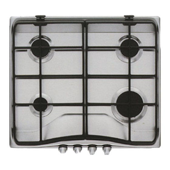
- Page 1 GAS HOBS ZGF 646 ICX ZGF 646 ICW OPERATING AND INSTALLATION MANUAL...
-
Page 2: For Your Safety
• In case of intensive or long time use of the malfunctioning. Refer to your local Zanussi Service appliance, make the ventilation more efficient, by Centre. Always insist on genuine Zanussi spare opening a window or increasing the electric parts. -
Page 3: Table Of Contents
Contents 1. Instruction for the User .... Pag. 5. Technical Data ......Pag. 2. Cleaning and Maintenance ..Pag. 6. Instruction for the Installer ..Pag. 3. Periodic Maintenance ....Pag. 7. Electrical Connection....Pag. 8. Adaptation to different 4. Maintenance - types of gas ....... -
Page 4: Cleaning And Maintenance
THE HOB LID In order to make the appliance match with the kitchen Always clean the lid from cooking residues before design, a lid (not provided) can be fitted on the hob. opening it or taking it off. The lid is meant to avoid dust to settle on the hob, WARNING! The crystal lid can splinter when when it is closed, and to collect splashes of oil or overheated. -
Page 5: Periodic Maintenance
ENAMELLED PAN SUPPORTS In hobs provided with enamelled pan supports, these can be removed and kept in the right position thanks to special hinges in the back of the hob (see fig. 4 and 5). This solution enables rapid and easy cleaning of the hob. -
Page 6: Technical Data
5. Technical Data Gas Burners Rating Rapid Burner (big) 2,8 kW (G30/G31) - 3 kW (G20) Gas connection G 1/2" Semirapid Burner (medium) 2 kW Electric Supply 230 V 50 Hz Auxiliary Burner (small) 1 kW HOB RECESS DIMENSIONS Category II 2H 3+ Length 560 mm. -
Page 7: Electrical Connection
7. Electrical Connection The appliance is designed to be connected to 230 V monophase electricity supply. The connection must be carried out in compliance with the laws and regulations in force. Before the appliance is connected: 1) check that the main fuse and the domestic installation can support the load (see the rating label);... -
Page 8: Adaptation To Different Types Of Gas
8. Adaptation to different types of gas REPLACEMENT OF INJECTORS • Remove the pan supports. • Remove the burner's caps and crowns. • With a socket spanner 7 unscrew and remove the injectors (Fig. 9), and replace them with the ones required for the type of gas in use (see table on the next page). -
Page 9: Building In
9. Building In A = Auxiliary burner SR = Semirapid burner Fig. 11 R = Rapid Burner These hobs can be inserted in a built-in kitchen unit whose depth is between 550 and 600 mm. The hobs dimensions are shown in Fig. 11. FITTING THE LID We recommend the lid hinge block are fitted before installing the hob into the worktop. - Page 10 INSTALLATION AND ASSEMBLY These hobs can be installed in a kitchen unit with an opening for insertion whose dimensions are shown in Fig. 15. The edge of the cut out must have a minimum distance from the rear wall of 55 mm. If there are side walls, or sides of the furniture unit near the hob, the cut out edges must have a minimum distance of 100 mm.
- Page 11 POSSIBILITIES FOR Fig. 19 Fig. 18 INSERTION Kitchen unit with door Proper arrangements must be taken in designing the forniture unit, in order to avoid any contact with the bottom of the hob which can be heated when it is operated. The recommended solution is shown in Fig.
- Page 12 From the Electrolux Group. The world’s No.1 choice. The Electrolux Group is the world’s largest producer of powered appliances for kitchen, cleaning and outdoor use. More than 55 million Electrolux Group products (such as refrigerators, cookers, washing machines, vacuum cleaners, chain saws and lawn mowers) are sold each year to a value of approx.