D-Link DES-3350SR User Manual
Standalone layer 3 switch
Hide thumbs
Also See for DES-3350SR:
- Command line interface reference manual (379 pages) ,
- Reference manual (486 pages)
Table of Contents
Advertisement
Quick Links
Advertisement
Table of Contents

Related Manuals for D-Link DES-3350SR


Summary of Contents for D-Link DES-3350SR
- Page 1 D-Link ™ DES-3350SR Standalone Layer 3 Switch User’s Guide...
- Page 2 Microsoft Corporation. Other trademarks and trade names may be used in this document to refer to either the entities claiming the marks and names or their products. D-Link Computer Corporation disclaims any proprietary interest in trademarks and trade names other than its own.
-
Page 3: Table Of Contents
D-Link DES-3350SR Standalone Layer 3 Switch Table of Contents Preface ................................vi Intended Readers ............................vi Notes, Notices, and Cautions........................vi Safety Instructions ............................ vii General Precautions for Rack-Mountable Products ................viii Protecting Against Electrostatic Discharge .....................viii Introduction ............................... 1 Fast Ethernet Technology ..........................1 Gigabit Ethernet Technology.......................... - Page 4 D-Link DES-3350SR Standalone Layer 3 Switch MIBs ................................. 13 IP Address Assignment..........................13 Connecting Devices to the Switch........................ 14 Web-based Switch Management ........................16 Introduction..............................16 Login to Web Manager..........................16 User Accounts Management......................... 16 Admin and User Privileges........................17 Save Changes..............................17 Areas of the User Interface ...........................
- Page 5 D-Link DES-3350SR Standalone Layer 3 Switch Secure Shell (SSH) ............................81 SNMP ................................85 SNMP User Table............................. 85 SNMP View Table............................ 87 SNMP Group Table ..........................88 SNMP Community Table ......................... 89 SNMP Host Table............................. 90 SNMP Engine ID............................91 Layer 3 IP Networking ..........................92...
- Page 6 D-Link DES-3350SR Standalone Layer 3 Switch OSPF Monitoring............................147 OSPF LSDB Table ..........................147 OSPF Neighbor Table..........................148 OSPF Virtual Neighbor .......................... 148 DVMRP Monitoring........................... 148 DVMRP Routing Table .......................... 149 DVMRP Neighbor Table........................149 DVMRP Routing Next Hop Table ......................149 PIM Monitoring ............................
-
Page 7: Preface
Appendix B, Understanding and Troubleshooting Spanning Tree Protocol - A detailed description of Spanning tree Protocol. Intended Readers The DES-3350SR User’s Guide contains information for setup and management of the DES-3350SR switch. This guide is intended for network managers familiar with network management concepts and terminology. -
Page 8: Safety Instructions
D-Link DES-3350SR Standalone Layer 3 Switch Safety Instructions Use the following safety guidelines to ensure your own personal safety and to help protect your system from potential damage. Throughout this safety section, the caution icon is used to indicate cautions and precautions that you need to review and follow. -
Page 9: General Precautions For Rack-Mountable Products
D-Link DES-3350SR Standalone Layer 3 Switch • If the system has multiple sources of power, disconnect power from the system by • Unplug all power cables from the power supplies. • Move products with care; ensure that all casters and/or stabilizers are firmly connected to the system. Avoid sudden stops and uneven surfaces. - Page 10 D-Link DES-3350SR Standalone Layer 3 Switch 1. When unpacking a static-sensitive component from its shipping carton, do not remove the component from the antistatic packing material until you are ready to install the component in your system. Just before unwrapping the antistatic packaging, be sure to discharge static electricity from your body.
-
Page 11: Introduction
Switch Stacking Performance Features Ports This section describes the functionality features of the DES-3350SR. Fast Ethernet Technology 100Mbps Fast Ethernet (or 100BASE-T) is a standard specified by the IEEE 802.3 LAN committee. It is an extension of the 10Mbps Ethernet standard with the ability to transmit and receive data at 100Mbps, while maintaining the Carrier Sense Multiple Access with Collision Detection (CSMA/CD) Ethernet protocol. -
Page 12: Software Features
D-Link DES-3350SR Standalone Layer 3 Switch Software Features Switch software features include: • Classification based on 802.1P Priority • Number of priority queues supported • Based on TOS field on IP header • DSCP • Classification based on IP Destination and Source Addresses (Based on Layer 3 information) •... -
Page 13: Mib Support
D-Link DES-3350SR Standalone Layer 3 Switch • Support Port Security function • Support Cisco-like Port Security function • Web GUI Traffic Monitoring • Web MAC address browsing • SNMP Trap on MAC Notification • Delete individual IP address by dynamic learning (ARP table editing) •... - Page 14 D-Link DES-3350SR Standalone Layer 3 Switch • Based on VLAN • Based on IP address • Based on TCP/UDP port number • Based on 802.1p priority • Based on DSCP...
-
Page 15: Unpacking And Setup
Rack Installation The DES-3350SR can be mounted in an EIA standard-sized, 19-inch rack, which can be placed in a wiring closet with other equipment. To install, attach the mounting brackets on the switch’s side panels (one on each side) and secure them with the screws... -
Page 16: Power On
Power on The DES-3350SR switch can be used with AC power supply 100 - 240 VAC, 50 - 60 Hz. The power switch is located at the rear of the unit adjacent to the AC power connector and the system fan. The switch’s power supply will adjust to the local power source automatically and may be turned on without having any or all LAN segment cables connected. -
Page 17: Identifying External Components
D-Link DES-3350SR Standalone Layer 3 Switch Section 3 Identifying External Components Front Panel Rear Panel Side Panels Gigabit Combo Ports LED Indicators This chapter describes the front panel, rear panel, side panels, and optional plug-in module, and LED indicators of the DES- 3350SR. -
Page 18: Gigabit Combo Ports
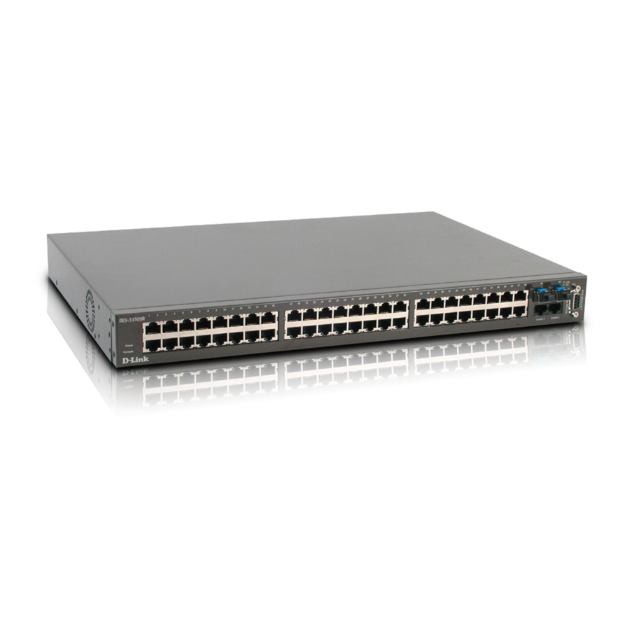
D-Link DES-3350SR Standalone Layer 3 Switch Gigabit Combo Ports In addition to the 48 10/100 Mbps ports, the Switch features two Gigabit Ethernet Combo ports. These two ports are 1000BASE-T copper ports (provided) and Mini-GBIC ports (optional). See the diagram below to view the two Mini-GBIC port modules being plugged into the Switch. -
Page 19: Connecting The Switch
Switch to Hub or Switch 10BASE-T Device 100BASE-TX Device This chapter describes how to connect the DES-3350SR to your Ethernet/Fast Ethernet/Gigabit Ethernet network. The Switch’s auto-detection feature allows all 48 10/100 ports to support both MDI-II and MDI-X connections. Switch to End Node End nodes include PCs outfitted with a 10, 100, or 10/100 Mbps RJ-45 Ethernet/Fast Ethernet Network Interface Card (NIC) and most routers. -
Page 20: Introduction To Switch Management
D-Link DES-3350SR Standalone Layer 3 Switch Section 5 Introduction to Switch Management Management Options Web-based Management Interface SNMP-Based Management Managing User Accounts Command Line Console Interface through the Serial Port Connecting the Console Port (RS-232 DCE) First Time Connecting to The Switch... -
Page 21: First Time Connecting To The Switch
12. Enter the commands to complete your desired tasks. Many commands require administrator-level access privileges. Read the next section for more information on setting up user accounts. See the DES-3350SR Command Line Interface Reference Manual on the documentation CD for a list of all commands and additional information on using the CLI. -
Page 22: Password Protection
Password Protection The DES-3350SR does not have a default user name and password. One of the first tasks when settings up the Switch is to create user accounts. If you log in using a predefined administrator-level user name, you have privileged access to the Switch's management software. -
Page 23: Snmp Settings
The DES-3350SR supports SNMP versions 1, 2c, and 3. You can specify which version of SNMP you want to use to monitor and control the Switch. The three versions of SNMP vary in the level of security provided between the management station and the network device. -
Page 24: Connecting Devices To The Switch
D-Link DES-3350SR Standalone Layer 3 Switch Figure 5 - 5. Show switch command The Switch's MAC address can also be found from the Web management program on the Switch Information (Basic Settings) window on the Configuration menu. The IP address for the Switch must be set before it can be managed with the Web-based manager. The Switch IP address can be automatically set using BOOTP or DHCP protocols, in which case the actual address assigned to the Switch must be known. - Page 25 D-Link DES-3350SR Standalone Layer 3 Switch NOTICE: When the SFP transceiver acquires a link, the associated integrated 10/100/1000BASE-T port is disabled.
-
Page 26: Web-Based Switch Management
Web Pages Introduction The DES-3350SR offers an embedded Web-based (HTML) interface allowing users to manage the switch from anywhere on the network through a standard browser such as Netscape Navigator/Communicator or Microsoft Internet Explorer. The Web browser acts as a universal access tool and can communicate directly with the Switch using the HTTP protocol. -
Page 27: Admin And User Privileges
Save Changes The DES-3350SR has two levels of memory; normal RAM and non-volatile or NV-RAM. Configuration changes are made effective by clicking the Apply button. When this is done, the settings will be immediately applied to the switching software in RAM, and will immediately take effect. -
Page 28: Areas Of The User Interface
D-Link DES-3350SR Standalone Layer 3 Switch Figure 6 - 4. Save Configuration window Click the Save Configuration button to save the current switch configuration in NV-RAM. The following dialog box will confirm that the configuration has been saved: Figure 6 - 5. Save Configuration Confirmation dialog box Click the OK button to continue. -
Page 29: Web Pages
D-Link DES-3350SR Standalone Layer 3 Switch functions, including the ports, expansion modules, management module, or the case. Allows the selection of commands. Presents switch information based on your selection and the entry of configuration data. NOTICE: Any changes made to the Switch configuration during the... -
Page 30: Configuration
Access Profile Table IP-MAC Binding PAE Access Entity This section, arranged by topic, describes how to perform common configuration tasks on the DES-3350SR switch using the Web- based Manager. IP Address The Switch needs to have an IP address assigned to it so that an In-Band network management system (for example, the Web Manager or Telnet) client can find it on the network. - Page 31 D-Link DES-3350SR Standalone Layer 3 Switch Parameter Description The switch will send out a BOOTP broadcast BOOTP request when it is powered up. The BOOTP protocol allows IP addresses, network masks, and default gateways to be assigned by a central BOOTP server. If this option is set, the...
-
Page 32: Switch Information
D-Link DES-3350SR Standalone Layer 3 Switch “System” to be enabled or disabled. Switch Information Click the Switch Information link in the Configuration menu. Figure 7 - 2. Switch Information (Basic Settings) window This window shows which (if any) external modules are installed, and the switch’s MAC Address (assigned by the factory and unchangeable). -
Page 33: Port Description
D-Link DES-3350SR Standalone Layer 3 Switch logging out. The default for this setting is 10 minutes. MAC Address Aging The MAC Address Aging Time specifies the Time <300> length of time a learned MAC Address will remain in the forwarding table without being accessed (that is, how long a learned MAC Address is allowed to remain idle). -
Page 34: Port Configuration
D-Link DES-3350SR Standalone Layer 3 Switch Figure 7 - 4. Port Description Settings window Use the From and To pull down menu to choose a port or range of ports to describe and Unit to choose the Switch in the switch stack, and then enter a description of the port(s). - Page 35 Use the Speed/Duplex pull-down menu to select the speed and duplex/half-duplex state of the port. The Auto setting allows the port to automatically determine the fastest settings the port on the device connected to the DES-3350SR can handle, and then use those settings.
-
Page 36: Port Mirroring
D-Link DES-3350SR Standalone Layer 3 Switch Auto setting allows the port to automatically determine the fastest settings the device the port is connected to can handle, and then to use those settings. The other options are 100M/Full, 100M/Half, 10M/Full, and 10M/Half. There is no automatic adjustment of port settings with any option other than Auto. -
Page 37: Igmp
D-Link DES-3350SR Standalone Layer 3 Switch Status Toggle between Enabled and Disabled. IGMP IGMP Snooping From the Configuration menu, select the IGMP folder, and then click IGMP Snooping to open the following window: Figure 7 - 7. Current IGMP Snooping Group Entries window To edit an IGMP Snooping entry on the switch, click the Modify button next to the entry on the Current IGMP Snooping Group Entries window. -
Page 38: Static Router Ports Entry
D-Link DES-3350SR Standalone Layer 3 Switch packets. A value between 2 and 255 can be entered, with larger values being specified for VLANs that are expected to lose larger numbers of packets. Specifies the maximum amount of time Last Member Query... -
Page 39: Spanning Tree
D-Link DES-3350SR Standalone Layer 3 Switch Figure 7 - 10. Static Router Ports Settings window The following fields are displayed: Parameter Description Displays the name of the VLAN ID the static router port belongs to. VLAN Name Displays the name of the VLAN the static router port belongs to. -
Page 40: Stp Switch Settings
D-Link DES-3350SR Standalone Layer 3 Switch RSTP is capable of more rapid transition to a forwarding state – it no longer relies on timer configurations – RSTP-compliant bridges are sensitive to feedback from other RSTP-compliant bridge links. Ports do not need to wait for the topology to stabilize before transitioning to a forwarding state. -
Page 41: Stp Port Settings
D-Link DES-3350SR Standalone Layer 3 Switch Note: The factory default setting should cover the majority of installations. It is advisable to keep the default settings as set at the factory unless it is absolutely necessary to change them. The following fields can be set:... - Page 42 D-Link DES-3350SR Standalone Layer 3 Switch Figure 7 - 12. STP Port Settings window In addition to setting Spanning Tree parameters for use on the switch level, the switch allows for the configuration of a group of ports. This STP Group will use the switch-level parameters entered above, with the addition of Port Priority and Port Cost.
-
Page 43: Unicast Forwarding
D-Link DES-3350SR Standalone Layer 3 Switch probability the port will be chosen to forward packets. Default port cost: 100Mbps port = 200000 Gigabit ports = 20000 Priority A Port Priority can be from 0 to 240. The lower the number, the greater the probability the port will be chosen as the Root Port. -
Page 44: Multicast Forwarding
D-Link DES-3350SR Standalone Layer 3 Switch switch’s static forwarding table when adding a new entry. Displays the currently selected MAC address when editing. Allows the selection of the port number on Allowed to Go Port which the MAC address entered above resides. -
Page 45: Vlans
VLANs on the DES-3350SR The DES-3350SR supports IEEE 802.1Q VLANs. The port untagging function can be used to remove the 802.1Q tag from packet headers to maintain compatibility with devices that are tag-unaware (that is, network devices that do not support IEEE 802.1Q VLANs or tagging). -
Page 46: Static Vlan Entry
D-Link DES-3350SR Standalone Layer 3 Switch Figure 7 - 17. IEEE 802.1Q Tag The EtherType and VLAN ID are inserted after the MAC source address, but before the original EtherType/Length or Logical Link Control. Because the packet is now a bit longer than it was originally, the Cyclic Redundancy Check (CRC) must be recalculated. - Page 47 D-Link DES-3350SR Standalone Layer 3 Switch Figure 7 - 20. (Add) 802.1Q Static VLAN window To edit an existing 802.1Q VLAN, click the corresponding Modify button on the 802.1Q Static VLANs window. The following window will open: Figure 7 - 21. (Modify) 802.1Q Static VLAN window The following fields can then be set in either of the two 802.1Q Static VLAN windows:...
-
Page 48: Port Vlan Id(Pvid)
D-Link DES-3350SR Standalone Layer 3 Switch Advertising can be enabled or disabled Advertisement using this pull-down menu. Advertising allows members to join this VLAN through GVRP. Allows an individual port to be specified Port Settings as member of a VLAN. -
Page 49: Ingress Checking
D-Link DES-3350SR Standalone Layer 3 Switch Ports with tagging enabled will put the VID number, priority and other VLAN information into the header of all packets that flow into and out of it. If a packet has previously been tagged, the port will not alter the packet, thus keeping the VLAN information intact. - Page 50 D-Link DES-3350SR Standalone Layer 3 Switch Figure 7 - 22. 802.1Q Port Settings window The following fields can be set: Parameter Description Enter the desired ports in these two From and To fields. A Port VLAN Identifier is a classification...
-
Page 51: Port Bandwidth
D-Link DES-3350SR Standalone Layer 3 Switch The Group VLAN Registration Protocol GVRP <Disabled> (GVRP) enables the port to dynamically become a member of a VLAN. This field can be toggled using the space Ingress <Disabled> bar between Enabled and Disabled. -
Page 52: Sntp Settings
SNTP Settings The DES-3350SR supports Simple Network Time Protocol (SNTP), an adaptation of the Network Time Protocol (NTP). As specified in RFC-1305 [MIL92], NTP is used to synchronize computer clocks in the global Internet. It provides comprehensive mechanisms to access national time and frequency dissemination services, organize the time-synchronization subnet, and adjust the local clock in each participating subnet peer. -
Page 53: Current Time Settings
D-Link DES-3350SR Standalone Layer 3 Switch Current Time Settings To enable SNTP on the Switch, click SNTP Settings in the Configuration folder and then click Current Time Settings: Figure 7 - 24. Current Time window To use SNTP, toggle the SNTP State in the Current Time: SNTP Settings section to Enabled and enter the IP address of the relay the SNTP Primary Server and/or the SNTP Secondary Server. -
Page 54: Port Security
D-Link DES-3350SR Standalone Layer 3 Switch Figure 7 - 25. Time Zone and DST Settings window This window allows you to set the Daily Saving Time repeated and annual settings. Click Apply to let your changes take effect. Port Security A given port’s (or a range of port’s) dynamic MAC address learning can be locked such that the current source MAC addresses... - Page 55 D-Link DES-3350SR Standalone Layer 3 Switch Figure 7 - 26. Port Security Settings window The following fields can be set: Parameter Description From & To Use this to specify a consecutively numbered group of ports on the switch for configuration.
-
Page 56: Qos (Quality Of Service)
The possible range for maximum packets is: 0 to 255 packets. The possible range for maximum latency is: 0 to 255 (in increments of 16 microseconds each). Remember that the DES-3350SR has four priority queues (and thus four Classes of Service) for each port on the switch. Traffic Control This window allows you to manage traffic control on the switch. -
Page 57: 802.1P Default Priority
D-Link DES-3350SR Standalone Layer 3 Switch Switch’s reaction to Broadcast storms, triggered at the threshold set in the last field. Multicast Storm This field can be toggled between Enabled <Disabled> and Disabled using the drop-down menu. This enables or disables, globally, the Switch’s reaction to Multicast storms,... -
Page 58: 802.1P User Priority
0 − the lowest priority − to 7 − the highest priority. 802.1p User Priority The DES-3350SR allows the assignment of a Class of Traffic to each of the 802.1p priorities. Click 802.1p user_priority in the QoS folder on the Configuration menu:... -
Page 59: Scheduling
D-Link DES-3350SR Standalone Layer 3 Switch Figure 7 - 29. QoS Class of Traffic window Once you have assigned a maximum number of packets and a maximum latency to a given Class of Service on the switch, you can then assign this Class to each of the eight levels of 802.1p priorities. -
Page 60: Lacp
The DES-3350SR supports link aggregation groups, which may include from two to eight switch ports each, except for a Gigabit link aggregation group which consists of the two (optional) Gigabit Ethernet ports of the front panel. - Page 61 D-Link DES-3350SR Standalone Layer 3 Switch Figure 7 - 32. Link Aggregation Group Data transmitted to a specific host (destination address) will always be transmitted over the same port in a link aggregation group. This allows packets in a data stream to arrive in the same order they were sent. An aggregated link connection can be made with any other switch that maintains host-to-host data streams over a single link aggregate port.
- Page 62 D-Link DES-3350SR Standalone Layer 3 Switch Figure 7 - 34. Port Link Aggregation Settings (Add) window Figure 7 - 35. Port Link Aggregation Settings (Modify) window The following fields can be set: Parameter Description Allows the entry of a number used to Group ID(1-6) identify the link aggregation group −...
-
Page 63: Lacp Port
LACP Port The DES-3350SR supports Link Aggregation Control Protocol. LACP allows you to bundle several physical ports together to form one logical port. After the LACP negotiation, these candidates for trunking ports can be trunked as a logical port. If any one of the connected port pairs does not have LACP capability, these two ports will stand as regular ports until the LACP negotiation is successfully completed. -
Page 64: Access Profile Table
D-Link DES-3350SR Standalone Layer 3 Switch Enter the port range in the From and To fields, select the desired Mode in the next field, and then click Apply to let your changes take effect. Access Profile Table Access profiles allow you to establish criteria to determine whether the Switch will forward packets based on the information contained in each packet's header. - Page 65 D-Link DES-3350SR Standalone Layer 3 Switch Select profile based on Ethernet (MAC Type Address), IP address or packet content mask. This will change the menu according to the requirements for the type of profile. Select Ethernet to instruct the Switch to examine the layer 2 part of each packet header.
- Page 66 D-Link DES-3350SR Standalone Layer 3 Switch Figure 7 - 39. Access Profile Configuration (IP) The following parameters can be set, for IP: Parameter Description Type in a unique identifier number for Profile ID (1-255) this profile set. This value can be set from 1 - 255.
- Page 67 D-Link DES-3350SR Standalone Layer 3 Switch specify what protocol(s) include according to the following guidelines: Select ICMP to instruct the Switch to examine the Internet Control Message Protocol (ICMP) field in each frame's header. Select Type to further specify that the...
- Page 68 D-Link DES-3350SR Standalone Layer 3 Switch Figure 7 - 40. Access Profile Configuration window (Packet Content Mask) This screen will aid the user in configuring the Switch to mask packet headers beginning with the offset value specified. The following fields are used to configure the Packet Content Mask:...
- Page 69 D-Link DES-3350SR Standalone Layer 3 Switch value (0-15) - Enter a value in hex form to mask the packet from the beginning of the packet to the 15th byte. value (16-31) – Enter a value in hex form to mask the packet from byte 16 to byte value (32-47) –...
- Page 70 D-Link DES-3350SR Standalone Layer 3 Switch Figure 7 - 42. Access Rule Configuration window (IP) Configure the following Access Rule Configuration settings for IP: Parameter Description This is the identifier number for this Profile ID profile set. Select Permit to specify that the packets...
- Page 71 D-Link DES-3350SR Standalone Layer 3 Switch original value before being forwarded by the Switch. For more information on priority queues, CoS queues and mapping for 802.1p, see the QoS section of this manual. Select this option to instruct the Switch to...
- Page 72 D-Link DES-3350SR Standalone Layer 3 Switch Figure 7 - 44. Access Rule Table (Ethernet) To remove a previously created rule, select it and click the button. To add a new Access Rule, click the Add button: Figure 7 - 45. Access Rule Configuration window (Ethernet) To set the Access Rule for Ethernet, adjust the following parameters and click Apply.
- Page 73 D-Link DES-3350SR Standalone Layer 3 Switch − Replace priority with Click corresponding box if you want to re-write the 802.1p default priority of a packet to the value entered in the Priority field, which meets criteria specified previously in this command, before forwarding it on to the specified CoS queue.
- Page 74 D-Link DES-3350SR Standalone Layer 3 Switch Figure 7 - 47. Access Rule Table (Packet Content Mask) To remove a previously created rule, select it and click the button. To add a new Access Rule, click the Add button: Figure 7 - 48. Access Rule Configuration window (Packet Content Mask) To set the Access Rule for the Packet Content Mask, adjust the following parameters and click Apply.
- Page 75 D-Link DES-3350SR Standalone Layer 3 Switch any additional rule added (see below). Type in a unique identifier number for Access ID this access. This value can be set from 1 - 50. Selected profile based on Ethernet (MAC Type Address), IP address or Packet Content Mask.
-
Page 76: Ip-Mac Binding
The maximum number of IP-MAC binding entries is dependant on chip capability (e.g. the ARP table size) and storage size of the device. For DES-3350SR, the maximum number of IP-MAC Binding entries is 512. -
Page 77: Ip-Mac Binding Table
D-Link DES-3350SR Standalone Layer 3 Switch Figure 7 - 50. IP-MAC Binding Ports window IP-MAC Binding Table The window shown below can be used to create IP-MAC binding entries. Click the IP-MAC Binding Table on the IP-MAC Binding folder on the Configuration menu to view the IP-MAC Binding Setting window. Enter the IP and MAC addresses of the authorized users in the appropriate fields and click Add. -
Page 78: Ip-Mac Binding Blocked
D-Link DES-3350SR Standalone Layer 3 Switch IP-MAC Binding Blocked To view unauthorized devices that have been blocked by IP-MAC binding restrictions open the IP-MAC Binding Blocked window show below. Click IP-MAC Binding Blocked in the IP-MAC Blocked folder on the Configuration menu to open the IP-MAC Binding Blocked window. -
Page 79: Authentication Server
D-Link DES-3350SR Standalone Layer 3 Switch Authentication Server The Authentication Server is a remote device that is connected to the same network as the Client and Authenticator, must be running a RADIUS Server program and must be configured properly on the Authenticator (Switch). Clients connected to a port on the Switch must be authenticated by the Authentication Server (RADIUS) before attaining any services offered by the Switch on the LAN. - Page 80 D-Link DES-3350SR Standalone Layer 3 Switch Figure 7 - 57. The Client...
-
Page 81: Authentication Process
Figure 7 - 58. The 802.1x Authentication Process The D-Link implementation of 802.1x allows network administrators to choose between two types of Access Control used on the Switch, which are: 1. - Page 82 D-Link DES-3350SR Standalone Layer 3 Switch Port-Based Network Access Control RADIUS Server Ethernet Switch … 802.1X 802.1X 802.1X 802.1X 802.1X 802.1X 802.1X 802.1X 802.1X Client Client Client Client Client Client Client Client Client Network access controlled port Network access uncontrolled port Figure 7 - 59.
-
Page 83: Configure Authenticator
D-Link DES-3350SR Standalone Layer 3 Switch MAC-Based Network Access Control RADIUS Server Ethernet Switch … 802.1X 802.1X 802.1X 802.1X 802.1X 802.1X 802.1X 802.1X 802.1X 802.1X 802.1X 802.1X Client Client Client Client Client Client Client Client Client Client Client Client Network access controlled port Network access uncontrolled port Figure 7 - 60. - Page 84 D-Link DES-3350SR Standalone Layer 3 Switch Figure 7 - 61. First 802.1X Authenticator Settings window Click the selection button on the far left that corresponds to the port you want to configure. Use the Authenticator Settings window shown below to configure settings on individual ports or on a range of ports.
-
Page 85: Port Capability Settings
D-Link DES-3350SR Standalone Layer 3 Switch Figure 7 - 62. Second 802.1X Authenticator Settings window Configure the following 802.1x port settings: Parameter Description Port being configured for 802.1x settings. Port From the pull-down menu, select whether AdmDir a controlled Port that is unauthorized will... -
Page 86: Initialize Ports For Port Based 802.1X
D-Link DES-3350SR Standalone Layer 3 Switch Figure 7 - 63. 802.1X Capability Settings window To set up the switch’s 802.1x port-based authentication, select which ports are to be configured in the From and To fields. Next, enable the ports by selecting Authenticator from the drop-down menu under Capability. Click Apply to let your change take effect. -
Page 87: Initializing Ports For Mac Based 802.1X
D-Link DES-3350SR Standalone Layer 3 Switch Figure 7 - 64. Initialize Port for Port Based 802.1x window This window allows you to initialize a port or group of ports. The Initialize Port Table in the bottom half of the window displays the current status of the port(s) once you have clicked Apply. -
Page 88: Reauthenticate Ports For Port Based 802.1X
D-Link DES-3350SR Standalone Layer 3 Switch Reauthenticate Ports for Port Based 802.1x This window allows you to reauthenticate a port or group of ports. The Reauthenticate Port Table displays the current status of the port(s) once you have clicked Apply. -
Page 89: Radius Server
D-Link DES-3350SR Standalone Layer 3 Switch RADIUS Server The RADIUS feature of the switch allows you to facilitate centralized user administration as well as providing protection against a sniffing, active hacker. The Web Manager offers three windows. Click Radius Server on the PAE Access Entity folder on the Configuration menu to open the Radius Server Authentication Setting window: Figure 7 - 68. -
Page 90: Management
Secure Shell (SSH) SNMP This section, arranged by topic, describes how to manage the DES-3350SR via the Management menu. Security IP Some settings must be entered to allow the switch to be managed from an SNMP-based Network Management System such as SNMP v1 or to be able to access the Switch using the Telnet protocol or the Web Manager. -
Page 91: Secure Shell (Ssh)
D-Link DES-3350SR Standalone Layer 3 Switch Figure 8 - 3. User Account Modify Table window 1. Enter the new user name, assign an initial password, and then confirm the new password. Determine whether the new user should have Admin or User privileges. - Page 92 D-Link DES-3350SR Standalone Layer 3 Switch Figure 8 - 4. SSH Server Configuration and Settings window To configure the SSH server on the Switch, modify the following parameters and click Apply: Parameter Description Use the pull-down menu to enable or SSH Server Status disable SSH on the Switch.
-
Page 93: Ssh Authentication Mode And Algorithm Settings
D-Link DES-3350SR Standalone Layer 3 Switch SSH Authentication Mode and Algorithm Settings The SSH Algorithm window allows the configuration of the desired types of SSH algorithms used for authentication encryption. There are three categories of algorithms listed and specific algorithms of each may be enabled or disabled by using their corresponding pull-down menus. -
Page 94: Ssh User Authentication Mode
D-Link DES-3350SR Standalone Layer 3 Switch Use the pull-down to enable or disable the Advanced Encryption Standard AES128 AES128-CBC encryption algorithm with Cipher Block Chaining. The default is Enabled. Use the pull-down to enable or disable the Advanced Encryption Standard AES192 AES192-CBC encryption algorithm with Cipher Block Chaining. -
Page 95: Snmp
SNMP The DES-3350SR supports the Simple Network Management Protocol (SNMP) versions 1, 2c, and 3. The SNMP version used to monitor and control the switch can be specified by the administrator. The three versions of SNMP vary in the level of security provided between the management station and the network device. - Page 96 D-Link DES-3350SR Standalone Layer 3 Switch Figure 8 - 8. SNMP User Table window To delete an existing entry, click the selection button in the Delete column on the far right that corresponds to the entry you want to configure. To create a new entry, click the Add button, a separate window will appear.
-
Page 97: Snmp View Table
D-Link DES-3350SR Standalone Layer 3 Switch V3 – To specify that the SNMP version 3 will be used. In the Space provided, type an alphanumeric sting of between 8 and 20 characters that will If Encryption (V3 only) is checked configure also:... -
Page 98: Snmp Group Table
D-Link DES-3350SR Standalone Layer 3 Switch Subtree OID Type the Object Identifier (OID) Subtree for the view. The OID identifies an object tree (MIB tree) that will be included or excluded from access by an SNMP manager. View Type Select Included to include this object in the list of objects that an SNMP manager can access. -
Page 99: Snmp Community Table
D-Link DES-3350SR Standalone Layer 3 Switch Figure 8 - 15. SNMP Group Table Display window The following parameters are used in the SNMP Group Table windows: Parameter Description Type an alphanumeric string of up to 32 Group Name characters. This is used to identify the new SNMP group of SNMP users. -
Page 100: Snmp Host Table
D-Link DES-3350SR Standalone Layer 3 Switch • An Access List of IP addresses of SNMP managers that are permitted to use the community string to gain access to the switch’s SNMP agent. • An MIB view that defines the subset of all MIB objects that will be accessible to the SNMP community. -
Page 101: Snmp Engine Id
D-Link DES-3350SR Standalone Layer 3 Switch Figure 8 - 17. SNMP Host Table window To delete an existing entry, click the selection button in the Delete column on the far right that corresponds to the port you want to remove. To create a new entry, click the Add button, a separate window will appear. -
Page 102: Layer 3 Ip Networking
D-Link DES-3350SR Standalone Layer 3 Switch Section 9 Layer 3 IP Networking IP Interface Settings Layer 3 Global Settings MD5 Key Table Settings Route Redistribution Settings Static/Default Route Settings Static ARP Settings OSPF DHCP/Bootp Relay DNS Relay IP Multicast Routing Protocol This section, arranged by topic, describes how to perform common configuration tasks at the OSI Layer 3 level on the DES- 3350SR switch using the Web-based Manager. -
Page 103: Parameters Description
D-Link DES-3350SR Standalone Layer 3 Switch Go to the Configuration folder, and click on the Layer 3 IP Networking folder, and then click on the IP Interfaces Settings link to open the following dialog box: Figure 9 - 1. IP Interface Table window To setup a new IP interface, click the Add button. -
Page 104: Layer 3 Global Settings
D-Link DES-3350SR Standalone Layer 3 Switch This field may be altered between State Enabled and Disabled using the pull down menu. This entry determines whether the interface will be active or not. Layer 3 Global Settings The L3 Global Settings window allows the user to enable and disable Layer 3 settings and functions from a single window. To view this window, open the Configuration folder and then the Layer 3 IP Networking folder and click on the L3 Global Settings link to access the following window. -
Page 105: Route Redistribution Settings
D-Link DES-3350SR Standalone Layer 3 Switch A number from 1 to 255 used to identify Key ID the MD5 Key. A alphanumeric string of between 1 and 16 case-sensitive characters used to generate the Message Digest which is in turn, used to authenticate OSPF packets within the OSPF routing domain. -
Page 106: Static/Default Route Settings
D-Link DES-3350SR Standalone Layer 3 Switch Allows for the selection of the protocol for Src Protocol the source device. Choose between RIP, OSPF, Static and Local. Allows for the selection of one of six Type methods of calculating the metric value. -
Page 107: Static Arp Settings
D-Link DES-3350SR Standalone Layer 3 Switch To enter an IP Interface into the Switch’s Static/Default Route Settings window, click the Add button, revealing the following window to configure. Figure 9 - 8. Routing Table – Add window The following fields can be set:... -
Page 108: Rip
D-Link DES-3350SR Standalone Layer 3 Switch Figure 9 - 10. Static ARP Table – Add window The following fields can be set or viewed: Parameters Description The IP address of the ARP entry. IP Address The MAC address of the ARP entry. -
Page 109: Rip Interface Settings
D-Link DES-3350SR Standalone Layer 3 Switch Update Request Update Response Update Acknowledgement RIP Command Codes The field VERSION contains the protocol version number (1 in this case), and is used by the receiver to verify which version of RIP the packet was sent. -
Page 110: Ospf
D-Link DES-3350SR Standalone Layer 3 Switch Figure 9 - 12. RIP Interface Settings - Edit window Refer to the table below for a description of the available parameters for RIP interface settings. The following RIP settings can be applied to each IP interface:... -
Page 111: Ospf Cost
D-Link DES-3350SR Standalone Layer 3 Switch Routers and take the responsibility of distributing routing information between areas. One area is defined as Area 0 or the Backbone. This area is central to the rest of the network in that all other areas have a connection (through a router) to the backbone. - Page 112 D-Link DES-3350SR Standalone Layer 3 Switch Router A 128.213.0.0 Router B Router C 192.213.11.0 Router D 222.211.10.0 Figure 9 - 14. Constructing a Shortest Path Tree The diagram above shows the network from the viewpoint of Router A. Router A can reach 192.213.11.0 through Router B with a cost of 10 + 5 = 15.
-
Page 113: Ospf Authentication
D-Link DES-3350SR Standalone Layer 3 Switch Link-State Packets There are a number of different types of link-state packets, four of which are illustrated below: • Router Link-State Updates − These describe a router’s links to destinations within an area. •... -
Page 114: Designated Router Election
D-Link DES-3350SR Standalone Layer 3 Switch Partitioning the Backbone OSPF also allows virtual links to be configured to connect the parts of the backbone that are discontinuous. This is the equivalent to linking different area 0s together using a logical path between each area 0. Virtual links can also be added for redundancy to protect against a router failure. -
Page 115: Ospf Packet Formats
D-Link DES-3350SR Standalone Layer 3 Switch Adjacencies on Point-to-Point Interfaces OSPF Routers that are linked using point-to-point interfaces (such as serial links) will always form adjacencies. The concepts of DR and BDR are unnecessary. OSPF Packet Formats All OSPF packet types begin with a standard 24-byte header and there are five packet types. The header is described first, and each packet type is described in a subsequent section. - Page 116 D-Link DES-3350SR Standalone Layer 3 Switch All routers connected to a common network must agree on certain parameters such as the Network Mask, the Hello Interval, and the Router Dead Interval. These parameters are included in the hello packets, so that differences can inhibit the forming of neighbor relationships.
- Page 117 D-Link DES-3350SR Standalone Layer 3 Switch Database Description Packet Packet Length Version No. Router ID Area ID Checksum Authentication Type Authentication Authentication Reserved I M MS Reserved Options DD Sequence No. Link-State Advertisement Header ... Figure 9 - 18. Database Description Packet...
- Page 118 D-Link DES-3350SR Standalone Layer 3 Switch Link-State Request Packet Packet Length Version No. Router ID Area ID Checksum Authentication Type Authentication Authentication Link-State Type Link-State ID Advertising Router Figure 9 - 19. Link-State Request Packet Each advertisement requested is specified by its Link-State Type, Link-State ID, and Advertising Router. This uniquely identifies the advertisement, but not its instance.
- Page 119 D-Link DES-3350SR Standalone Layer 3 Switch The format of this packet is similar to that of the Data Description packet. The body of both packets is simply a list of link-state advertisement headers. The format of the Link-State Acknowledgment packet is shown below:...
- Page 120 D-Link DES-3350SR Standalone Layer 3 Switch The optional capabilities supported by the described portion of the Options routing domain. The type of the link state advertisement. Each link state type has a Link State Type separate advertisement format. The link state type are as follows: Router Links, Network Links, Summary Link (IP Network), Summary Link (ASBR), AS External Link.
- Page 121 D-Link DES-3350SR Standalone Layer 3 Switch V - bit When set, the router is an endpoint of an active virtual link that is using the described area as a Transit area (V is for Virtual link endpoint). E - bit When set, the router is an Autonomous System (AS) boundary router (E is for External).
- Page 122 D-Link DES-3350SR Standalone Layer 3 Switch Network Link Advertisements Link-State Age Options Link-State ID Advertising Router Link-State Sequence Number Link-State Checksum Length Network Mask Attached Router Figure 9 - 24. Network Link Advertisements Field Description The IP address mask for the network.
-
Page 123: Ospf General Settings
D-Link DES-3350SR Standalone Layer 3 Switch The Type of Service that the following cost is relevant to. The cost of this route. Expressed in the same units as the interface Metric costs in the router links advertisements. Autonomous Systems External Link Advertisements Autonomous Systems (AS) link advertisements are Type 5 link state advertisements. -
Page 124: Ospf Area Setting
D-Link DES-3350SR Standalone Layer 3 Switch Figure 9 - 27. OSPF General Settings window The following parameters are used for general OSPF configuration: Parameter Description A 32-bit number (in the same format as an OSPF Route ID IP address − xxx.xxx.xxx.xxx) that uniquely identifies the Switch in the OSPF domain. -
Page 125: Ospf Interface Settings
D-Link DES-3350SR Standalone Layer 3 Switch To change an existing set in the list, type the Area ID of the set you want to change, make the changes and click the Apply button. The modified OSPF area ID will appear in the table. - Page 126 D-Link DES-3350SR Standalone Layer 3 Switch Configure each IP interface individually using the OSPF Interface Settings - Edit menu. Click the Apply button when you have entered the settings. The new configuration appears listed in the OSPF Interface Settings table.
-
Page 127: Ospf Virtual Link Settings
D-Link DES-3350SR Standalone Layer 3 Switch The highest IP address will be the Designated Router and is determined by the OSPF Hello Protocol of the Switch. The IP address of the aforementioned DR Address Designated Router. The IP address of the aforementioned Backup DR Address Backup Designated Router. -
Page 128: Ospf Area Aggregation Settings
D-Link DES-3350SR Standalone Layer 3 Switch The OSPF router ID for the remote router. Neighbor Router This is a 32-bit number in the form of an IP address (xxx.xxx.xxx.xxx) that uniquely identifies the remote area’s Area Border Router. Specify interval... -
Page 129: Ospf Host Route Settings
D-Link DES-3350SR Standalone Layer 3 Switch Use the menu below to change settings or add a new OSPF Area Aggregation setting. Figure 9 - 34. OSPF Area Aggregation Settings - Add Specify the OSPF aggregation settings and click the Apply button to add or change the settings. The new settings will appear listed in the OSPF Area Aggregation Configuration table. -
Page 130: Dhcp / Bootp Relay
D-Link DES-3350SR Standalone Layer 3 Switch Figure 9 - 36. OSPF Host Route Settings - Add Specify the host route settings and click the Apply button to add or change the settings. The new settings will appear listed in the OSPF Host Route Settings list. -
Page 131: Dhcp/Bootp Relay Interface Settings
D-Link DES-3350SR Standalone Layer 3 Switch a value of 0 is entered, the Switch will not process the value in the seconds field of the BOOTP or DHCP packet. If a non-zero value is entered, the Switch will use that... -
Page 132: Dns Relay Information
D-Link DES-3350SR Standalone Layer 3 Switch other DNS servers until the name is resolved. Iterative resolution specifies that if the DNS server cannot supply an answer, it returns the address of the next DNS server the client should contact. Each client must be able to contact at least one DNS server, and each DNS server must be able to contact at least one root server. -
Page 133: Ip Multicast Routing Protocol
D-Link DES-3350SR Standalone Layer 3 Switch To add an entry into the DNS Relay Static Table, simply enter a Domain Name with its corresponding IP address and click Add under the Apply heading. A successful entry will be presented in the table below, as shown in the example above. -
Page 134: Igmp Interface Settings
D-Link DES-3350SR Standalone Layer 3 Switch Figure 9 - 42. IGMP State Transitions IGMP Interface Settings The Internet Group Multicasting Protocol (IGMP) can be configured on the Switch on a per-IP interface basis. Click Configuration > Layer 3 IP Networking > IP Multicast Routing Protocol > IGMP Interface Settings to view the window shown below. -
Page 135: Dvmrp Interface Settings
D-Link DES-3350SR Standalone Layer 3 Switch The Robustness Variable field allows IGMP to be ‘tuned’ for sub-networks that are expected to lose many packets. A high value (max. 255) for the robustness variable will help compensate for ‘lossy’ sub-networks. A low value (min. 2) should be used for less ‘lossy’... -
Page 136: Pim
D-Link DES-3350SR Standalone Layer 3 Switch Figure 9 - 45. DVMRP Interface Settings window This menu allows the Distance-Vector Multicast Routing Protocol (DVMRP) to be configured for each IP interface defined on the Switch. Each IP interface configured on the Switch is displayed in the below DVMRP Interface Configuration dialog box. To configure DVMRP for a particular interface, click the corresponding hyperlink for that IP interface. - Page 137 D-Link DES-3350SR Standalone Layer 3 Switch The PIM-DM multicast routing protocol is assumes that all downstream routers want to receive multicast messages and relies upon explicit prune messages from downstream routers to remove branches from the multicast delivery tree that do not contain multicast group members.
- Page 138 D-Link DES-3350SR Standalone Layer 3 Switch Click Apply to implement changes made.
-
Page 139: Monitoring
Router Port Port Access Control The DES-3350SR provides extensive network monitoring capabilities that can be viewed under the Monitoring menu. CPU Utilization The CPU Utilization displays the percentage of the CPU being used, expressed as an integer percentage and calculated as a simple average by time interval. -
Page 140: Port Utilization
D-Link DES-3350SR Standalone Layer 3 Switch default value is one second. Select number of times the Switch will be Record Number [200] polled between 20 and 200. The default value is 200. Check whether or not to display Utilization. Utilization Port Utilization The Utilization window shows the percentage of the total available bandwidth being used on the port. -
Page 141: Received (Rx)
D-Link DES-3350SR Standalone Layer 3 Switch Received (RX) Figure 10 - 3. Rx Packets Analysis window (line graph for Bytes and Packets) Figure 10 - 4. Rx Packets Analysis window (table for Bytes and Packets) The following fields can be set:... -
Page 142: Umb-Cast (Rx)
D-Link DES-3350SR Standalone Layer 3 Switch Parameter Description Time Interval [1s ] Select the desired setting between 1s and 60s, where “s” stands for seconds. The default value is one second. Record Number [200] Select number of times the Switch will be polled between 20 and 200. - Page 143 D-Link DES-3350SR Standalone Layer 3 Switch Figure 10 - 6. Rx Packets Analysis window (table for Unicast, Multicast, and Broadcast Packets) The following fields can be set: Parameter Description Time Interval [1s ] Select the desired setting between 1s and 60s, where “s”...
-
Page 144: Transmitted (Tx)
D-Link DES-3350SR Standalone Layer 3 Switch Transmitted (TX) Figure 10 - 7. Tx Packets Analysis window (line graph for Bytes and Packets) Figure 10 - 8. Tx Packets Analysis window (table for Bytes and Packets) The following fields can be set:... -
Page 145: Errors
D-Link DES-3350SR Standalone Layer 3 Switch where “s” stands for seconds. The default value is one second. Record Number [200] Select number of times the Switch will be polled between 20 and 200. The default value is 20. Bytes Counts the number of bytes successfully sent from the port. - Page 146 D-Link DES-3350SR Standalone Layer 3 Switch Figure 10 - 10. Rx Error Analysis window (table) The following fields can be set: Parameter Description Time Interval [1s ] Select the desired setting between 1s and 60s, where “s” stands for seconds. The default value is one second.
-
Page 147: Transmitted (Tx)
D-Link DES-3350SR Standalone Layer 3 Switch display a table rather than a line graph. View Line Chart Clicking this button instructs the Switch to display a line graph rather than a table. Transmitted (TX) Figure 10 - 11. Tx Error Analysis window (line graph) Figure 10 - 12. -
Page 148: Size
D-Link DES-3350SR Standalone Layer 3 Switch Time Interval [1s ] Select the desired setting between 1s and 60s, where “s” stands for seconds. The default value is one second. Record Number [200] Select number of times the Switch will be polled between 20 and 200. - Page 149 D-Link DES-3350SR Standalone Layer 3 Switch Figure 10 - 14. Rx Size Analysis window (table) The following fields can be set: Parameter Description Time Interval [1s ] Select the desired setting between 1s and 60s, where “s” stands for seconds. The default value is one second.
-
Page 150: Mac Address
D-Link DES-3350SR Standalone Layer 3 Switch Clear Clicking this button clears all statistics counters on this window. View Table Clicking this button instructs the switch to display a table rather than a line graph. Clicking this button instructs the Switch to View Line Chart display a line graph rather than a table. -
Page 151: Arp Table
D-Link DES-3350SR Standalone Layer 3 Switch MAC Address Enter a MAC address for the forwarding table to be browsed by. Port Enter a port number for the forwarding table to be browsed by. Allows the user to move to a sector of the... -
Page 152: Igmp Snooping Group
D-Link DES-3350SR Standalone Layer 3 Switch Figure 10 - 16. ARP Table window To search a specific ARP entry, enter an interface name into the Interface Name or an IP address and click Find. IGMP Snooping Group This allows the switch’s IGMP Snooping table to be viewed. IGMP Snooping allows the switch to read the Multicast Group IP address and the corresponding MAC address from IGMP packets that pass through the switch. -
Page 153: Vlan Status
D-Link DES-3350SR Standalone Layer 3 Switch Figure 10 - 18. IGMP Snooping Forwarding Table window Enter the VLAN ID for the desired IGMP Snooping Forwarding Table and click Search. VLAN Status To view the VLAN Status, click VLAN Status on the Monitoring menu: Figure 10 - 19. -
Page 154: Power Status
D-Link DES-3350SR Standalone Layer 3 Switch Figure 10 - 20. Router Port window Static router ports are configured by the user and dynamically assigned router ports are configured by the switch. Power Status To view the Power Status of the Main Power Supply and the Redundant Power supply, click on Power Status in the Monitoring menu: Figure 10 - 21. -
Page 155: Layer 3 Features
D-Link DES-3350SR Standalone Layer 3 Switch Layer 3 Features IP Address The IP Address Table may be found in the Monitoring menu in the Layer 3 Feature folder. The IP Address Table is a read only screen where the user may view IP addresses discovered by the Switch. To search a specific IP address, enter it into the field labeled IP Address at the top of the screen and click Find to begin your search. -
Page 156: Ip Multicast Forwarding Table
D-Link DES-3350SR Standalone Layer 3 Switch IP Multicast Forwarding Table The IP Multicast Forwarding Table window may be found in the Monitoring menu in the Layer 3 Feature folder. This window will show current IP multicasting information on the Switch. To search a specific entry, enter an multicast group IP address into the Multicast Group field or a Source IP address and click Find . -
Page 157: Ospf Monitoring
D-Link DES-3350SR Standalone Layer 3 Switch OSPF Monitoring This section offers windows regarding OSPF (Open Shortest Path First) information on the Switch, including the OSPF LSDB Table, OSPF Neighbor Table and the OSPF Virtual Neighbor Table. To view these tables, open the Monitoring folder and click OSPF Monitoring. -
Page 158: Ospf Neighbor Table
D-Link DES-3350SR Standalone Layer 3 Switch AS boundary router. Displays the cost of the table entry. Cost Displays a sequence number corresponding to Sequence number of times the current link has been advertised as changed. OSPF Neighbor Table This table can be found in the OSPF Monitoring folder by clicking on the OSPF Neighbor Table link. Routers that are connected to the same area or segment become neighbors in that area. -
Page 159: Dvmrp Routing Table
D-Link DES-3350SR Standalone Layer 3 Switch DVMRP Routing Table Multicast routing information is gathered and stored by DVMRP in the DVMRP Routing Table, which may be found in the Monitoring folder under DVMRP Monitoring, contains one row for each port in a DVMRP mode. Each routing entry contains information about the source and multicast group, and incoming and outgoing interfaces. - Page 160 D-Link DES-3350SR Standalone Layer 3 Switch Figure 10 - 33. PIM Neighbor Table...
-
Page 161: Maintenance
D-Link DES-3350SR Standalone Layer 3 Switch Section 11 Maintenance TFTP Services Switch History Ping Test Save Changes Reboot Services Logout A detailed discussion regarding the Simple Network Monitoring Protocol including description of features and a brief introduction to SNMP. TFTP Utilities Trivial File Transfer Protocol (TFTP) services allow the switch firmware to be upgraded by transferring a new firmware file from a TFTP server to the switch. -
Page 162: Upload Log To Tftp Server
D-Link DES-3350SR Standalone Layer 3 Switch Figure 11 - 3. Upload Settings to TFTP Server window Enter the IP address of the TFTP server and the path and filename of the settings file on the TFTP server and click Start to initiate the file transfer. -
Page 163: Ping Test
Save Changes The DES-3350SR has two levels of memory, normal RAM and non-volatile or NV-RAM. To retain any configuration changes permanently, highlight Save Changes on the Maintenance menu. The following screen will appear to verify that your new settings have been saved to NV-RAM. -
Page 164: Reboot
D-Link DES-3350SR Standalone Layer 3 Switch Reboot Figure 11 - 8. Reboot window Reset Figure 11 - 9. Reset window Reset System Figure 11 - 10. Reset System window Reset Config Figure 11 - 11. Reset Config window Logout Figure 11 - 12. Logout Web Setup window... -
Page 165: Appendix A
D-Link DES-3350SR Standalone Layer 3 Switch Appendix A Technical Specifications General Standards: IEEE 802.3 10BASE-T Ethernet IEEE 802.3u 100BASE-TX Fast Ethernet IEEE 802.3z 1000BASE-SX Gigabit Ethernet IEEE 802.3ab 1000BASE-T Gigabit Ethernet IEEE 802.1 P/Q VLAN IEEE 802.3x Full-duplex Flow Control ANSI/IEEE 802.3 Nway auto-negotiation... - Page 166 D-Link DES-3350SR Standalone Layer 3 Switch Performance Transmission Store-and-forward Method: RAM Buffer: 64M Bytes per device Filtering 8K MAC address per device Address Table: Packet Full-wire speed for all connections. 148,800 pps per port Filtering/ (for 100Mbps) Forwarding 1,488,000 pps per port (for 1000Mbps)
-
Page 167: Appendix B
D-Link DES-3350SR Standalone Layer 3 Switch Appendix B Understanding and Troubleshooting the Spanning Tree Protocol When the spanning-tree algorithm determines a port should be transitioned to the forwarding state, the following occurs: • The port is put into the listening state where it receives BPDUs and passes them to the switch’s CPU. BPDU packets from the CPU are processed. -
Page 168: Listening State
D-Link DES-3350SR Standalone Layer 3 Switch Listening State The listening state is the first transition for a port from the blocking state. Listening is an opportunity for the switch to receive BPDUs that may tell the switch that the port should not continue to transition to the forwarding state, but should return to the blocking state (that is, a different port is a better choice). -
Page 169: Forwarding State
D-Link DES-3350SR Standalone Layer 3 Switch Forwarding State A port in the forwarding state forwards packets. The port enters the forwarding state from the learning state when the forward delay timer expires. A port in the forwarding state does the following: •... -
Page 170: Disabled State
D-Link DES-3350SR Standalone Layer 3 Switch Disabled State A port in the disabled state does not participate in frame forwarding or STP. A port in the disabled state is virtually non- operational. A disabled port does the following: • Discards packets received from the network segment to which it is attached. -
Page 171: Troubleshooting Stp
D-Link DES-3350SR Standalone Layer 3 Switch Troubleshooting STP Spanning Tree Protocol Failure A failure in the STA generally leads to a bridging loop. A bridging loop in an STP environment comes from a port that should be in the blocking state, but is forwarding packets. -
Page 172: Unidirectional Link
D-Link DES-3350SR Standalone Layer 3 Switch Full/Half Duplex Mismatch A mismatch in the duplex state of two ports is a very common configuration error for a point-to-point link. If one port is configured as a full duplex, and the other port is left in auto-negotiation mode, the second port will end up in half-duplex because ports configured as half- or full-duplex do not negotiate. -
Page 173: Resource Errors
Resource Errors The DES-3350SR Layer 2 switch performs its switching and routing functions primarily in hardware, using specialized ASICs. STP is implemented in software and is thus reliant upon the speed of the CPU and other factors to converge. If the CPU is over- utilized, it is possible that BPDUs may not be sent in a timely fashion. -
Page 174: Warranty And Registration
Warranty and Registration FCC Warning This equipment has been tested and found to comply with the limits for a Class A digital device, pursuant to Part 15 of the FCC Rules. These limits are designed to provide reasonable protection against harmful interference when the equipment is operated in a commercial environment. -
Page 175: Warranty And Registration Information
Warranty and Registration Information (All countries and regions excluding USA) Wichtige Sicherheitshinweise Bitte lesen Sie sich diese Hinweise sorgfältig durch. Heben Sie diese Anleitung für den spätern Gebrauch auf. Vor jedem Reinigen ist das Gerät vom Stromnetz zu trennen. Vervenden Sie keine Flüssig- oder Aerosolreiniger. Am besten dient ein angefeuchtetes Tuch zur Reinigung. - Page 176 Warranty service may be obtained by contacting a D-Link office within the applicable warranty period, and requesting a Return Material Authorization (RMA) number. If a Registration Card for the product in question has not been returned to D-Link, then a proof of purchase (such as a copy of the dated purchase invoice) must be provided.
- Page 177 The customer must submit with the product as part of the claim a written description of the Hardware defect or Software nonconformance in sufficient detail to allow D-Link to confirm the same, along with proof of purchase of the product (such as a copy of the dated purchase invoice for the product) if the product is not registered.
- Page 178 Trademarks: D-Link is a registered trademark of D-Link Systems, Inc. Other trademarks or registered trademarks are the property of their respective owners. Copyright Statement: No part of this publication or documentation accompanying this product may be reproduced in any form or by any means or used to make any derivative such as translation, transformation, or adaptation without permission from D-Link Corporation/D-Link Systems, Inc., as stipulated by the United States Copyright Act of 1976 and any amendments thereto.
- Page 179 Product Registration: Register online your D-Link product at http://support.dlink.com/register/ Product registration is entirely voluntary and failure to complete or return this form will not diminish your warranty rights.
- Page 180 Product Warranty Period set forth below ("Limited Product Warranty Period"), if the product is used and serviced in accordance with the user manual and other documentation provided to the purchaser at the time of purchase (or as amended from time to time). D-LINK does not warrant that the products will operate uninterrupted or error-free or that all deficiencies, errors, defects or non-conformities will be corrected.
- Page 181 4th Floor, Merit House Edgware Road Colindale London NW9 5 AB United Kingdom Telephone: +44-020-8731-5555 Facsimile: +44-020-8731-5511 www.dlink.co.uk...
- Page 182 Laufzeit der eingeschränkten Garantie Die Laufzeit der eingeschränkten Garantie beginnt mit dem Zeitpunkt, zu dem das Produkt von D-LINK gekauft wurde. Als Nachweis für den Zeitpunkt des Kaufs gilt der datierte Kauf- oder Lieferbeleg. Es kann von Ihnen verlangt werden, dass Sie zur Inanspruchnahme von Garantiediensten den Kauf des Produkts nachweisen. Wenn Ihre Hardware-Produkte der Marke D-LINK innerhalb der Laufzeit der eingeschränkten Garantie eine Reparatur benötigen, so sind Sie berechtigt, gemäß...
- Page 183 Période de Garantie Produit Limitée La Période de Garantie Produit Limitée court à compter de la date d’achat auprès de D-LINK. La date de votre reçu ou bon de livraison correspond à la date d’achat du produit et constitue la date de votre preuve d’achat. Il est possible que le service de garantie ne vous soit accordé que sur production de votre preuve d’achat. Vous avez droit à un service de garantie conforme aux modalités énoncées dans les présentes dès lorsque que votre matériel de marque D-LINK nécessite une réparation pendant la Période de...
- Page 184 Período de la garantía limitada del producto El período de la garantía limitada del producto se inicia en la fecha en que se realizó la compra a D-LINK. Para el comprador, el comprobante de la fecha de la compra es el recibo de la venta o de la entrega, en el que figura la fecha de la compra del producto. Puede ser necesario tener que presentar el comprobante de la compra a fin de que se preste el servicio de garantía.
- Page 185 (c) movimentazione impropria; (d) guasto di prodotti o servizi non forniti da D-LINK o non soggetti a una garanzia successiva di D-LINK o a un accordo di manutenzione; (e) impiego o conservazione impropri;...
- Page 186 URL: www..d-link.co.za URL: www.dlink.com.au Netherlands Russia Weena 290 India Grafsky per., 14, floor 6 3012 NJ Rotterdam D-Link House, Kurla Bandra Complex Road, Moscow Netherlands Off CST Road, Santacruz (East), Mumbai - 400098. 129626 Russia Tel: +31-10-282-1445 India TEL: 7-095-744-0099...
-
Page 187: Registration Card
8. What category best describes your company? Aerospace Engineering Education Finance Hospital Legal Insurance/Real Estate Manufacturing Retail/Chainstore/Wholesale Government Transportation/Utilities/Communication System house/company Other_________________________________________________________________________ 9. Would you recommend your D-Link product to a friend? Don't know yet 10.Your comments on this product? _____________________________________________________________ _______________________________________________________________________________________________________________________________ _______________________________________________________________________________________________________________________________ _______________________________________________________...