Hitachi SJ700-2 Instruction Manual
Sj700-2 series
Hide thumbs
Also See for SJ700-2:
- Instruction manual (390 pages) ,
- Service manual (81 pages) ,
- Connection manual (47 pages)

Related Manuals for Hitachi SJ700-2


Summary of Contents for Hitachi SJ700-2
- Page 1 HITACHI INVERTER SJ700-2 SERIES INSTRUCTION MANUAL Read through this Instruction Manual, and keep it handy for future reference. NT204X...
- Page 2 Thank you for purchasing the Hitachi SJ700-2 Series Inverter. This Instruction Manual describes how to handle and maintain the Hitachi SJ700 Series Inverter. Read this Instruction Manual carefully before using the inverter, and then keep it handy for those who operate, maintain, and inspect the inverter.
- Page 3 Safety Instructions Be sure to read this Instruction Manual and appended documents thoroughly before installing, operating, maintaining, or inspecting the inverter. In this Instruction Manual, safety instructions are classified into two levels, namely WARNING and CAUTION. : Indicates that incorrect handling may cause hazardous situations, which may result in !...
- Page 4 - Do not input single-phase power into the inverter. Otherwise, you run the risk of fire. - Do not connect AC power supply to any of the output terminals (U, V, and W). Otherwise, you run the risk of injury or fire.
- Page 5 3. Operation - While power is supplied to the inverter, do not touch any terminal or internal part of the inverter, check signals, or connect or disconnect any wire or connector. Otherwise, you run the risk of electric shock or fire. - Be sure to close the terminal block cover before turning on the inverter power.
- Page 6 Safety Instructions 4. Maintenance, inspection, and parts replacement - Before inspecting the inverter, be sure to turn off the power supply and wait for 10 minutes or more. Otherwise, you run the risk of electric shock. (Before inspection, confirm that the Charge lamp on the inverter is off and the DC voltage between terminals P and N is 45 V or less.)
- Page 7 Otherwise, personal injury may result. 1. Power supply requirements a. Voltage fluctuation must be -15% to +10% or less. b. Voltage imbalance must be ±3% or less.
- Page 8 Safety Instructions Precautions Concerning Compliance with UL and CUL Standards (Standards to be met: UL508C and CSA C22.2 No. 14-05) The SJ700 series inverter is an open-type AC inverter with 3-phase input and output, intended for use in an enclosure. The inverter supplies both voltage and frequency, both of which are adjustable, to an AC motor.
- Page 9 9. This Instruction Manual indicates the sizes of the distribution fuse and circuit breaker that must be connected to this inverter. The following table lists the inverse time and current ratings of the circuit breakers (with rated voltage of 600 V) to be connected to the individual inverter models: SJ700-055LFF2 SJ700-075LFF2 SJ700-110LFF2...
-
Page 10: Table Of Contents
Contents Chapter 1 Overview Inspection of the Purchased Product························································································1 - 1 1.1.1 Inspecting the product··································································································1 - 1 1.1.2 Instruction manual (this manual)··················································································1 - 1 Method of Inquiry and Product Warranty ··················································································1 - 2 1.2.1 Method of inquiry ·········································································································1 - 2 1.2.2 Product warranty··········································································································1 - 2 Exterior Views and Names of Parts ··························································································1 - 3... - Page 11 4.1.14 Cumulative power monitoring (d015, b078, b079) ······················································4 - 4 4.1.15 Cumulative operation RUN time monitoring (d016)·····················································4 - 4 4.1.16 Cumulative power-on time monitoring (d017) ·····························································4 - 4 4.1.17 Heat sink temperature monitoring (d018) ····································································4 - 4 4.1.18 Motor temperature monitoring (d019, b98)··································································4 - 4 4.1.19 Life-check monitoring (d022) ·······················································································4 - 5 4.1.20 Program counter display (easy sequence function) (d023)·········································4 - 5 4.1.21 Program number monitoring (easy sequence function) (d024) ···································4 - 5...
- Page 12 Contents 4.2.32 Overload restriction/overload notice (b021 to b026, C001 to C008, C021 to C026, C040, C041, C111) ······································································································4 - 40 4.2.33 Overcurrent restraint (b027) ························································································4 - 41 4.2.34 Overvoltage restraint during deceleration (b130 to b132) ···········································4 - 42 4.2.35 Start frequency setting (b082)······················································································4 - 43 4.2.36 Reduced voltage start function (b036, b082)·······························································4 - 43 4.2.37 Dynamic braking (BRD) function (b090, b095, b096)··················································4 - 44 4.2.38 Cooling-fan operation setting (b092) ···········································································4 - 44...
- Page 13 4.2.74 Major failure signal (MJA) (C021 to C026) ··································································4 – 69 4.2.77 Window comparators (WCO/WCOI/WCO2) (detection of terminal disconnection: ODc/OIDc/O2Dc) ·········································································································4 – 69 4.2.78 Output signal delay/hold function (C130 to C141)·······················································4 - 70 4.2.79 Input terminal response time ·······················································································4 - 70 4.2.80 External thermistor function (TH) (b098, b099, C085) ················································4 - 70 4.2.81 FM terminal (C027, b081)····························································································4 - 71 4.2.82 AM and AMI terminals (C028, C029, C106, C108 to C110) ········································4 - 72...
- Page 14 Contents 4.3.16 Zero-return function ·····································································································4 - 109 4.3.17 Forward/reverse drive stop function (FOT/ROT) ·························································4 - 110 4.3.18 Position range specification function ···········································································4 - 110 4.3.19 Teaching function ·········································································································4 - 111 4.3.20 Servo-on function·········································································································4 - 112 4.3.32 Pulse train frequency input ··························································································4 – 113 Communication Functions ········································································································4 - 116 4.4.1 Communication in ASCII mode····················································································4 - 108...
- Page 15 Appendix Appendix·············································································································································A - 1 Index Index ··············································································································································· Index - 1 xiii Contents...
-
Page 16: Chapter 1 Overview
This chapter describes the inspection of the purchased product, the product warranty, and the names of parts. Chapter 1 Overview Inspection of the Purchased Product ··············· 1 - 1 Method of Inquiry and Product Warranty ········· 1 - 2 Exterior Views and Names of Parts ················· 1 - 3... -
Page 18: Overview
After unpacking, inspect the product as described below. If you find the product to be abnormal or defective, contact your supplier or local Hitachi Distributor. (1) Check the product for damage (including falling of parts and dents in the inverter body) caused during transportation. -
Page 19: Method Of Inquiry And Product Warranty
The warranty period under normal installation and handling conditions shall be two (2) years from the date of manufacture (“DATE” on product nameplate), or one (1) year from the date of installation, whichever occurs first. The warranty shall cover the repair or replacement, at Hitachi’s sole discretion, of ONLY the inverter that was installed. -
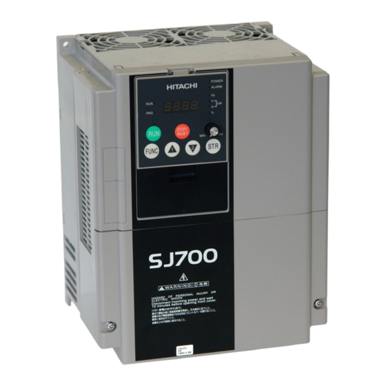
Page 20: Exterior Views And Names Of Parts
1.3 Exterior Views and Names of Parts The figure below shows an exterior view of the inverter (model SJ700-150LFF2/HFF2 to SJ700-220LFF2/HFF2). Front cover POWER lamp ALARM lamp Digital operator Spacer cover Terminal block cover For the wiring of the main circuit and control circuit terminals, open the terminal block cover. For mounting optional circuit boards, open the front cover. -
Page 21: Chapter 2 Installation And Wiring
Chapter 2 Installation and Wiring This chapter describes how to install the inverter and the wiring of main circuit and control signal terminals with typical examples of wiring. Installation ························································ 2 - 1 Wiring ······························································· 2 - 5... -
Page 23: Installation
2.1 Installation - Install the inverter on a non-flammable surface, e.g., metal. Otherwise, you run the risk of fire. - Do not place flammable materials near the installed inverter. Otherwise, you run the risk of fire. - When carrying the inverter, do not hold its top cover. Otherwise, you run the risk of injury by dropping the inverter. -
Page 24: Precautions For Installation
Chapter 2 Installation and Wiring 2.1.1 Precautions for installation (1) Transportation The inverter uses plastic parts. When carrying the inverter, handle it carefully to prevent damage to the parts. Do not carry the inverter by holding the front or terminal block cover. Doing so may cause the inverter to fall. - Page 25 (6) Installation method and position Install the inverter vertically and securely with screws or bolts on a surface that is free from vibrations and that can bear the inverter weight. If the inverter is not installed vertically, its cooling performance may be degraded and tripping or inverter damage may result.
-
Page 26: Backing Plate
Chapter 2 Installation and Wiring 2.1.2 Backing plate (1) For models with 22 kW or less capacity On the backing plate, cut the joints around each section to be cut off with cutting pliers or a cutter, remove them, and then perform the wiring. (2) For the models with 30 kW or less capacity 1) For wiring without using conduits Cut an X in each rubber bushing of the backing plate with cutting pliers or a cutter, and then perform... -
Page 27: Wiring
- Do not input single-phase power into the inverter. Otherwise, you run the risk of fire. - Do not connect AC power supply to any of the output terminals (U, V, and W). Otherwise, you run the risk of injury or fire. -
Page 28: Terminal Connection Diagram And Explanation Of Terminals And Switch Settings
-10 to +10 VDC (12 bits) 4 to 20 mA (12 bits) Analog monitor output (voltage output) 0 to 10 V (10 bits) Analog monitor output (current output) 4 to 20 mA (10 bits) HITACHI 停止/リセット 運転 STOP/RESET 機能 FUNC DC24V 10kΩ DC10V 10kΩ... - Page 29 If the source logic is selected, this terminal is used as a common contact input terminal. This common terminal supplies power to the interface power supply (P24), thermistor input (TH), and digital monitor (FM) terminals. If the sink logic is selected, this terminal is used as a common contact input terminal.
- Page 30 Jumper terminals P24 and PLC for the sink logic; jumper terminals CM1 and PLC for the sink logic. To use an external power supply to drive the contact inputs, remove the jumper, and connect the PLC terminal to the external interface circuit.
- Page 31 SW1 is set to OFF to disable the function.) Note: Before operating slide switch SW1, make sure that the input power supply is off. Note: Carefully note that improperly turning slide switch SW1 on or off will automatically change function assignments to the control terminals of the inverter.
- Page 32 Chapter 2 Installation and Wiring Setting of slide switch SW1 setting and function selection for intelligent input terminals [1] and [3] Intelligent input terminal [1] Setting of slide switch Terminal [1] function [C001] SW1 is OFF. Selectable arbitrarily (*4) Emergency stop Factory disabled setting...
- Page 33 Note: The Safe Stop function must be activated at least once a year for preventive maintenance purposes. Note: Before preventive maintenance, the machine must be turned off. If the power supply to the motor is not turned off during testing, the Safe Stop function will not operate. In such case, the inverter must be replaced.
- Page 34 Chapter 2 Installation and Wiring (Examples of wiring) - The examples of wiring below are intended to implement the Safe Stop function through safety input of the EMR signal by the method complying with EN954-1 Category 3. - The emergency stop circuit is monitored via an external safety relay (safety switching device). One safety relay (safety switching device) can be used for multiple inverters.
- Page 35 (Outline of operation) - S13: Emergency stop button to switch the inverter into safe stop mode and the motor into free-running status - S14: Start/stop button - Switches the inverter into safe stop mode by EMR signal input to a digital input terminal and sets the motor into free-running status.
-
Page 36: Wiring Of The Main Circuit
- This inverter does not support a single-phase power supply but supports only a three-phase power supply. If you need to use a single-phase power input, contact your supplier or local Hitachi Distributor. - Do not operate the inverter with an phase loss power input, or it may be damaged. - Page 37 3) DC reactor connection terminals (PD and P) - Use these terminals to connect the optional DC power factor reactor (DCL). As the factory setting, terminals P and PD are connected by a jumper. Remove this to connect the DCL. - The cable length between the inverter and DCL must be 5 m or less.
- Page 38 Chapter 2 Installation and Wiring (2) Layout of main circuit terminals The figures below show the terminal layout on the main circuit terminal block of the inverter. (L1) (L2) (L3) Ground terminal with jumper (shaded in the figure) to enable/disable the EMC filter function [Method of enabling/disabling the EMC filter function] Enabling the EMC filter...
- Page 39 Terminal layout (L1) (L2) (L3) (+1) Ground terminal with jumper (shaded in the figure) to enable/disable the EMC filter function [Method of enabling/disabling the EMC filter function] Enabling the EMC filter charge lump (L1) (L2) (L3) (+1) Jumper connecting Terminals PD and P When not using the DCL, do not remove the jumper from terminals PD and P.
- Page 40 Chapter 2 Installation and Wiring (L1) (L2) (L3) Jumper connecting Terminals PD and P When not using the DCL, do not remove the jumper from terminals PD and P. [Method of enabling/disabling the EMC filter function] Enabling the EMC filter Reference: Leakage current by inverter with model EMC filter enabled or disabled (reference data) The table below lists the reference currents that may leak from the inverter when the internal EMC filter is enabled or disabled.
- Page 41 (ACL-X-XX) Motor LCR filter connects a standard Hitachi 3-phase, 4-pole squirrel-cage motor. (Use breakers that comply with inverters.) temperature of the insulation is 75°C. applicable cable must be used for the power line. cable to connect the alarm output contact.
- Page 42 Connect a 3 A fuse in the control circuit power supply line. If the control circuit power supply (connected to R0 and T0) is turned on earlier than the main circuit power supply (connected to R, S, and T), ground fault is not checked at power-on.
- Page 43 Chapter 2 Installation and Wiring 2 - 21...
-
Page 44: Wiring Of The Control Circuit
7) When connecting a relay to an intelligent output terminal, also connect a surge-absorbing diode in parallel with the relay. 8) Do not connect analog power supply terminals H and L or interface power supply terminals P24 and CM1 to each other. -
Page 45: Wiring Of The Digital Operator
If you prepare the cable by yourself, the following product is recommended: HUTP5 PC 4P -X-X: Straight cable equipped with connector at both ends (made by Hitachi Cable, Ltd.) - The length of the connection cable must be 3 m or less. If a cable over 3 m is used, the inverter may malfunction. -
Page 46: Selection And Wiring Of Regenerative Braking Resistor (On 5.5 Kw To 22 Kw Models)
Chapter 2 Installation and Wiring 2.2.5 Selection and wiring of regenerative braking resistor (on 5.5 kW to 22 kW models) The SJ700-2 series inverter models with capacities of 5.5 to 22 kW have an internal regenerative braking circuit. Connecting an optional regenerative braking resistor to RB and P terminals increases the regenerative torque. -
Page 47: Chapter 3 Operation
This chapter describes typical methods of operating the inverter, how to operate the digital operator, and how to make a test run of the inverter. Chapter 3 Operation Operating Methods··········································· 3 - 1 How To Operate the Digital Operator ··············· 3 - 3 How To Make a Test Run ·································... -
Page 49: Operating Methods
3.1 Operating Methods - While power is supplied to the inverter, do not touch any terminal or internal part of the inverter, check signals, or connect or disconnect any wire or connector. Otherwise, you run the risk of electric shock or fire. - Page 50 This operating method allows you to operate the inverter via the input of operation signals from external devices (e.g., frequency-setting circuit and start switch) to control circuit terminals. The inverter starts operation when the input power supply is turned on and then an operation command signal (FW or RV) is turned on.
- Page 51 Chapter 3 Operation 3 - 3...
-
Page 52: How To Operate The Digital Operator
Chapter 3 Operation 3.2 How To Operate the Digital Operator (OPE-S) 3.2.1 Names and functions of components Monitor (4-digit LED display) RUN (operation) lamp PRG (program) lamp RUN key enable LED RUN key FUNC (function) key 1 (up) key Name POWER lamp Lights when the control circuit power is on. -
Page 53: Code Display System And Key Operations
3.2.2 Code display system and key operations This section describes typical examples of digital operator operation (in basic and full display modes) and an example of special digital operator operation in extended function mode U. The initial display on the monitor screen after power-on depends on the setting of function "b038". For details, see Section 4.2.81, "Initial-screen selection,"... - Page 54 Chapter 3 Operation (1) Example of operation in basic display mode ("b037" = "04" [factory setting]) - Only basic parameters can be displayed in basic display mode. (All parameters in monitor mode, four parameters in function mode, or 20 parameters in extended function mode) - Other parameters are not displayed.
- Page 55 Key operation and transition of the codes on display Pressing the key respectively scrolls up or down the code displayed in code display mode or increases or decreases the numerical data displayed in data display mode. Press the key until the desired code or numerical data is shown. To scroll codes or increase/decrease numerical data faster, press and hold the key.
- Page 56 Chapter 3 Operation (2) Example of operation in full display mode ("b037" = "00") All parameters can be displayed in full display mode. The display sequence of parameters matches their sequence shown in Chapter 8, "List of Data Settings." Key operation and transition of codes on display (in monitor or data on display (in monitor...
- Page 57 (3) Code/data display and key operation in extended function mode U The extended function mode U differs in operation from other extended function modes because the extended function mode U is used to register (or automatically record) other extended-function codes as user-specified U parameters.
- Page 58 Chapter 3 Operation (4) Procedure for directly specifying or selecting a code - You can specify or select a code or data by entering each digit of the code or data instead of scrolling codes or data in the monitor, function, or extended function mode. - The following shows an example of the procedure for changing the monitor mode code "d001"...
-
Page 59: How To Make A Test Run
(1) When entering operation and frequency-setting commands from the digital operator: (The operating procedure below is common to the standard and optional digital operators.) 3-phase power supply Default jumper position for sinking type inputs (Altanatively, CM1-PLC for souricing tiype) (Operating procedure) 1) Confirm that all wirings are correct. - Page 60 Chapter 3 Operation - Use the and/or reverse operation, and then press the (The display reverts to [F004].) 7) Set the monitor mode. - To monitor the output frequency, display the function code "d001", and then press the (The monitor shows the output frequency.) To monitor the operation direction, display the function code "d003", and then press the once.
- Page 61 3-phase power supply Operating box (OPE-4MJ2) (OPE-8MJ2) (Operating procedure) 1) Confirm that all wirings are correct. 2) Turn on the earth-leakage breaker (ELB) to supply power to the inverter. (The POWER lamp [red LED] of the digital operator goes on.) 3) Select the control circuit terminal block as the device to input frequency-setting commands by the frequency source setting function.
-
Page 62: Chapter 4 Explanation Of Functions
Chapter 4 Explanation of Functions This chapter describes the functions of the inverter. Monitor Mode ··················································· 4 - 1 Function Mode·················································· 4 - 7 Functions Available When the Feedback Option Board (SJ-FB) Is Mounted···················· 4 - 96 Communication Functions································ 4 - 113... -
Page 64: Monitor Mode
4.1 Monitor Mode 4.1.1 Output frequency monitoring When the output frequency monitoring function (d001) is selected, the inverter displays the output frequency. The inverter displays "0.00" when the frequency output is stopped. The Hz monitor lamp lights up while the inverter is displaying the output frequency. (Display) 0.00 to 99.99 in steps of 0.01 Hz 100.0 to 400.0 in steps of 0.1 Hz... -
Page 65: Intelligent Input Terminal Status (D005)
Chapter 4 Explanation of Functions 4.1.5 Intelligent input terminal status When the intelligent input terminal status function (d005) is selected, the inverter displays the states of the inputs to the intelligent input terminals. The internal CPU of the inverter checks each intelligent input for significance, and the inverter displays active inputs as those in the ON state. -
Page 66: Torque Command Monitoring (D009, P033, P034)
Chapter 4 Explanation of Functions 4.1.8 Actual-frequency monitoring The actual-frequency monitoring function is effective only when a motor equipped with an encoder is connected to the inverter and the feedback option board (SJ-FB) is mounted in the inverter. When the actual-frequency monitoring function (d008) is selected, the inverter displays the actual operating frequency of the motor (regardless of the motor control method (A044 or A244)). -
Page 67: Cumulative Power Monitoring (D015, B078, B079)
Chapter 4 Explanation of Functions 4.1.14 Cumulative power monitoring When the cumulative power monitoring function is selected, the inverter displays the cumulative value of electric power input to the inverter. You can also convert the value to be displayed to gain data by setting the cumulative input power display gain setting (b079). -
Page 68: Life-Check Monitoring (D022)
4.1.19 Life-check monitoring When the life-check monitoring function (d022) is selected, the inverter displays the operating life status of two inverter parts output from corresponding intelligent output terminals by using LED segments of the monitor. The two targets of life-check monitoring are: 1: Life of the capacitor on the main circuit board 2: Degradation of cooling fan speed Note 1: The inverter estimates the capacitor life every 10 minutes. -
Page 69: Programming Error Monitoring (D090)
Chapter 4 Explanation of Functions 4.1.27 Trip monitoring 1 to 6 When the trip monitoring function (d081 to d086) is selected, the inverter displays the trip history data. The last six protective trips the inverter made can be displayed. Select the trip monitoring 1 (d081) to display the data on the most recent trip. -
Page 70: Function Mode
Chapter 4 Explanation of Functions 4.2 Function Mode 4.2.1 Output frequency setting The output frequency setting function allows you to set the inverter output frequency. You can set the inverter output frequency with this function (F001) only when you have specified "02" for the frequency source setting (A001). -
Page 71: Run Command Source Setting (A002, C001 To C008, C019, F004)
4.2.4 Frequency source setting The frequency source setting function allows you to select the method to input the frequency-setting command. Motor rotation direction is inverted when -10 to 0V is given as frequency command to 02-L terminals. Item Function code Frequency source A001... -
Page 72: Stop Mode Selection (B091, F003, B003, B007, B088)
4.2.6 Stop mode selection The stop mode selection function allows you to select one of two methods of stopping the motor when a stop command is input from the digital operator or via the control circuit terminal block. One is to decelerate the motor according to the specified deceleration time and then stop it;... -
Page 73: Acceleration/Deceleration Time Setting (F002, F003, A004, P031, C001 To C008)
Chapter 4 Explanation of Functions 4.2.8 Acceleration/deceleration time setting - Specify a longer time for slower acceleration or deceleration; specify a shorter time for quicker acceleration or deceleration. - The time set with this function is the time to accelerate (or decelerate) the motor from 0 Hz to the maximum frequency (or vice versa). -
Page 74: Base Frequency Setting (A003, A081, A082)
4.2.9 Base frequency setting (1) Base frequency and motor voltage - With the base frequency setting and AVR voltage select functions, adjust the inverter outputs (frequency and voltage) to the motor ratings. - The base frequency is the nominal frequency of the motor. Set a base frequency that meets the motor specification. -
Page 75: External Analog Input Setting (O, O2, And Oi) (A005, A006, C001 To C008)
Chapter 4 Explanation of Functions 4.2.11 External analog input setting (O, OI, and O2) The inverter has the following three types of external analog input terminals: O-L terminal: 0 to 10 V OI-L terminal: 4 to 20 mA O2-L terminal: -10 to 10 V The table below lists the settings of the external analog input terminals. - Page 76 (Example 1 ) When the motor o peration is not r eversible Main frequenc command via the OI or O t erminal iliary frequenc command via the O2 te rminal Actual frequenc Forward operation command 4.2.12 Frequency operation function The frequency operation function allows you to use the result of an arithmetic operation on two frequency commands as the actual frequency command or PID feedback data.
-
Page 77: Frequency Addition Function (A145, A046, C001 To C008)
Chapter 4 Explanation of Functions 4.2.13 Frequency addition function The frequency addition function allows you to add or subtract the value specified as the frequency to be added (A145) to or from the frequency value of a selected frequency command. To use this function, assign function "50"... -
Page 78: External Analog Input (O/Oi/O2) Filter Setting (A016)
(2) Start/end frequency settings for the O2-L terminal Item Function code 02 start frequency A111 02 end frequency A112 02 start-frequency A113 rate 02 end-frequency A114 rate *1 The frequency rates correspond to the voltages (-10 to +10 V) of the external frequency command as follows: -10 to 0 V: -100% to 0% 0 to +10 V: 0% to 100%... -
Page 79: V/F Characteristic Curve Selection (A044, B100, B101)
Chapter 4 Explanation of Functions 4.2.17 V/F characteristic curve selection The V/F characteristic curve selection function allows you to set the output voltage/output frequency (V/f) characteristic. To switch the V/F characteristic curve selection among the 1st, 2nd, and 3rd settings, assign function "08" (SET) and "17" (SET3) to intelligent input terminals. - Page 80 (3) Free V/f characteristic setting The free V/f characteristic setting function allows you to set an arbitrary V/f characteristic by specifying the voltages and frequencies (b100 to b113) for the seven points on the V/f characteristic curve. The free V/f frequencies (1 to 7) set by this function must always be in the collating sequence of "1 ≤ 2 ≤ 3 ≤...
-
Page 81: Torque Boost Setting (A041, A042, A043, H003, H004)
Chapter 4 Explanation of Functions 4.2.18 Torque boost setting The torque boost setting function allows you to compensate for the voltage drop due to wiring and the primary resistance of the motor so as to improve the motor torque at low speeds. When you select automatic torque boost by the torque boost selection (A041/A241), adjust the settings of the motor capacity selection (H003/H203) and motor pole selection (H004/H204) - Page 82 (2) Automatic torque boost When automatic torque boost (data "01") is selected by the torque boost selection (A041/A241), the inverter automatically adjusts the output frequency and voltage according to the load on the motor. (During actual operation, the automatic torque boost is usually combined with the manual torque boost.) When you select the automatic torque boost, adjust the settings of the motor capacity selection (H003/H203) and motor pole selection (H004/H204) according to the motor to be driven.
- Page 83 Chapter 4 Explanation of Functions 4.2.19 DC braking (DB) setting The DC braking function allows you to apply DC braking to the motor according to the load on the motor. You can control DC braking in two ways: the external control through signal input to intelligent input terminals and the internal control to be performed automatically when the motor is started and stopped.
- Page 84 (2) External DC braking Assign function "07" (DB) to terminal function (C001 to C008). Turn the DB terminal on and off to control the direct braking, regardless of the setting of DC braking enable (A051). Adjust the braking force by adjusting the DC braking force setting (A054). When you set the DC braking wait time (A053), the inverter output will be shut off for the set period of delay, and the motor will run freely during the period.
- Page 85 Chapter 4 Explanation of Functions (3) Internal DC braking (A051: 01) You can apply DC braking to the motor even without entering braking signals via the DB terminal when the inverter starts and stops. To use the internal DC braking function, specify "01" for the DC braking enable (A051).
- Page 86 (4) Internal DC braking (triggered only when the output frequency reaches a set frequency) (A051: 02) You can also operate the internal DC braking function so that DC braking is applied to the motor when the inverter output frequency falls to the DC braking frequency setting (A052) or below. When the internal DC braking function is used in this mode, the external DC braking described in Item (2) and the internal DC braking described in Item (3) cannot be used.
-
Page 87: Frequency Upper Limit Setting (A061, A062)
Chapter 4 Explanation of Functions 4.2.20 Frequency upper limit setting The frequency upper limit setting function allows you to place upper and lower limits on the inverter output frequency. This function restricts the input of frequency commands that specify any frequencies outside the upper and lower limits. Always set the upper limit before setting the lower limit. -
Page 88: Jump Frequency Function (A063 To A068)
Chapter 4 Explanation of Functions 4.2.21 Jump frequency function The jump frequency function allows you to operate the inverter so that it avoids the resonant frequency of the machine driven by the same. Since the inverter avoids the motor operation with a constant output frequency within the specified range of the frequencies to jump when the jump frequency function is enabled, you cannot set any inverter output frequency within the specified range of the frequencies to... -
Page 89: Pid Function
4.2.23 PID function The PID function allows you to use the inverter for the process control on fluid flow, airflow, and pressure. To enable this function, specify "01 lenabled" or "02 inverted data output enabled" for function "A071". You can disable the PID function with an external signal during the PID operation. - Page 90 Chapter 4 Explanation of Functions (2) PID operation 1) P operation The proportional (P) operation stands for the operation in which the change in operation quantity is in proportion to the change in target value. Target value Operation quantity 2) I operation The integral (I) operation stands for the operation in which the operation quantity increases linearly over time.
- Page 91 When you specify the 02 RS485 communication for the PV source setting (A076), transfer data as described below. 1) When the ASCII mode is selected (C078 = 00) Use the 01 command for data transfer. To transfer feedback data, set the most-significant byte of frequency data to "1".
- Page 92 Chapter 4 Explanation of Functions (7) Output of inverted PID deviation If the inverter is under the normal PID control and the PID operation result is a negative value, the frequency command to the inverter will be limited to 0 Hz. However, when "02" (enabling the inverted output) is set for the PID Function Enable (A071), the PID operation result to be output to the inverter is inverted if the result is a negative value.
- Page 93 4.2.24 Two-stage acceleration/deceleration function (2CH) The two-stage acceleration/deceleration function allows you to change the acceleration or deceleration time while the inverter is accelerating or decelerating the motor. Select one of the following three methods of changing the acceleration or deceleration time: 1) Changing the time by the signal input to an intelligent input terminal 2) Automatically changing the time when the output frequency...
-
Page 94: Acceleration/Deceleration Curve Selection (A097, A098, A131, A132)
4.2.25 Acceleration/deceleration curve selection You can set different patterns of motor acceleration and deceleration according to the type of system to be driven by the inverter. Use functions "A097" and "A098" to select acceleration and deceleration patterns, respectively. You can individually set an acceleration pattern for acceleration and a deceleration pattern for deceleration. -
Page 95: Energy-Saver Operation (A085, A086)
Chapter 4 Explanation of Functions (2) Curve constant (swelling degree) Specify the swelling degree of the acceleration curve with reference to the following graphs: Output frequency (Hz) rget frequenc (100%) 96.9 82.4 17.6 Acceleration time (100%) to reach the set output frequency The acceleration or deceleration time may be shortened midway through the acceleration or deceleration according to the S-curve pattern. -
Page 96: Retry Or Trip After Instantaneous Power Failure
4.2.27 Retry or trip after instantaneous power failure (1) Retry (restart) after instantaneous power failure You can select tripping or retrying (restarting) the motor operation as the inverter operation to be performed at the occurrence of instantaneous power failure or undervoltage. If you specify a retry operation for the selection of restart mode (b001), the inverter will retry the motor operation for the number of times set as "b005"... - Page 97 *2 If a DC voltage (P-N) is supplied to control power supply terminals R0 and T0, the inverter may detect undervoltage and trip when the inverter power is turned off. If this cause a problem in your system, specify "00"...
- Page 98 Output of the alarms for instantaneous power failure and undervoltage in the stopped state Examples 5 to 7 show the alarm output operations with standard settings. Examples 8 to 10 show the alarm output operations with the settings to supply DC power (P-N) to control power supply terminals R0 and T0.
-
Page 99: Phase Loss Power Input Protection (B006)
Chapter 4 Explanation of Functions (3) Restarting methods - Restart with matching frequency The inverter detects the frequency and rotation direction based on the residual voltage in the motor, and then restarts the motor based on the detected frequency. - Restart with input frequency The inverter starts the output with the frequency specified for the start frequency selection (b030), searches for the point where the frequency and voltage are balanced while keeping the current at the restart current level (b028), and then restarts the motor. -
Page 100: Electronic Thermal Protection (B012, B013, B015, B016, C021 To C026, C061)
"b012", "b212", or "b312". The cooling-fan performance of a general-purpose motor lowers when the motor speed is low. So load (current) is decreased. The reduced-torque characteristic is designed to match the heat generation by Hitachi's general-purpose motors. Item Function code... - Page 101 Chapter 4 Explanation of Functions (b) Constant-torque characteristic Make this setting when driving a constant-torque motor with the inverter. Reduction scale X1.0 X0.9 X0.8 (c) Free setting of electronic thermal characteristic To protect the motor against overheating, you can set the electronic thermal characteristic freely according to the load on the motor.
-
Page 102: Overload Restriction/Overload Notice
Chapter 4 Explanation of Functions 4.2.30 Overload restriction/overload notice (1) Overload restriction function - The overload restriction function allows you to make the inverter monitor the motor current during acceleration or constant-speed operation and automatically reduce the output frequency according to the deceleration rate at overload restriction when the motor current reaches the overload restriction level. -
Page 103: Overcurrent Restraint (B027)
(2) Overload nitice function The overload notice function allows you to make the inverter output an overload notice signal before tripping because of overload. You can use this function effectively to prevent the machine (e.g., a conveyor)driven by the inverter from being overloaded and prevent the conveyor from being stopped by the overload protection of the inverter. - Page 104 Chapter 4 Explanation of Functions 4.2.32 Over voltage supression during deceleration - The over voltage supression function allows you to prevent the inverter from tripping because of the overvoltage that can be caused by the energy regenerated by the motor during deceleration. - You can enable or disable the function by setting the overvoltage suppression enable (b130).
-
Page 105: Start Frequency Setting (B082)
4.2.33 Start frequency setting The start frequency setting function allows you to specify the inverter output frequency that the inverter initially outputs when an operation command is input. Use this function mainly to adjust the start torque. If the start frequency (b082) is set too high, the inverter will start the motor with a full voltage, which will increase the start current. - Page 106 Chapter 4 Explanation of Functions 4.2.35 Carrier frequency setting The carrier frequency setting function (b083) allows you to change the carrier frequency of the PWM waveform output from the inverter. Increasing the carrier frequency can lower the metallic noise from the motor, but may increase the inverter noise and current leakage.
- Page 107 4.2.36 Automatic carrier frequency reduction - The automatic carrier frequency reduction function automatically reduces the carrier frequency according to the increase in output current. - To enable this function, specify "01" for automatic carrier frequency reduction selection (b089). Item Function code Automatic carrier b089 frequency reduction...
-
Page 108: Cooling-Fan Operation Setting (B092)
Chapter 4 Explanation of Functions 4.2.37 Dynamic braking (BRD) function The dynamic braking (BRD) function is provided in the SJ700-220LFF/HFF and other models that have the built-in BRD circuit. With this function, the energy regenerated by the motor is consumed by an external resistor (i.e., the energy is converted to heat). -
Page 109: Intelligent Input Terminal Setting (Set, Set3) (C001 To C008)
DC braking (external DC braking) function 2nd/3rd motor control function 2-stage acceleration/deceleration function Free-run stop function External trip function Unattended start protection function Commercial power supply switching function External analog input setting function 2nd/3rd motor control function Reset 3-wire input function PID function... -
Page 110: Multispeed Select Setting (Cf1 To Cf4 And Sf1 To Sf7)
Chapter 4 Explanation of Functions Function code Data F-TM: Forcible-terminal operation ATR: Permission of torque command input KHC: Cumulative power clearance SON: Servo On FOC: Forcing MI1: General-purpose input 1 MI2: General-purpose input 2 MI3: General-purpose input 3 MI4: General-purpose input 4 MI5: General-purpose input 5 MI6: General-purpose input 6 MI7: General-purpose input 7... - Page 111 (1) Binary operation mode Assign functions "02" (CF1) to "05" (CF4) individually to the terminal [1] to [8] functions (C001 to C008) to make multispeed s 0 to 15 available for selection. Specify the desired frequencies for speeds 1 to 15 by setting multispeeds 1 to 15 (A021 to A035). You can set speed 0 by using function "A020", "A220", "A320", or "F001"...
- Page 112 4.2.42 Jogging (JG) command setting The jogging command setting function allows you to set and finely tune the motor-stopping position. To use this function, assign function "06" (JG) to an intelligent input terminal. (1) Jog frequency setting Output f requency A038 Since the inverter operates the motor with a full voltage for the jogging operation, the inverter can easily trip during the latter.
-
Page 113: C001 Toc008)
Chapter 4 Explanation of Functions 4.2.43 2nd/3rd motor control function (SET and SET3) This motor control function allows you to switch the inverter settings to control three different types of motors. To use this function, assign function "08" (SET) and "17" (SET3) to two of the terminal [1] to [8] functions (C001 to C008). -
Page 114: C001 To C008
Chapter 4 Explanation of Functions 4.2.44 Software lock (SFT) function The software lock function allows you to specify whether to disable rewriting of the data set for functional items. Use this function to protect the data against accidental rewriting. You can select the functional items to be locked and the method of locking as described below. When using an intelligent input terminal for this function, assign function "15"... - Page 115 4.2.47 Free-run stop (FRS) function The free-run stop (FRS) function allows you to shut off the inverter output to let the motor start free-running. You can effectively use this function when stopping the motor with a mechanical brake (e.g., electromagnetic brake).
- Page 116 If the earth-leakage breaker (ELB) trips because of a ground fault, the commercial power will be disabled. Therefore, connect a backup power supply from the commercial power line circuit (ELBC) to your system if needed. Use weak-current type relays for FWY, RVY, and CSY.
- Page 117 Timing chart for switching from the inverter to the commercial power supply Inverter output Operation frequency 4.2.49 Reset (RS) function The reset function allows you to recover the inverter from a tripped state. To perform resetting, press the STOP/RESET key of the digital operator or turn the RS terminal off.
- Page 118 Chapter 4 Explanation of Functions (Example 1) Alarm (Example 3)If you select "01" (starting with matching frequency) as the restart mode after reset (C103), you can also make the inverter start the motor with matching frequency after the power reset. When "00" (starting with 0 Hz) is selected as the restart mode after reset (C103), the setting of the retry wait time before motor restart (b003) is ignored.
-
Page 119: Remote Control Function (Up And Dwn) (C101, C001 To C008)
4.2.50 Unattended start protection (USP) function The unattended start protection function allows you to make the inverter trip with error code "E13" displayed if the inverter power is turned on when an operation command has been turned on. You can recover the inverter from tripping by performing the reset operation or turning the operation command off. -
Page 120: 3-Wire Interface Operation Function (Sta, Stp, And F/R) (C001 To C008)
Chapter 4 Explanation of Functions 4.2.52 External trip (EXT) function The external trip function allows you to make the inverter trip according to the error (trip) signal generated by an external system. To use this function, assign function "12" (EXT) to one of the terminal [1] to [8] functions (C001 to C008). When the EXT terminal is turned on, the inverter trips with error code "E12"... -
Page 121: Control Gain Switching Function (Cas)
4.2.54 Control gain switching function (CAS) The control gain switching function allows you to set and switch between two types of gains and time constants for the speed control system (with proportional and integral compensations) when the V/F characteristic curve selection is the sensorless vector control, 0Hz-range sensorless vector control, or vector control with sensor. -
Page 122: Analog Command Holding Function (Ahd) (C001 To C008)
Chapter 4 Explanation of Functions The speed control normally incorporates the proportional integrated compensation (PI control), and the motor speed is controlled so that the difference between the frequency specified by the frequency command and the actual motor speed is zero. However, a specific operation mode (called drooping operation), in which one load is driven by multiple motors, sometimes requires the proportional control (P control). -
Page 123: Intelligent Output Terminal Setting (C021 To C026)
Chapter 4 Explanation of Functions 4.2.58 Intelligent output terminal setting You can assign the functions described below to the intelligent output terminals [11] to [15] (C021 to C025) and the alarm relay terminal (C026). The intelligent output terminals [11] to [15] are used for open-collector output, and the alarm relay terminal is used for relay output. - Page 124 Intelligent output terminals [11] to [15] have the following specifications: 15 CM2 … Inside the inverter Setting of C031 to C035 Power supply (a-contact) (b-contact) (2) Specifications of alarm relay terminal The alarm relay terminal uses a normally-closed (NC) contact that operates as described below.
- Page 125 4.2.60 Running signal (RUN) While the inverter is operating, it outputs the running (RUN) signal via an intelligent output terminal ([11] to [15]) or the alarm relay terminal. To use this signal function, assign function "00" (RUN) to one of the intelligent output terminals [11] to [15] (C021 to C025) and the alarm relay terminal (C026).
- Page 126 Chapter 4 Explanation of Functions (1) Signal output when the constant-speed frequency is reached (01: FA1) The inverter outputs the signal when the output frequency reaches the frequency specified by a frequency setting (F001, A020, A220, or A320) or multispeed setting (A021 to A035). Output frequency (2) Signal output when the set frequency is exceeded (02: FA2 or 24: FA4) The inverter outputs the signal when the output frequency exceeds the acceleration or deceleration...
- Page 127 4.2.62 Running time over and power-on time over signals (RNT and ONT) The inverter outputs the operation time over (RNT) signal or the plug-in time over (ONT) signal when the time specified as the run/power-on warning time (b034) is exceeded. Item Run/power-on warning time (1) Operation time over (RNT) signal...
-
Page 128: Alarm Code Output Function (Ac0 To Ac3) (C021 To C025, C062)
Chapter 4 Explanation of Functions 4.2.64 Over-torque signal (OTQ) The inverter outputs the over-torque signal when it detects that the estimated motor output torque exceeds the specified level. To enable this function, assign function "07" (OTQ: over-torque signal) to an intelligent output terminal. This function is effective only when the V/F characteristic curve selection selected with function "A044"... -
Page 129: Logical Output Signal Operation Function (Log1 To Log6)
Intelligent output terminals Factor code E20, E21 E50 to E79 Item Alarm code output 4.2.66 Logical output signal operation function (LOG1 to LOG6) The logical output signal operation function allows you to make the inverter internally perform a logical operation of output signals. - Page 130 Chapter 4 Explanation of Functions Item Function code Terminal function C021 to C025 C026 Alarm relay terminal function Logical output C142/C145/C148/ signal selection 1 C151/C154/C157 Logical output C143/C146/C149/ signal selection 2 C152/C155/C158 Logical output C144/C147/C150/ signal operator C153/C156/C159 selection 4.2.67 Capacitor life warning signal (WAC) The inverter checks the operating life of the capacitors on the internal circuit boards on the basis of the internal temperature and cumulative power-on time.
-
Page 131: Cooling-Fan Speed Drop Signal (Waf) (C021 To C026, B092 To D022)
4.2.69 Cooling-fan speed drop signal (WAF) The inverter outputs the cooling-fan speed drop (WAF) signal when it detects that the rotation speed of its internal cooling fan has fallen to 75% or less of the full speed. If "01" has been selected for the cooling fan control (b092), the inverter will not output the WAF signal, even when the cooling fan stops. -
Page 132: Low-Current Indication (Loc) Signal (C021 To C026, C038, C039)
- The inverter can recognize only the operation command that is input while the IRDY signal is output. - If the IRDY signal is not output, check whether the input power supply voltage (connected to the R, S, and T terminals) is within the range of specification. -
Page 133: Reverse Rotation Signal (Rvr) (C021 To C026)
Chapter 4 Explanation of Functions 4.2.75 Reverse rotation signal (RVR) The inverter continues to output the forward rotation (RVR) signal while it is driving the motor for reverse operation. The RVR signal is turned off while the inverter is driving the motor for forward operation or stopping the motor. -
Page 134: Window Comparators (Wco/Wcoi/Wco2)
4.2.77 Window comparators (WCO/WCOI/WCO2) (detection of terminal disconnection: ODc/OIDc/O2Dc) - The window comparator function outputs signals when the values of analog inputs O, OI, and O2 are within the maximum and minimum limits specified for the window comparator. You can monitor analog inputs with reference to arbitrary levels (to find input terminal disconnection and other errors). -
Page 135: Output Signal Delay/Hold Function (C130 To C141)
Chapter 4 Explanation of Functions 4.2.78 Output signal delay/hold function The output signal delay/hold function allows you to set on-delay and off-delay times for each output terminal. Since every output signal is turned on or off immediately when the relevant condition is satisfied, signal chattering may occur if signal outputs conflict with each other. -
Page 136: Fm Terminal (C027, B081)
Chapter 4 Explanation of Functions 4.2.81 FM terminal You can monitor the inverter output frequency and output current via the FM terminal on the control circuit terminal block. The FM terminal is a pulse output terminal. (1) FM siginal selection Select the signal to be output from the FM terminal among those shown below. -
Page 137: Am And Ami Terminals (C028, C029, C106, C108 To C110)
Chapter 4 Explanation of Functions 4.2.82 AM and AMI terminals You can monitor the inverter output frequency and output current via the AM and AMI terminals on the control circuit block. The AM terminal outputs an analog voltage signal (0 to 10 V). The AMI terminal outputs an analog current signal (4 to 20 mA). -
Page 138: Initialization Setting (B084, B085)
4.2.83 Initialization setting The initialization function allows you to initialize the adjusted settings on the inverter to restore the factory settings. You can also clear the trip history data alone. The settings of initialization are described below. The settings of "P100" to "P131", running-time data, and power-on time data cannot be cleared. Item Function code Initialization mode... - Page 139 Chapter 4 Explanation of Functions 4.2.84 Function code display restriction The function code display restriction function allows you to arbitrarily switch the display mode or the display content on the digital operator. Item Function code Function code b037 display restriction User parameters U001 to U012 (1) Function-specific display mode...
- Page 140 Display condition One of C001 to C008 = 05 and A019 = 00 One of C001 to C008 = 06 One of C001 to C008 = 07 One of C001 to C008 = 08 One of C001 to C008 = 08 and A041 = 01 One of C001 to C008 = 08 and A244 = 00 or One of C001 to C008 = 08 and A244 = 03 or One of C001 to C008 = 08 and A244 = 04...
-
Page 141: Initial-Screen Selection
Chapter 4 Explanation of Functions (4) Basic display mode The monitor displays basic parameters. (The monitor display is the factory setting.) The following table lists the parameters that can be displayed in basic display mode: Code displayed d001 to d104 Monitoring indication F001 Output frequency setting... -
Page 142: Automatic User-Parameter Setting (B039, U001 To U012)
4.2.86 Automatic user-parameter setting The automatic user-parameter setting function allows you to make the inverter automatically store the parameters you readjusted sequentially as user parameters "U001" to "U012". You can use the stored data as a readjustment history. To enable this function, select "01" (enabling automatic user-parameter setting) for the automatic user-parameter setting function enable (b039). - Page 143 Chapter 4 Explanation of Functions 4.2.89 Optimum accel/decel operation function The optimum accel/decel operation function eliminates the need for acceleration time and deceleration time settings for the motor operation by the inverter. Conventional inverters required you to adjust the acceleration and deceleration time according to the status of the load.
-
Page 144: Brake Control Function (B120 To B127, C001 To C008, C021, C025)
4.2.90 Brake control function The brake control function allows you to make the inverter control an external brake used for a lift or other machines. To enable this function, specify "01" (enabling the brake control function) for the Brake Control Enable (b120). This function operates as described below. - Page 145 Chapter 4 Explanation of Functions When using the brake control function, assign the following signal functions to intelligent input and intelligent output terminals as needed. (1) To input a signal indicating that the brake is released from the external brake to the inverter, assign the braking confirmation signal (44: BOK) to one of the terminal [1] to [8] functions (C001 to C008).
-
Page 146: Deceleration And Stopping At Power Failure
4.2.91 Deceleration and stopping at power failure (nonstop deceleration at instantaneous power failure) The nonstop deceleration at instantaneous power failure is the function making the inverter decelerate and stop the motor while maintaining the voltage below the overvoltage level when an instantaneous power failure occurs during the inverter operation. - Page 147 Chapter 4 Explanation of Functions <2> DC voltage constant control during nonstop operation at momentary power failure (b050 = 02: no restoration, b050 = 03: restoration to be done) - If momentary power failure occurs or the main circuit DC voltage drops during inverter operation, the inverter decelerates the motor while maintaining the main circuit DC voltage at the level specified as the target nonstop operation voltage at momentary power failure (0V-LAD stop level) (b052).
- Page 148 When "00" (Hitachi general-purpose motor data) is specified for the motor constant selection (H002/H202), the motor constants of Hitachi's general-purpose motors are set as defaults. When you drive a Hitachi's general-purpose motor with the inverter, you can usually obtain the desired motor characteristics without problems. (If you cannot obtain the desired characteristics, adjust the motor constant settings as described in Section 4.2.92 or...
- Page 149 Chapter 4 Explanation of Functions c) All brakes are released. d) During auto-tuning, insufficient torque may cause a problem in the load driven by the motor (for example, a lift may slide down). Therefore, remove the motor from the machine or other load, and perform auto-tuning with the motor alone.
-
Page 150: Online Auto-Tuning Function
2) Since the data for online tuning is calculated by the offline auto-tuning, perform the offline tuning at least once, even when the inverter is used to drive a Hitachi general-purpose motor. 3) The online auto-tuning operates for a maximum of 5 seconds after the motor has stopped. (DC excitation is executed once to tune constants R1 and R2. -
Page 151: Motor Constants Selection
→ Directly input the desired values for "H030" to "H034". When the offline auto-tuning has not been performed, the constants (Hitachi general-purpose motor constants) of the motors in the same capacity class as the inverter have been set for "H030/H230" to... - Page 152 Chapter 4 Explanation of Functions "H034/H234". 4 - 89...
-
Page 153: Sensorless Vector Control
4.2.96 Sensorless vector control The sensorless vector control function estimates and controls the motor speed and output torque on the basis of the inverter output voltage and output current and the motor constants set on the inverter. This function enables the inverter to accurately operate the motor with a high starting torque, even at a low frequency (0.3 Hz or more). -
Page 154: Sensorless Vector, 0 Hz Domain Control
4.2.97 Sensorless vector, 0 Hz domain control The 0Hz domain sensorless vector (SLV) control function incorporates Hitachi’s own torque control system and enables high-torque operation in the 0Hz range (0 to 3 Hz). This control function is best suited for driving a lifting machine, e.g., crane or hoist, that requires sufficient torque... -
Page 155: Torque Monitoring Function (A044, C027 To C029, H003, H004)
4.2.98 Torque monitoring function The torque monitoring function allows you to monitor the estimated motor output torque when the V/F characteristic curve selection is the sensorless vector control, 0Hz-range sensorless vector control, or vector control with sensor. To monitor the output torque on the digital operator, select code "d012"... -
Page 156: Torque Limitation Function (A044, B040 To B044, C001 To C008, C021 To C025)
4.2.100 Torque limitation function The torque limitation function allows you to limit the motor output torque when "03" (sensorless vector control), "04" (0Hz-range sensorless vector control), or "05" (vector control with sensor) is specified for the V/F characteristic curve selection (A044/A244). You can select one of the following four torque limitation modes with the torque limit selection (b040): 1) Quadrant-specific setting mode In this mode, individual torque limit values to be applied to four quadrants (i.e. -
Page 157: Reverse Run Protection Function (A044, B046)
When "00" (quadrant-specific setting mode) is specified for the torque limit selection (b040), the torque limits 1 to 4 apply as shown below. Reverse rotation (RV) When "01" (terminal-switching mode) is specified for the torque limit selection (b040), the torque limits 1 to 4 are set as shown in the example below. -
Page 158: Torque Lad Stop Function (A044, B040 To B045)
4.2.102 Torque LAD stop function The torque LAD stop function is effective when "03" (sensorless vector control), "04" (0Hz-range sensorless vector control), or "05" (vector control with sensor) is specified for the V/F characteristic curve selection (A044/A244). This function temporarily stops the frequency-based deceleration function (LAD) when the torque limitation function operates. -
Page 159: Easy Sequence Function (A017, P100 To P131)
4.2.104 Easy sequence function - You can create a user program with EzSQ (the programming software dedicated to the SJ700) on a personal computer, and download the program to your SJ700 series inverter. Thus, you can convert your inverter to a special machine on which user-defined functions are installed. -
Page 160: Functions Available When The Feedback Option Board (Sj-Fb) Is Mounted
4.3 Functions Available When the Feedback Option Board (SJ-FB) Is Mounted 4.3.1 Functions requiring the SJ-FB - The feedback option board (SJ-FB) is generally required in the following cases: <1> When "05" (V2: vector control with sensor) is specified for V/F characteristic curve selection, 1st motor(A044) <2>... - Page 161 Chapter 4 Explanation of Functions 4 - 98...
-
Page 162: Vector Control With Encoder Feedback
4.3.3 Vector control with encoder feedback - To use this control function, specify "05" (V2) for the V/F characteristic curve selection (A044). (You can specify the vector control with sensor only when the 1st motor control is selected.) - Before using this function, be sure to make optimum constant settings for the motor with reference to Section 4.2.95, "Motor constant selection."... -
Page 163: Torque Biasing Function
4.3.4 Torque biasing function The torque biasing function allows you to make the inverter bias the torque command generated during the operation in speed control mode. You can effectively use this function for inverter applications to a lift or other elevating machines. Item Function code Torque biasing mode... -
Page 164: Pulse Train Position Control Mode
(Control block diagram) ATR terminal Torque command input Speed limit Detected speed 4.3.6 Pulse train position control mode - To use this function, specify "05" (V2) for V/F characteristic curve selection, 1st motor (A044) and "01" (pulse train position control mode) for the control pulse setting (P012). - You can choose the input source of pulse train command pulse train mode setting (P013). - Page 165 *2 The following timing charts show the detailed operations in pulse train input mode. 1) MD0: 90°-phase-shift pulse train S AP S AN (Input of pulse train) S BP S BN (Input of pulse string) (パルス 列入力) 検出 パルス 数 Detected- pulse count 2) MD1: Forward/reverse operation command with pulse train...
-
Page 166: Electronic Gear Function
4.3.7 Electronic gear function The electronic gear function allows you to set a gain on the position command or position feedback data to adjust the ratio between the main motor and sub-motor speeds during the synchronous operation of the motors. Item Electronic gear set position selection... - Page 167 <Example of use: Synchronous operation> Master inverter M Main motor On the inverter (master inverter) for the main motor, specify either the speed control or pulse train position control mode. On the inverter (slave inverter) for the sub-motor, specify the pulse train position control mode. <Example of settings>...
-
Page 168: Motor Gear Ratio Setting Function
4.3.8 Motor gear ratio setting function The motor gear ratio setting function allows you to make the inverter effectively control a specific machine in which an encoder is installed at the opposite end of the motor. Specify the actual pulse count of the encoder as the encoder pulse-per-revolution (PPR) setting (P011). Specify the ratio of the motor speed to the encoder speed as the motor gear ratio (numerator "P028"... -
Page 169: Home Search Function
4.3.11 Home search function The home search function allows you to make the inverter locate the motor shaft at a specified position. You can use this function, for example, to stop a metal-cutting machine to replace the tool attached to the main spindle. When using the home search function, be sure to insert a reference point pulse signal between the EZP pulse and EZN pulse signals from the encoder. - Page 170 Note 1: Since the inverter positions the motor shaft within two turns while decelerating the motor, do not specify a high frequency as the home search speed. Otherwise, the inverter may trip during home search because of the overvoltage protection function. Note 2: For setting the home search stop position, the periphery of the motor shaft is divided into 4,096 sections to determine points No.
-
Page 171: Absolute Position Control Mode
4.3.12 Absolute position control mode - To use the absolute position control mode function, specify "05" (V2) for V/F characteristic curve selection, 1st motor (A044) and "02" (APR: absolute position control) for the control pulse setting (P012). - If "03" (high-resolution absolute position control) has been specified for the control pulse setting (P012), the quadruple number of pulses used for internal operations is applied to the control. -
Page 172: Operation In Absolute Position Control Mode
Multistage speed/position determination time Position setting monitor Position feedback monitor Reset mode selection 4.3.13 Operation in absolute position control mode Operation Output frequency Speed setting POK signal - In absolute position control mode, the inverter runs the motor until the machine reaches the target position according to the following settings, and then sets the machine into the position servo-lock state: <1>... - Page 173 Chapter 4 Explanation of Functions (Note that the internal position deviation counter is also cleared at the same time.) - In absolute position control mode, the ATR terminal is ineffective. (Torque control is disabled.) - In absolute position control mode, the STAT terminal is ineffective. (Pulse train position control is disabled.) - In absolute position control, the home search function is disabled.
-
Page 174: Multistage Position Switching Function (Cp1/Cp2/Cp3)
4.3.14 Multistage position switching function (CP1/CP2/CP3) - When functions "66" (CP1) to "68" (CP3) are assigned to terminal [1] function (C001) to terminal [8] function (C008), you can select a position setting from multistage positions 0 to 7. - Use multistage position settings 0 to 7 (P060 to P067) for the position settings. If no position settings are assigned to terminals, multistage position setting 0 (P060) is assumed. -
Page 175: Zero-Return Function
4.3.16 Zero-return function (ORG, ORL) - One of three types of zero-return operations can be selected by zero-return mode selection (P068). When a zero-return operation ends, the current position counter is cleared (to 0). - Use zero-return direction selection (P069) to select the direction of zero-return operation. - If zero-return operation is not performed, position control is performed based on the assumption that the motor position detected at power-on is the origin. -
Page 176: Forward/Reverse Drive Stop Function (Fot/Rot)
Note: In the case above, make sure that the power supply to the power terminals (R, S, and T) of the inverter power circuit or inverter output (U, V, and W) is disconnected from the motor. Performing teaching operation with the power supply and inverter output connected may result in personal injury or damage to equipment. -
Page 177: Servo-On Function
4.3.20 Servo-on function The servo-on function allows you to set the inverter in a speed- servo locking state with a signal input via an input terminal during operation. This function is effective when "05" (vector control with sensor) is specified as the V/F characteristic curve selection (A044). -
Page 178: Pulse Train Frequency Input
4.3.21 Pulse train frequency input The pulse train frequency input function allows you to use the pulse train input via the SAP or SAN terminal as a frequency command or PID feedback data in each control mode. (You can use this function in every control mode.) Specify the input frequency corresponding to the allowable maximum frequency as the pulse train frequency scale (P055). -
Page 179: Communication Functions
4.4 Communication Functions The inverter can engage in RS485 communications with an external control system that is connected to the TM2 terminal block (on the control circuit terminal block board) of the inverter. The SJ700 series inverter shares the ASCII communication protocol with the SJ300 and L300P series inverters. - Page 180 Connection As illustrated below, connect the inverters in parallel to the external control system, and connect the RP and SN terminals with a jumper on the inverter at the end of the network. (Similarly jumper the RP and SN terminals when only one inverter is connected to the external control system for RS485 communication.) Connecting the RP and SN terminals enables the terminating resistor in the control circuit terminal block board of the inverter, which suppresses signal reflections.
- Page 181 (3) Communication test mode Use the communication test mode to check the hardware of the RS485 communication train. (Procedure for communication test) 1) Remove all cables from the TM2 terminal block to perform a loopback test. 2) Make the following setting with the digital operator of the inverter: - Specify "02"...
-
Page 182: Communication In Ascii Mode
4.4.1 Communication in ASCII mode (1) Communication protocol The communication between the inverter and external control system is based on the following protocol: External control system Inverter (1): Frame that is sent from the external control system to the inverter (2): Frame that is sent from the inverter to the external control system The inverter sends frame (2) as a response always after receiving frame (1). - Page 183 The commands are described below. (i) 00 command: This command instructs the inverter to drive the motor (for forward or reverse rotation) or stop the motor. (To use this command, set "A002" to "03" [RS485].) - Transmission frame Frame format Station No.
- Page 184 (iii) 02, 12 command: This command turns the specified intelligent input terminals on or off. - Transmission frame Frame format Station No. Command Description Control code (Start of TeXt) Station number of control-target Station No. inverter Command Command to be transmitted Data Data to be transmitted Block check code...
- Page 185 Note 6: The table below lists the functions of the intelligent input terminals and corresponding hexadecimal data for 12 command. (For details, see the explanation of the intelligent input terminal functions.) Data (hexadecimal) Description 0000000000000001 0000000000000002 AHD: analog command holding 0000000000000004 CP1: multistage position settings 0000000000000008...
- Page 186 (iv) 03 command: This command reads all monitored data from the inverter. - Transmission frame Frame format Station No. Command Description Control code (Start of TeXt) Station number of control-target Station No. inverter Command Command to be transmitted Block check code Control code (Carriage Return) - Response frame Frame format...
- Page 187 (v) 04 command: This command reads the status of the inverter. - Transmission frame Frame format Station No. Command Description Control code (Start of TeXt) Station number of control-target Station No. inverter Command Command to be transmitted Block check code Control code (Carriage Return) - Response frame Frame format...
- Page 188 (vi) 05 command: This command reads the trip history data from the inverter. - Transmission frame Frame format Station No. Command Description Control code (Start of TeXt) Station number of control-target Station No. inverter Command Command to be transmitted Block check code Control code (Carriage Return) - Response frame Frame format...
- Page 189 (vii) 06 command: This command reads a specified setting item from the inverter. - Transmission frame Frame format Station No. Command Parameter Description Control code (Start of TeXt) Station number of control-target Station No. inverter Command Command to be transmitted Parameter Data parameter number Block check code...
- Page 190 (viii) 07 command: This command writes data to a specified setting item in the inverter. - Transmission frame Frame format Station No. Command Parameter Description Control code (Start of TeXt) Station number of control-target Station No. inverter Command Command to be transmitted Parameter Data parameter number Parameter data (decimal ASCII...
- Page 191 (x) 09 command: This command checks whether set data can be stored in the EEPROM in the inverter. - Transmission frame Frame format Station No. Command Description Control code (Start of TeXt) Station number of control-target Station No. inverter Command Command to be transmitted Block check code Control code (Carriage Return)
- Page 192 (xii) 0B command: This command recalculates the constants set in the inverter. This command must be issued when the base frequency or the setting of parameter "H***" has been changed for the RS485 communication. - Transmission frame Frame format Station No. Command Description Control code (Start of TeXt) Station number of control-target...
- Page 193 (2) Positive and negative responses (i) Positive response - Response frame Frame format Station No. Description Control code (Start of TeXt) Station number of control-target Station No. inverter Control code (acknowledgement) Block check code Control code (Carriage Return) (ii) Negative response - Response frame Frame format Station No.
- Page 194 (3) How to calculate the block check code (BCC) (Example) When using the 01 command (frequency-setting command) to set the inverter output frequency to 5 Hz (the station No. of the inverter is 01): Transmission fr ame configuration tation No. Comman The contents of "Station No."...
-
Page 195: Communication In Modbus-Rtu Mode
4.4.2 Communication in Modbus-RTU mode (1) Communication protocol The communication between the inverter (slave) and external control system (master) is based on the following protocol: External control system Inverter (1): Query frame that is sent from the external control system to the inverter (2): Response frame that is sent from the inverter to the external control system (3): Communication trip limit time (C077) If the inverter cannot complete the reception of a query from the master system (external control... - Page 196 The formats of the query and response frames are described below. Message configuration: Query (i) Slave address The slave address is a number 1 to 32 that is assigned to the inverter (slave) beforehand. (A query is received by the inverter having the same slave address as that specified in the query.) The query with the slave address set to "0"...
- Page 197 (iv) Error check code The Modbus-RTU protocol uses the cyclic redundancy check (CRC) as the error check method. The CRC code is the 16-bit data generated for a data block that has an arbitrary data length (in units of 8 bits). A generative polynomial for CRC-16 (X Example of CRC-16 calculation operation...
- Page 198 Message configuration: Response (i) Time required for communication After the inverter receives a query, the inverter waits for the sum of the silent interval (corresponding to the transmission of 3.5 characters) and the communication wait time (C078) before sending a response.
- Page 199 (4) Explanation of function codes (i) Reading the coil status [01h] This function reads the coil status (on or off). (Example) When reading the status of the intelligent input terminals [1] to [6] of the inverter at slave address "8": Assume that the intelligent input terminals are in the status as shown below.
- Page 200 (ii) Reading registers [03h] This function reads a specified number of registers beginning at a specified register address. (Example) When reading the trip history data from the inverter at slave address "5": Assume that the conditions of the past three trips are as follows: SJ700 command Register number Trip factor (upper digit)
- Page 201 (iii) Writing data to a specified coil [05h] This function writes data to a specified coil The following table shows the updating of the coil status. Updating data (upper digit) Updating data (lower digit) (Example) When sending an operation command to the inverter at slave address "10": To start the inverter operation, "03"...
- Page 202 (v) Performing a loopback test [08h] The loopback test function is used to check the communication between the external control system (master) and the inverter (slave). (Example) When performing a loopback test with the inverter at slave address "1": Query Field name Slave address (*1) Function code...
- Page 203 (vii) Writing data to multiple registers [10h] This function writes data to sequential registers. (Example) When setting "3,000 Hz" as the Acceleration (1) time (F002) in the inverter at slave address "1": Since register "1103h" and "1104h" to store the Acceleration (1) time (F002) have a data resolution of 0.01 seconds, specify "300000"...
- Page 204 (5) Enter command (storing the updates of register data) Neither the command (06h) to write data to a register nor the command (10h) to write data to multiple registers can store the updates they made in the internal memory of the inverter. Turning the inverter power off without storing the updates deletes them and restores the original register settings.
- Page 205 (6) List of registers The "R/W" column of the list indicates whether the coils and registers are read-only or readable and writable. "R" indicates a read-only coil or register. "R/W" indicates a readable and writable coil or register. (i) List of coils Coil No.
- Page 206 Coil No. Item 0035h LOG2 (logical operation result 2) 0036h LOG3 (logical operation result 3) 0037h LOG4 (logical operation result 4) 0038h LOG5 (logical operation result 5) 0039h LOG6 (logical operation result 6) 003Ah WAC (capacitor life warning) 003Bh WAF (cooling-fan speed drop) 003Ch FR (starting contact signal) 003Dh...
- Page 207 (ii) List of registers (frequency settings and trip monitoring) Register Function name 0001h Frequency source setting 0002h 0003h Inverter status A 0004h Inverter status B 0005h Inverter status C 0006h PID feedback 0007h (Reserved) 0010h 0011h Trip Counter 0012h Trip monitoring 1 (factor) 0013h Trip monitoring 1 (inverter status) 0014h Trip monitoring 1 (frequency) (high) 0015h Trip monitoring 1 (frequency (low)
- Page 208 Register Function name 003Ah Trip monitoring 5 (factor) 003Bh Trip monitoring 5 (inverter status) 003Ch Trip monitoring 5 (frequency) (high) 003Dh Trip monitoring 5 (frequency (low) 003Eh Trip monitoring 5 (current) 003Fh Trip monitoring 5 (voltage) 0040h Trip monitoring 5 (running time) (high) 0041h Trip monitoring 5 (running time) (low) 0042h...
- Page 209 List of inverter trip factors Upper part of trip factor code (indicating the factor) Name No trip factor Overcurrent protection during constant- speed operation Overcurrent protection during deceleration Overcurrent protection during acceleration Overcurrent protection during stopping Overload protection Braking resistor overload protection Overvoltage protection EEPROM error Undervoltage protection...
- Page 210 (iii) List of registers (monitoring) Register Function name 1001h Output frequency monitoring 1002h 1003h Output current monitoring 1004h Rotation direction minitoring 1005h Process variable (PV), PID feedback monitoring 1006h 1007h Intelligent input terminal status Intelligent output terminal 1008h status 1009h Scaled output frequency monitoring 100Ah...
- Page 211 (v) List of registers (function modes) Register Function name 1201h Frequency source setting Run command source 1202h setting 1203h Base frequency setting 1204h Maximum frequency setting 1205h [AT] selection 1206h [O2] selection 1207h to (Reserved) 120Ah 120Bh [O]-[L] input active range start frequency 120Ch 120Dh...
- Page 212 Register Function name 1236h (Reserved) 1237h (Reserved) 1238h Jog frequency setting 1239h Jog stop mode 123Ah (Reserved) Torque boost method 123Bh selection 123Ch Manual torque boost value Manual torque boost 123Dh frequency adjustment V/F characteristic curve 123Eh selection, 1st motor 123Fh V/f gain setting Voltage compensation gain...
- Page 213 Register Function name 125Fh PID Function Enable 1260h PID proportional gain 1261h PID integral time constant 1262h PID derivative gain 1263h PV scale conversion 1264h PV source setting 1265h Reverse PID 1266h PID output limiter 1267h PID feed forward selection 1268h (Reserved) 1269h...
- Page 214 Chapter 4 Explanation of Functions selection 1 via O), 3 (input via OI), 4 (external communication), 5 (option 1), 6 (option 2), 7 (pulse train frequency input) 4 - 151...
- Page 215 Register Function name Operation-target frequency 12B0h selection 2 12B1h Operator selection 12B2h (Reserved) 12B3h Frequency to be added 12B4h Sign of the frequency to be 12B5h added 12B6h to (Reserved) 12B8h EL-S-curve 12B9h acceleration/deceleration ratio 1 EL-S-curve 12BAh acceleration/deceleration ratio 2 EL-S-curve 12BBh deceleration/deceleration ratio 1...
- Page 216 Register Function name 1301h Selection of restart mode Allowable under-voltage power 1302h failure time Retry wait time before motor 1303h restart Instantaneous power 1304h failure/under-voltage trip alarm enable Number of restarts on power 1305h failure/under-voltage trip events 1306h Phase loss detection enable 1307h Restart frequency threshold 1308h...
- Page 217 Register Function name 1326h Reduced voltage start selection 1327h Function code display restriction 1328h Initial-screen selection Automatic user-parameter 1329h setting function enable 132Ah Torque limit selection Torque limit (1) (forward-driving 132Bh in 4-quadrant mode) Torque limit (2) (reverse- 132Ch regenerating in 4-quadrant mode) Torque limit (3) (reverse-driving 132Dh...
- Page 218 Cumulative input power display 1352h gain setting Register Function name 1354h (Reserved) 1355h Start frequency adjustment 1356h Carrier frequency setting Initialization mode (parameters 1357h or trip history) 1358h Country code for initialization Frequency scaling conversion 1359h factor 135Ah STOP key enable 135Bh Restart mode after FRS 135Ch...
- Page 219 Chapter 4 Explanation of Functions 4 - 156...
- Page 220 Register Function name 1401h Terminal [1] function 1402h Terminal [2] function 1403h Terminal [3] function 1404h Terminal [4] function 1405h Terminal [5] function 1406h Terminal [6] function 1407h Terminal [7] function 1408h Terminal [8] function 1409h (Reserved) 140Ah (Reserved) 140Bh Terminal [1] active state 140Ch Terminal [2] active state...
- Page 221 Register Function name 1415h Terminal [11] function 1416h Terminal [12] function 1417h Terminal [13] function 1418h Terminal [14] function 1419h Terminal [15] function 141Ah Alarm relay terminal function 141Bh [FM] siginal selection 141Ch [AM] siginal selection 141Dh [AMI] siginal selection Digital current monitor 141Eh reference value...
- Page 222 Register Function name 142Ah Frequency arrival setting for accel. 142Bh 142Ch Frequency arrival setting for decel. 142Dh 142Eh PID deviation level setting 142Fh Frequency arrival setting for acceleration (2) 1430h 1431h Frequency arrival setting for deceleration (2) 1432h 1433h to (Reserved) 1437h 1438h Maximum PID feedback data...
- Page 223 Register Function name 1470h (Reserved) 1471h AM bias adjustment 1472h AMI bias adjustment 1473h Overload setting (2) 1474h to (Reserved) 147Ch 147Dh [O] input zero calibration 147Eh [OI] input zero calibration 147Fh [O2] input zero calibration 1480h to (Reserved) 1485h 1486h Output 11 on-delay time 1487h...
- Page 224 Chapter 4 Explanation of Functions Function code R/W Monitoring and setting items Data resolution 0 (disabling auto-tuning), 1 (auto-tuning without H001 rotation), 2 (auto-tuning with rotation) 0 (Hitachi standard data), 1 (auto-tuned data), 2 H002 (auto-tuned data [with online auto-tuning function]) H003 R/W (*1)
- Page 225 Register Function name Operation mode on expansion card 1601h 1 error Operation mode on expansion card 1602h 2 error 1603h to (Reserved) 160Ah Encoder pulse-per-revolution (PPR) 160Bh setting 160Ch Control pulse setting 160Dh Pulse train mode setting 160Eh Home search stop position setting 160Fh Home search speed setting 1610h...
- Page 226 Register Function name 1633h Motor poles setting for RPM 1634h to (Reserved) 1638h 1639h Pulse train frequency scale Time constant of pulse train frequency 163Ah filter 163Bh Pulse train frequency bias 163Ch Pulse train frequency limit 163Dh (Reserved) 163Eh Multistage position setting 0 163Fh 1640h Multistage position setting 1...
- Page 227 Register Function name 1681h Easy sequence user parameter U (27) 1682h Easy sequence user parameter U (28) 1683h Easy sequence user parameter U (29) 1684h Easy sequence user parameter U (30) 1685h Easy sequence user parameter U (31) 1686h to (Reserved) 2102h *1 The following table lists the code data for parameter "H003"...
- Page 228 (vi) List of registers (2nd control settings) Register Function name 2103h Acceleration (1) time setting, 2nd motor 2104h 2105h Deceleration time, 2nd motor 2106h 2107h to (Reserved) 2202h (vii) List of registers (function modes for the 2nd control settings) Register Function name Base frequency setting, 2nd 2203h...
- Page 229 0 (reduced-torque characteristic), 1 (constant- b213 torque characteristic), 2 (free setting) Inaccessible 0 (Hitachi standard data), 1 (auto-tuned data), 2 H202 (auto-tuned data [with online auto-tuning function]) H203 R/W (*1) 0 (2 poles), 1 (4 poles), 2 (6 poles), 3 (8 poles), 4...
- Page 230 (viii) List of registers (3rd control settings) Register Function name 3103h Acceleration (1) time setting, 3rd motor 3104h 3105h Deceleration (1) time setting, 3rd motor 3106h 3107h to (Reserved) 3202h (ix) List of registers (3rd control setting) Register Function name Base frequency setting, 3rd 3203h motor...
-
Page 231: Chapter 5 Error Codes
This chapter describes the error codes of the inverter, error indications by the functions, and troubleshooting methods. Chapter 5 Error Codes Error Codes and Troubleshooting ···················· 5 - 1 Warning Codes················································· 5 - 10... -
Page 233: Error Codes And Troubleshooting
5.1 Error Codes and Troubleshooting 5.1.1 Error Codes Name Description If the motor is constrained or suddenly accelerated or decelerated, a high current will flow in the inverter and the inverter may fail. To avoid this problem, the inverter shuts off its output and displays the error code deceleration shown on the right when it... - Page 234 (Lower the input voltage, suppress the power voltage fluctuation, or connect an AC reactor OV.SRC between the power supply and the inverter input.) Check whether the power supply voltage has dropped. Check the MCB and magnetic contactors for poor Inst.P-F...
- Page 235 GA.COM Check whether the communication cable has been disconnected. Check for the phase loss power input. (Check the power supply input wiring.) Check the MCB and magnetic contactors for PH.fail poor contacts. (Replace the MCB and magnetic contactors.) Check for the noise sources located near the inverter.
- Page 236 Check whether the option board is mounted correctly. OP2-0 Check whether the option board is used correctly. OP2-9 Check whether the power supply voltage has fallen. Check the MCB and magnetic contactors for poor contacts. UV.WAIT Check whether the voltage across the P and N terminals is normal.
-
Page 237: Option Boards Error Codes
5.1.2 Option boards error codes When an option board is mounted in the optional port 1 (located near the operator connector), the error code display format is "E6*. " (on the digital operator) or "OP1-*" (on the remote operator). When it is mounted in the optional port 2 (located near the control circuit terminal block), the error code display format is "E7*. - Page 238 Chapter 5 Error Codes 2) Error indications by protective functions with the digital option board (SJ-DG) mounted Name If timeout occurs during the communication between the inverter and digital option board, the SJ-DG error inverter will shut off its output and display the error code shown on the right.
- Page 239 3) Error indications by protective functions with the DeviceNet option board (SJ-DN) mounted Name Description If the disconnection due to the Bus-Off signal or timeout occurs during the DeviceNet operation using DeviceNet commands, communicatio the inverter will shut off its output and n error display the error code shown on the right.
- Page 240 Chapter 5 Error Codes 4) Error indications by protective functions with the easy sequence function used Name - The inverter will display the error code shown on the right if an invalid instruction is found in a downloaded program. (*1) Invalid instruction - The inverter will display the error code if the PRG terminal is turned on when no program has been...
-
Page 241: Trip Conditions Monitoring
5.1.3 Trip conditions monitoring These digits indicate a trip factor. See Section 5.1.1. 2) Output frequency (Hz) at tripping 3) Output current (A) at tripping 4) DC voltage (V) across P and N terminals at tripping 5) Accumulated time (h) for which the inverter has been running before tripping 6) Accumulated time for which the inverter power has been on before tripping... -
Page 242: Warning Codes
Chapter 5 Error Codes 5.2 Warning Codes The following table lists the warning codes and the contents of parameter readjustments: Warning code 001/ 201 Frequency upper limit setting (A061/A261) 002/ 202 Frequency lower limit setting (A062/A262) 004/ 204/ 304 Base frequency setting (A003/A203/A303) (*1) Output frequency setting (F001), multispeed 0 005/ 205/ 305 (A202/A220/A320) (*2) -
Page 243: Chapter 6 Maintenance And Inspection
Chapter 6 Maintenance and Inspection This chapter describes the precautions and procedures for the maintenance and inspection of the inverter. Precautions for Maintenance and Inspection ... 6-1 Daily and Periodic Inspections ... 6-2 Ground Resistance Test with a Megger ... 6-3 Withstand Voltage Test... -
Page 245: Precautions For Maintenance And Inspection
6.1 Precautions for Maintenance and Inspection - Before inspecting the inverter, be sure to turn off the power supply and wait for 10 minutes or more. Otherwise, you run the risk of electric shock. (Before inspection, confirm that the Charge lamp on the inverter is off and the DC voltage between terminals P and N is 45 V or less.) -
Page 246: Daily And Periodic Inspections
General Environment Check the ambient temperature, humidity, and dust. Whole inverter Check for abnormal vibrations and noise. Power supply Check that the main circuit voltage voltage is normal. Main General check (1) Check the ground resistance circuit between the main circuit and ground terminals with a megger. -
Page 247: Ground Resistance Test With A Megger
Note that only inverter models with a capacity of less than 22 kW have the RB terminal. Power supply Do not connect power supply cables to the inverter. 500 VDC megger 6.4 Withstand Voltage Test Do not carry out a withstand voltage test for the inverter. -
Page 248: Method Of Checking The Inverter And Converter Circuits
You can check the quality of the inverter and converter circuits by using a tester. (Preparation) 1) Remove the external power supply cables from terminals R, T, and T, the motor cables from terminals U, V, and W, and the regenerative braking resistor cables from terminals P and RB. -
Page 249: Dc-Bus Capacitor Life Curve
6.6 DC-Bus Capacitor Life Curve Ambient temperature (ºC) Note 1: The ambient temperature indicates the temperature measured at a position about 5 cm distant from the bottom center of the inverter body. If the inverter is mounted in an enclosure, the ambient temperature is the temperature within the enclosure. -
Page 250: Methods Of Measuring The Input/Output Voltages, Current, And Power
Chapter 6 Maintenance and Inspection 6.8 Methods of Measuring the Input/Output Voltages, Current, and Power This section describes the measuring instruments generally used to measure the input and output voltages, output current, and output power of the inverter. Power supply Measurement Measuring point item... -
Page 251: Chapter 7 Specifications
This chapter describes the specifications and external dimensions of the inverter. Chapter 7 Specifications Specifications ... 7-1 External dimensions ... 7-4... - Page 253 7.1 Specifications (1) Specifications of the 200 V class model Model name (type name) SJ700-XXXLFF,LFU Max. applicable motor capacity (4-pole) (kW) Rated capacity 200V (kVA) 240V Rated input AC voltage Rated output voltage Rated output current (A) Regenerative braking Internal BRD circuit (external discharge resistor) Minimum connectable resistance (Ω) Approx.
- Page 254 2-stage acceleration/deceleration (2CH), free-run stop (FRS), external trip (EXT), unattended start protection (USP), commercial power supply switching (CS), software lock (SFT), analog input switching (AT), 3rd motor control (SET3), reset (RS), starting by 3-wire input (STA), stopping by 3-wire input (STP),...
- Page 255 (3) Common specifications of 200 V class and 400 V class models (continued) Model name (type name) SJ700-XXXXXFF.FEFFUF Ambient temperature, storage -10°C to +50°C (ambient), -20°C to +65°C (storage), 20% to 90% RH (no condensation allowed) temperature, humidity Vibration tolerance (See Note 1.) Installation Environment without corrosive gases and dust, at an altitude of 1,000 m or less...
-
Page 256: External Dimensions
Chapter 7 Specifications 7.2 External dimensions SJ700-055 to110LFF2/LFUF2 / HFF2/HFEF2/HFUF2 3 - Cable hole (33 x28) SJ700-150 to 220 LFF2/LFUF2 / HFF2/HFEF2/HFUF2 3 - Cable hole (42 x 42.5) 7 - 4... - Page 257 Chapter 7 Specifications SJ700-300 LFF2/LFUF2 / HFF2/HFEF2/HFUF2 5 - Cable hole (φ25) SJ700-370-450 LFF2/LFUF2 / HFF2/HFEF2/HFUF2, 550 HFF2/HFEF2/HFUF2 5 - Cable hole (φ41) 7 - 5...
- Page 258 Chapter 7 Specifications SJ700-550 LFF2/LFUF2 5 - Cable hole (φ41) 7 - 6...
-
Page 259: Chapter 8 List Of Data Settings
Chapter 8 List of Data Settings This chapter lists the data settings for the various functions of the inverter. 8.1 Precautions for Data Setting ...8-1 8.2 Monitoring Mode...8-1 8.3 Function Mode ...8-2 8.4 Extended Function Mode ...8-3... -
Page 261: Precautions For Data Setting
8.1 Precautions for Data Setting The default display mode limits the screens (parameters) that can be displayed on the monitor. To enable the display of all parameters, specify "00" (full display) for the function code display restriction (b037). To enable the parameters to be changed while the inverter is operating, specify "10" for the software lock mode selection (b031). 8.2 Monitoring Mode With the default settings, the monitor always displays the data output according to the output frequency monitoring (d001) after power-on. -
Page 262: Function Mode
Chapter 8 List of Data Settings Code Function name d025 User monitor 0 d026 User monitor 1 d027 User monitor 2 d028 Pulse counter d029 Position setting monitor d030 Position feedback monitor d080 Trip Counter Trip monitoring 1 d081 Trip monitoring 2 d082 Trip monitoring 3 d083... -
Page 263: Extended Function Mode
8.4 Extended Function Mode Code Function name Frequency source setting 00 (keypad potentiometer) (*1), 01 (control circuit terminal block), 02 (digital A001 operator), 03 (RS485), 04 (option 1), 05 (option 2), 06 (pulse-string input), 07 (easy sequence), 10 (operation function result) Run command source setting 01 (control circuit terminal block), 02 (digital operator), 03 (RS485), 04 (option A002... - Page 264 Chapter 8 List of Data Settings Code Function name A041 Torque boost method selection 00 (manual torque boost), 01 (automatic torque boost) Torque boost method selection, A241 00 (manual torque boost), 01 (automatic torque boost) 2nd motor A042 Manual torque boost value 0.0 to 20.0 (%) Manual torque boost value, 2nd A242...
- Page 265 Code Function name A081 AVR function select 00 (always on), 01 (always off), 02 (off during deceleration) 200 V class: 200, 215, 220, 230, 240 (V) A082 AVR voltage select 400 V class: 380, 400, 415, 440, 460, 480 (V) A085 Operation mode selection 00 (normal operation), 01 (energy-saving operation), 02 (fuzzy operation)
- Page 266 Chapter 8 List of Data Settings Code Function name 00 (tripping), 01 (starting with 0 Hz), 02 (starting with matching frequency), 03 b001 Selection of restart mode (tripping after deceleration and stopping with matching frequency), 04 (restarting with active matching frequency) Allowable under-voltage power b002 0.3 to 25.0 (s)
- Page 267 Code Function name b034 Run/power-on warning time 0. to 9999. (0 to 99990), 1000 to 6553 (10000 to 655300) (hr) 00 (enabling both forward and reverse rotations), 01 (enabling b035 Rotational direction restriction only forward rotation), 02 (enabling only reverse rotation) 0 (minimum reduced voltage start time) to 255 (maximum b036 Reduced voltage start selection...
- Page 268 Chapter 8 List of Data Settings Code Function name Cumulative input power data b078 Clearance by setting "01" and pressing the STR key clearance Cumulative input power display b079 1. to 1000. gain setting b082 Start frequency adjustment 0.10 to 9.99 (Hz) b083 Carrier frequency setting 0.5 to 15.0 (kHz) (subject to derating)
- Page 269 Code Function name 01 (RV: Reverse RUN), 02 (CF1: Multispeed 1 setting), 03 (CF2: Multispeed 2 C001 Terminal [1] function (*2) setting), 04 (CF3: Multispeed 3 setting), 05 (CF4: Multispeed 4 setting), 06 (JG: Jogging), 07 (DB: external DC braking), 08 (SET: Set 2nd motor data), 09 (2CH: C002 Terminal [2] function 2-stage acceleration/deceleration), 11 (FRS: free-run stop), 12 (EXT: external trip),...
- Page 270 Chapter 8 List of Data Settings Code Function name C021 Terminal [11] function 00 (RUN: running), 01 (FA1: constant-speed reached), 02 (FA2: set frequency overreached), 03 (OL: overload notice advance signal (1)), 04 C022 Terminal [12] function (OD: output deviation for PID control), 05 (AL: alarm signal), 06 (FA3: set C023 Terminal [13] function frequency reached), 07 (OTQ: over-torque), 08 (IP: instantaneous power...
- Page 271 Code Function name Low-current indication signal 00 (output during acceleration/deceleration and constant-speed operation), C038 output mode selection 01 (output only during constant-speed operation) Low-current indication signal C039 0.0 to 2.00 x "rated current" (A) detection level 00 (output during acceleration/deceleration and constant-speed operation), C040 Overload signal output mode 01 (output only during constant-speed operation)
- Page 272 Chapter 8 List of Data Settings Code Function name C111 Overload setting (2) 0.0 to 2.00 x "rated current" (A) C121 [O] input zero calibration 0. to 9999., 1000 to 6553 (10000 to 65530) C122 [OI] input zero calibration 0. to 9999., 1000 to 6553 (10000 to 65530) C123 [O2] input zero calibration 0.
- Page 273 00 (disabling auto-tuning), 01 (auto-tuning without rotation), 02 (auto-tuning H001 Auto-tuning Setting with rotation) 00 (Hitachi standard data), 01 (auto-tuned data), H002 Motor data selection, 1st motor 02 (auto-tuned data [with online auto-tuning function]) 00 (Hitachi standard data), 01 (auto-tuned data),...
- Page 274 Chapter 8 List of Data Settings Code Function name H050 PI proportional gain for 1st motor 0.0 to 999.9, 1000. H250 PI proportional gain for 2nd motor 0.0 to 999.9, 1000. H051 PI integral gain for 1st motor 0.0 to 999.9, 1000. H251 PI integral gain for 2nd motor 0.0 to 999.9, 1000.
- Page 275 Code Function name Operation mode on expansion card P001 00 (tripping), 01 (continuing operation) 1 error Operation mode on expansion card P002 00 (tripping), 01 (continuing operation) 2 error Encoder pulse-per-revolution P011 128. to 9999., 1000 to 6553(10000 to 65535) (pulses) (PPR) setting P012 Control pulse setting...
- Page 276 Chapter 8 List of Data Settings Code Function name Position setting range reverse side to forward side P060 Multistage position setting 0 (upper 4 digits including “-“) Position setting range reverse side to forward side P061 Multistage position setting 1 (upper 4 digits including “-“) Position setting range reverse side to forward side P062...
- Page 277 Code Function name Easy sequence user parameter U P116 0. to 9999., 1000 to 6553 (10000 to 65535) (16) Easy sequence user parameter U P117 0. to 9999., 1000 to 6553 (10000 to 65535) (17) Easy sequence user parameter U P118 0.
- Page 278 Chapter 8 List of Data Settings Code Function name U001 User-selected function 1 no/d001 to P131 U002 User-selected function 2 no/d001 to P131 U003 User-selected function 3 no/d001 to P131 U004 User-selected function 4 no/d001 to P131 U005 User-selected function 5 no/d001 to P131 U006 User-selected function 6...
- Page 279 Upgrading from the SJ300 Series The SJ300 series inverter is upwardly compatible with the SJ700 series inverter. Therefore, you can: - mount the control circuit terminal block board of the SJ300 series in the SJ700 series without removing the connected cables, - copy the parameter settings from the SJ300 series into the SJ700 series, and - use the option boards mounted in the SJ300 series for the SJ700 series without removing the connected cables.
- Page 280 Appendix (2) Copying the parameter settings If you use an optional remote operator (SRW-OJ or SRW-OEX), you can copy (import) the parameter settings from the SJ300 series into the SJ700 series. Note, however, that you cannot copy the parameter settings from the SJ700 series to the SJ300 series because the SJ700 series has many new functions and additional parameters.
- Page 281 BRK ...4-81 capacitor life warning ...4-46 carrier frequency ...4-12 CAS ...4-58 CE ...2-19 CF1, CF2, CF3, CF4...4-47 CM1 ...2-7, 2-21 commercial power supply switching...4-52 communication function ...4-66, 4-105 communication line disconnection signal...4-66 constant-torque characteristic (electronic thermal)...4-38 constant-torque characteristic (VC)...4-17, 4-85 control circuit terminal ...2-7...
- Page 282 Index frequency addition ... 4-15 frequency arrival setting for accel..4-61 frequency arrival setting for decel... 4-61 frequency limit ... 4-25 frequency lower limit... 4-25 frequency matching ...4-33, 4-52, 4-54 frequency operation... 4-14 frequency reached signal ... 4-61 frequency scaling conversion factor ... 4-2 Frequency source setting ...
- Page 283 O ...2-7, 2-21 O2 ... 2-7, 2-21, 4-12 O2Dc...4-71 OD ...4-28, 4-29 Odc ...4-71 offline auto-tuning ...4-82 OHF ...4-68 OI ...2-7, 2-21 OIDc...4-71 OL, OL2 ...4-40 OLR ...4-39 online auto-tuning ...4-84 ONT ...4-64 OPE ... 3-3, 4-8, 4-51 operating methodsS...3-1 operation after option error ...4-77 operation frequency ...4-14 operation mode ...4-33...
- Page 284 Index Teaching ... 4-110 test run ... 3-10 thermistor ... 4-4, 4-70 THM... 4-38 3-wire input ... 4-56 TL ... 4-92 torque bias monitoring ... 4-3 torque biasing ... 4-101, 4-102 torque boost... 4-18, 4-19 torque command monitoring ... 4-3 torque control...