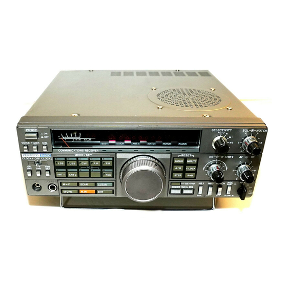
Kenwood R-5000 Instruction Manual
Communications receiver
Hide thumbs
Also See for R-5000:
- Service manual (128 pages) ,
- Instruction manual (35 pages) ,
- User handbook manual (35 pages)
Table of Contents
Advertisement
Quick Links
Advertisement
Table of Contents

Related Manuals for Kenwood R-5000


Summary of Contents for Kenwood R-5000
- Page 1 R-5000 COMMUNICATIONS RECEIVER INSTRUCTION MANUAL MULTIBAND- EMPFÄNGER BEDIENUNGSANLEITUNG RECEPTOR DE COMUNICACIONES MANUAL DE INSTRUCTIONES RECEPTEUR MANUEL D'INSTRUCTIONS RICEVITORE PER TELECOMUNICAZIONI ISTRUZIONI PER L'USO KENWOOD CORPORATION Scanned by Vincent Downloaded by ©PRINTED IN JAPAN B50-8237-10(W, W2)(T) RadioAmateur.EU 91/1211109876543...
-
Page 2: Safety
1. SAFETY Before applying power IMPORTANT! U.S.A. and Canada Units shipped to the U.S.A. and Canada are designed for operation on 120 volts AC only. These units are not equipped with an AC voltage selector switch and the Before plugging in this unit, make sure that the position discussion of such a switch that follows should be of the AC voltage selector conforms to your line (mains) disregarded. - Page 3 SAFETY INSTRUCTIONS 1. Read Instructions — All the safety and operating in- 12. Protective Attachment Plug — The optional DC opera- structions should be read before the appliance is oper- tion kit is supplied with an attachment plug having ated. overload protection.
- Page 4 EXAMPLE OF ANTENNA GROUNDING ACCORDING TO NATIONAL ELECTRICAL CODE INSTRUCTIONS CONTAINED IN ARTICLE 810 –"RADIO AND TELEVISION EQUIPMENT" a Use No. 10 AWG (5.3 mm 2 ) copper. No. 8 AWG (8.4 mm 2 ) alu- Mount antenna discharge unit as close as possible to where minuet, No.
- Page 5 Before operation Where to install the unit Safety precautions Do not place the unit near a heat producing equipment Never remove the case. If the internal parts are touched such as a radiator. Avoid direct sunlight. accidentally, a serious electric shock might occur. Do not store or use the unit in a dusty location or in a If a metal object, such as a hair pin or a needle, comes into moist atmosphere.
-
Page 6: Table Of Contents
Thank you for purchasing the new R-5000 Communications Receiver. Please read this Instruction Manual carefully before placing your receiver in service. This unit has been carefully engineered and manufactured to rigid quality standards, should give you satisfactory and dependable operation for many years. -
Page 7: Specifications And Accessories
Scanned by Vincent Downloaded by RadioAmateur.EU 2. SPECIFICATIONS AND ACCESSORIES 2-1. SPECIFICATIONS R-5000 Model Europe, U.K. and Australia West Germany other market U.S.A. version version version versions Specifications AM/USB/LSB/ Double conversion superheterodyne CW/FSK Circuitry Triple conversion superheterodyne 50 ohms ANT 1... -
Page 8: Accessories
2. *2: The optional DCK-2 DC Operation Kit is required for the DC Operation. 3. Circuit and ratings are subject to change without notice due to advancements in technology. 2-2. ACCESSORIES Unpack your R-5000 carefully and confirm that it is supplied with the following accessories. AC power cable (U.S.A. and Canada only) (E30-2071-05) 1 ea. -
Page 9: Installation And Connection
(A) AC operation sult to the radio When the R-5000 is to be operated from a fixed loca- 3. The clock and the timer function even if the POWER using normal household current you should con- switch is turned OFF. - Page 10 C. External speaker The R-5000 includes a built-in speaker. If you would like good audio quality. If you plan on using a speaker other to use an external speaker, such as the SP-430, it may be than the SP-430 it should be equipped with a miniature connected to the EXT SP jack on the rear of the radio.
- Page 11 The open-circuit voltage at pin 7 is about +4.8 VDC; the short circuit current is about 0.4 mA DC. 2. Connect the antenna to the R-5000 via the transmitter or transceiver antenna switching relay. If you are using a receive-only antenna, disconnect it from the R-5000 while transmitting.
-
Page 12: Operation
4. OPERATION 4-1. CONTROL FUNCTIONS 4-1-1. Front panel Scanned by Vincent Downloaded by RadioAmateur.EU Note: All segments on the Display Panel and Indi- cators are shown on for this explanation. ® Indicators POWER switch F.LOCK : Lights when the F.LOCK key is ON. Press to turn the power ON or OFF. - Page 13 known as the squelch threshold point. Now you will only hear output from the speaker when an incomming signal is present. For weak signal reception this control should be fully counterclockwise. Note: The squelch threshold position will vary from mode to mode, so you may have to readjust when you change mode.
- Page 14 AGC voltage and permit clear reception. been provided in the R-5000 are effective in most cases. If there is no "woodpecker" present, the switch should be AF gain control in the OFF position.
- Page 15 23 PHONES jack When pulsating noise, such as that caused by automobile ignitions is encountered, place the NB 1 switch ON. Output terminal for headphones. This switch will not help to eliminate atomospheric or line noises, only pulse type noise. 24 REC (Recording) jack Note: This terminal may be used for recording broadcasts on...
- Page 16 ® Frequency dis- Memory Channel play : Frequency of the VFO or the Me- number display : Memory Channel Number is dis- mory Channel is displayed. Fre- played. quency is expressed in 10 Hz Clock number steps (100 Hz for VHF band). display : When the POWER switch is Timer operation...
- Page 17 1 AC voltage selector switch (Except © REMOTE connector U.S.A. version) When the R-5000 is used with a transmitter or trans- to the "SAFETY" section on page 2. Refer ceiver, the REMOTE connector provides a mute pin to inhi- 4 DC power connector (Optional DCK-2 bit R-5000 audio output during transmission and an exter- DC Operation Kit is required.)
-
Page 18: Receive
Indication Beep tone 4-2-1. Microprocessor back-up battery 1 short beep When the following keys are pressed: The R-5000 has a rechargeable back-up battery which is ANT 1, ANT 2, A/ B, charged automatically while the AC power cable is con- F. - Page 19 The step size in which frequencies are changed by the Direct keyboard entry of the frequency is possible using TUNING knob can be changed by the MODE key and/or the Numeric Keypad on the R-5000. This allows rapid the STEP key. changes in frequency without the delays encountered Frequency Step when using other tuning methods.
- Page 20 800 Hz. 5. To receive AFSK (F2) signals, put the R-5000 in the FM 2. When an optional CW filter is installed the simplest mode. method to use is to adjust the TUNING knob for maxi- mum S-meter deflection.
-
Page 21: Memory
The VFO selected (A or B) before changing to the Me- 4-3-1. Memory entry mory Channel operation will be displayed. 1. With the R-5000 in the VFO mode, select the desired Example: operating frequency, mode and antenna number as de- When 14.175 MHz is stored in Memory Channel 23. - Page 22 1. During Memory Channel operation, press the VFO/M key to change to select VFO operation. 2. Press the M IN key once to initiate memory Scroll. The M.SCR indicator lights, and the memory Channel Fre- quency is displayed. (Although the displayed frequency Note: will change, actual reception will be at the previous fre- Contents of a Memory Channel can be transferred to the...
-
Page 23: Scan
5. To clear scanning, press the CLEAR key. 4-4-1. Memory scan Note: The R-5000 stops on a busy channel in the AM or FM The R-5000 microprocessor remembers the various scan modes. The radio will remain on the busy channel for ap- parameters that you have specified and will follow what- proximately 5 seconds and then start to scan again. - Page 24 2. Select the memory channel that you want to skip using When the AM or FM mode key is selected, the R-5000 will the Numeric Keypad, the TUNING knob, or the UP/ stop on a busy channel during scan operations. When an DOWN keys.
-
Page 25: Clock And Timer
HOUR switch resets the clock or timer. 4-5-2. Clock The R-5000 has two independent 24-hour clocks, CLOCK 1 and CLOCK 2. The clock times may be viewed with the POWER switch ON or OFF. Both methods are described below. - Page 26 4-5-3. Timer in ON. A. ON TIME set You can program the R-5000 to turn ON or OFF in synch- D. Checking the programmed times ronization with CLOCK 1. (The timer will not be controlled To check the programmed times, press the ON TIME or by the time set in CLOCK 2.)
-
Page 27: Maintenance
E. Turning external units ON or OFF You can use the R-5000's TIMER to turn external units such as tape recorders ON or OFF. Various pin connec- tions for timer states are shown below. Warning: 1. Never apply AC voltage to the REMOTE connector. -
Page 28: In Case Of Difficulty
5-4. IN CASE OF DIFFICULTY according to the following table. If the problem persists, The problems described in this table are failures caused in contact an authorized agent or service station. general by improper operation or connection of the re- ceiver, not by defective components. -
Page 29: Optional Accessories
MB-430 MOBILE MOUNT The Mobile Mount MB-430 allows easy installation and re- ■ HS-5 COMMUNICATIONS HEADPHONES moval of the R-5000. The MB-430 can either be suspend- (8 OHMS) ed from the dashboard or attached to the transmission Headphones designed for communications equipment. -
Page 30: References
7. REFERENCES 7-1. ENJOYING SW RECEPTION ENJOYING SW RECEPTION tic music from overseas broadcast stations or transmis- Every country in the world has broadcast stations, and sions from Amateur radio stations and various industrial, most countries have Amateur radio stations. The earth is marine, government, and military. - Page 31 Frequency Distribution in the Broadcast and Amateur Bands. The R-5000 receiver covers from 100 kHz to 30 MHz, to receive international broadcast and communication ser- vices. As shown in the Frequency Allocation Chart, broadcast and Amateur radio station frequencies are allocated in...
-
Page 32: Antenna And Grounding
7-2. ANTENNA AND GROUNDING • Inverted V Antenna This is a modified doublet antenna, designed to be in- 7-2-1. Antenna stalled on a single pole or support. The characteristics of The following describes various antenna types and their this antenna are almost the same as those of a doublet. installation. - Page 33 • Yagi Antenna 7-2-2. Grounding The Yagi antenna is best suited for reception in a specific Normally, the receiver will operate without being ground- band. This antenna features excellent directivity; it pro- ed. However, a good earth ground improves the efficiency vides high gain and minimizes interference when properly of antennas such as a long-wire.
- Page 36 Scanned by Vincent Downloaded by RadioAmateur.EU...