Table of Contents
Advertisement
Quick Links
CAUTION:
• This guide includes important information to use the product safely and to prevent
injury or property damage. Be sure to read this manual carefully and understand the
descriptions fully before using the product.
• Keep this guide with the product so that you can refer to it when needed.
• Transfer this guide with the product when transferring the product to another party.
LL009F
Tape Autoloader
User's Guide
6th Edition
Corporation
856-127974-200-A
Advertisement
Table of Contents

Related Manuals for NEC LL009F


Summary of Contents for NEC LL009F
- Page 1 LL009F Tape Autoloader User’s Guide 6th Edition CAUTION: • This guide includes important information to use the product safely and to prevent injury or property damage. Be sure to read this manual carefully and understand the descriptions fully before using the product.
-
Page 2: Safety Precautions
Safety Precautions To ensure safe use, carefully read and understand these Safety Precautions before using this unit. Handle this unit properly, as described in this manual, to prevent injury or property damage. Keep this guide at hand for immediate reference when needed. The following symbols are used in this guide to make it easy to understand how to operate the unit safely and correctly. - Page 3 Continuing to use the unit may cause fire. Note that data may be damaged if the unit is turned off during operation. Contact your local NEC sales representative or maintenance service company for repair. Take caution when mounting unit onto rack.
- Page 4 CAUTION Be careful when handling the LCD if broken. The unit contains an LCD. The LCD contains liquid which is harmful to the human body. In addition, the backlight of the LCD contains mercury. When touching the broken LCD, be careful not to touch the liquid inside the LCD. If the liquid leaking from the broken LCD enters the mouth, wash it out immediately and consult a doctor.
- Page 5 CAUTION Handling the power cord Observe the following cautions when handling the power cord. • Do not touch the plug with wet hands as this may cause electric shock. • When inserting the power cord into and removing it from the power outlet, be sure to hold the plug, not the cord.
- Page 6 CAUTION Maintenance precautions Note the following safety precautions when performing maintenance tasks. Failure to follow these precautions may result in serious injury. • Remove any electrically conductive objects being worn, such as a wristwatch or metal jewelry to help prevent electric shock. •...
- Page 7 CAUTION Cautions on installing the unit Observe the following cautions when installing the unit. • Do not install the unit in a location where it can come into direct contact with the outside air, which may include rain, mist, corrosive gases, or salt content. Doing so may cause electric shock, smoke, fire or damage to the unit.
-
Page 8: Warning Labels
Warning Labels The following warning labels have been attached to this unit. Customers and maintenance service personnel are urged to keep these warnings in the forefront of their minds when operating this unit. (Do not remove or soil these labels.) If any of these labels are missing, removed, soiled, or otherwise unreadable, contact your local maintenance service company. -
Page 9: Table Of Contents
Contents Safety Precautions ............................. 2 Warning Labels ............................8 Contents ..............................9 Figures .............................. 12 Tables ..............................13 PREFACE ..............................14 Remarks ..............................15 Disclaimer ..............................16 Restriction on use ............................. 16 Notice ................................ 17 FCC acceptance statement ......................17 CSA acceptance statement ...................... - Page 10 4.1.2 LED ............................36 4.1.3 Buttons ............................. 36 4.2 Panel Display ............................. 38 4.2.1 Menu screens .......................... 38 4.2.2 Display information........................39 4.3 Menu Tree ............................40 4.4 Main Menu ............................44 4.4.1 UNLOCK I/O STATION menu ....................44 4.4.2 UNLOCK MAGAZINE menu ....................44 4.4.3 COMMANDS menu ........................
- Page 11 6.1.3 Cleaning cartridges ....................... 108 6.2 Cartridge label ..........................109 6.3 Write Protection ..........................110 6.4 Handling Precautions ........................111 6.4.1 Use Precautions ........................111 6.4.2 General precautions......................111 6.4.3 Endurance ..........................112 6.4.4 Cartridge storage ........................112 Chapter 7 Maintenance ..........................113 7.1 Cleaning ............................
-
Page 12: Figures
Figures Figure 1-1 Components on Front of Autoloader ................19 Figure 1-2 Components on Rear of Autoloader ................20 Figure 1-3 Magazine Slot Numbers (1) ................... 21 Figure 1-4 Magazine Slot Numbers (2) ................... 21 Figure 2-1 Configuration of Rack Mount Kit Parts ................23 Figure 2-2 Illustration of Rack Bars .................... -
Page 13: Tables
Tables Table 2-1 Rack Mount Kit Configuration ..................23 Table 4-1 LCD Screen ........................36 Table 4-2 Operation Panel LEDs ..................... 36 Table 4-3 Operation Panel Buttons ....................36 Table 4-4 Autoloader Status Displayed In the Operation Panel ............. 39 Table 4-5 Submenus of COMMANDS Menu .................. -
Page 14: Preface
PREFACE This guide describes how to handle (mainly on hardware) the NEC LL009F Tape Autoloader (hereinafter referred to as the LL009F Autoloader, Autoloader, or Loader). For backup software commands and console messages, refer to the manual accompanying your backup software. -
Page 15: Remarks
(3) The information in this manual is subject to change without notice. (4) No part of this manual may be reproduced in any form without prior written consent from NEC. (5) Though the contents of this manual are thoroughly prepared, please contact the dealer you purchased if any question, mistakes or omissions are found. -
Page 16: Disclaimer
(3) NEC shall not be held liable for the damages caused by an earthquake, fire for which NEC is not responsible, improper act of a third party, other accidents, intentional or negligent act of a user, misuse, or operations under the abnormal conditions. -
Page 17: Notice
Notice Risk of product damage: The cables connected to the Autoloader must be shielded and grounded. Do not use non-specified cables. If this product is operated using unshielded or non-grounded cables, it may interfere with radio and/or television reception. Any modifications or alterations of this product that are made without express authorization will void the warranty. -
Page 18: Japanese Acceptance Statement
Japanese acceptance statement Description of symbols WEEE Disposing of your used NEC product In the European Union EU-wide legislation as implemented in each Member State requires that used electrical and electronic products carrying the mark (left) must be disposed of separately from normal household waste. -
Page 19: Chapter 1 General Information
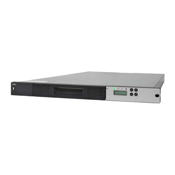
Chapter 1 General Information This chapter describes the main hardware components and the loader specifications. The LL009F Tape Autoloader is an auto cartridge management system that includes an LTO Ultrium drive. The Autoloader can hold up to nine cartridges. 1.1 Names and Functions of Components The locations of the Autoloader's various components are described below. -
Page 20: Rear Of Autoloader
1.1.2 Rear of Autoloader Figure 1-2 Components on Rear of Autoloader <3> <2> <1> <4> <5> <6> <1> Power switch <2> Power outlet <3> SAS connector <4> Exhaust aperture <5> Ethernet access point <6> Fastening screw for shipping - 20 -... -
Page 21: Magazine Slots
1.2 Magazine Slots The magazine includes five columns, and two cartridges can be inserted depth wise in each column. In total, nine cartridges can be inserted into the magazine. The first slot holds the cartridge that is used as the exchange cartridge. Caution: When loading cartridges into the magazine, do not insert a cartridge into the exchange slot. -
Page 22: Data Slots
1.2.1 Data slots These slots are used to store data cartridges. Magazine slots are assigned sequentially, starting from the number that has been set via the "Origin" setting in the operation panel. The number of data slots matches the number of user slots set via the operation panel. 1.2.2 I/O STATION slot This slot is used to insert cartridges into the Autoloader and to remove them. -
Page 23: Chapter 2 Installation
Chapter 2 Installation This chapter describes steps and caution points for installing the Autoloader in a rack. 2.1 Attach the Rack Mount Kit (1) Parts The rack mount kit includes the following parts. Figure 2-1 Configuration of Rack Mount Kit Parts <1>... -
Page 24: Figure 2-2 Illustration Of Rack Bars
(2) Caution points for rack mounting Racks that hold the Autoloader must meet the requirements described in <1> to <4> below. Confirm this by referring to the figure below and by taking measurements. <1> According to the EIA standard, the rack must have a 19-inch universal pitch. <2>... -
Page 25: Figure 2-3 Rack Dimensions
<4> The rack's internal dimensions must meet the dimension requirements shown in Figures A to C below. Figure 2-3 Rack Dimensions [unit : mm] Mounting brackets LL009F Rear door Front door Enlarged view of X area Table 2-2 Internal Dimension Requirements for Rack Site... -
Page 26: Figure 2-4 Rack Mount Rail Attachment Positions
(3) Rack mount rail attachment position Attach four flat head screws (M6) each to the front and back of the rack to attach the rack mount rails. (See Figure 2-4.) Figure 2-4 Rack Mount Rail Attachment Positions Rack mount rails Autoloader bottom <Front of rack>... -
Page 27: Figure 2-5 Attachment Of Rack Mount Rails
(4) Attachment of rack mount rails Perform the following steps to attach the left and right rack mount rails. (See Figure 2-5.) 1) Use four flat head screws (M6) to attach the left rack mount rail to the front and rear of the rack. -
Page 28: Figure 2-6 Attachment Of Rack Mount Brackets
(5) Attachment of rack mount brackets Perform the following steps to attach the left and right rack mount brackets to the Autoloader. (See Figure 2-6.) 1) Attach the cable fastening band to the right rack mount bracket. 2) Attach the right rack mount bracket with the attached cable fastening band, and the left rack mount bracket to the rear of the Autoloader with the two screws (M4). -
Page 29: Figure 2-7 Mounting Of Autoloader Onto Rack
(6) Installation of Autoloader Perform the following steps to install the Autoloader. 1) Set the Autoloader onto the rack mount rail at the front of the rack, and then slowly slide it toward the rear. Figure 2-7 Mounting of Autoloader onto Rack 2) Use a screwdriver to fasten screws (M6) into the holes on the left and right corners of the Autoloader's front side. -
Page 30: Figure 2-9 Fastening Of Autoloader's Rear Side
3) Use two screws (M4) to attach the rack mount rail to the rack mount brackets that are attached to the left and right corners of the Autoloader's rear side. Figure 2-9 Fastening of Autoloader's Rear Side Screws (M4) Screws (M4) - 30 -... -
Page 31: Chapter 3 Setup
Chapter 3 Setup This chapter describes the steps for Autoloader setup. 3.1 Removal of Shipment Stabilizer The Autoloader has a screw that is fastened to its rear side to stabilize the internal Accessor during shipment. Before using the Autoloader, be sure to unfasten this screw. Caution: Make sure that the shipment stabilizer screw has been unfastened. -
Page 32: Connection Of Sas Cable
3.2 Connection of SAS Cable An SAS cable is used to connect the Autoloader to a server or workstation. The SAS connector is on the rear side of the Autoloader. After connecting the SAS cable, be sure to attach the terminating resistance connector that is provided with the unit. -
Page 33: Starting And Shutting Down The System
3.4 Starting and Shutting Down the System When starting the system, first start the Autoloader (and any peripheral devices connected to the server or workstation), then turn the server or workstation's power on to start the system. Caution: If a cartridge is loaded into the drive before the system is started, errors may occur when reading or writing data stored in the cartridge. -
Page 34: Login
3.6 Login Login is required before removing the Autoloader's magazine, entering settings, or using the operation panel's functions. 1) Turn on the Autoloader, and check that [READY] is displayed. 2) When [READY] is displayed, press any button to bring up a menu such as the following. 3) Enter your password. -
Page 35: Chapter 4 Operation Methods
Chapter 4 Operation Methods This chapter describes how to use the operation panel and how to enter settings for the Autoloader and the cartridge drive. Settings can be entered for the Accessor and the drive only after the Autoloader has been reset. -
Page 36: Lcd Screen
4.1.1 LCD Screen Table 4-1 LCD Screen <1> LCD screen This screen displays menus and messages during various operations. Up to two lines of 15 characters each can be displayed. 4.1.2 LED The following four LEDs are included in the operation panel. Table 4-2 Operation Panel LEDs <2>... - Page 37 - 37 -...
-
Page 38: Panel Display
4.2 Panel Display The following describes what is displayed on the menu screens. 4.2.1 Menu screens Menu screens appear when the Autoloader is operated or set. The following is displayed on these screens. (1) Scroll bar A scroll bar appears when the current menu items cannot all be displayed in one screen. (1) Selection mark This mark (*) indicates the currently selected menu item. -
Page 39: Display Information
4.2.2 Display information Text indicating the Autoloader's status is also displayed in the operation panel. Table 4-4 Autoloader Status Displayed In the Operation Panel Panel display Description INITIALIZING... Initialization is in progress. INVENTORY... Inventory is in progress. PLEASE INSERT Magazine insertion is requested. MAGAZINE MAGAZINE Magazine is not locked. -
Page 40: Menu Tree
4.3 Menu Tree The following illustrates the tree configuration of menus displayed on the panel screen. Figure 4-2 Autoloader's Menu Tree UNLOCK LOGIN I/O STATION *1 UNLOCK MAGAZINE COMMANDS CONFIGURATIO VIEW CURRENT INFORMATION VIEW CURRENT VIEW INFORMATION ERROR STATUS VIEW ERROR STATUS SERVICE VIEW... - Page 41 COMMANDS MOVE CARTRIDGE UNLOAD CLEAN DRIVE INVENTORY MOVE TO SHIP POSITION REBOOT DRIVE REBOOT LIBRARY CHANGE LIBRARY STATE WARNING OFF - 41 -...
- Page 42 CONFIGURATION CONFIGURE LIBRARY AUTO CLEANING CONFIGURE ENABLE AUTO CLEANING AUTO CLEANING DISABLE AUTO CLEANING CONFIGURE NETWORK SETTING PANEL SETTINGS LCD BACK LIGHT CONFIGURE OP CONFIGURE ENABLE AUTO * PANEL SETTINGS LCD BACK LIGHT BACK LIGHT CHANGE DISABLE AUTO LOGIN PASSWORD BACK LIGHT VIEW SETTINGS SET DEFAULT...
- Page 43 CONFIGURE LINK SPEED NETWORK SETTING CONFIGURE SET AUTO LINK SPEED NEGOTIATION 10 BASE-T FULL 10 BASE-T HALF 100BASE-T FULL 100BASE-T HALF CONFIGURE DHCP IPv4 CONFIGURE ENABLE CONFIGURE CONFIGURE DHCP IPv4 DHCP DHCP IPv4 DISABLE DHCP IPv4 CONFIGURE DHCP IPv6 CONFIGURE ENABLE DHCP IPv6 DHCP IPv6...
-
Page 44: Main Menu
4.4 Main Menu 4.4.1 UNLOCK I/O STATION menu This unlocks the I/O STATION's lock. It enables a cartridge to be loaded into or removed from the Autoloader. 4.4.2 UNLOCK MAGAZINE menu This unlocks the magazine's lock. This menu is used when removing a magazine from the Autoloader. 4.4.3 COMMANDS menu These submenus are used when moving cartridges stored in the Autoloader, and when using the operation panel to perform drive cleaning. -
Page 45: Configuration Menu
4.4.4 CONFIGURATION menu This menu is used to enter settings for the Autoloader and the drive. Table 4-6 CONFIGURATION Submenus Submenu Description CONFIGURE This submenu can be used to enter various Autoloader settings. LIBRARY CONFIGURE This submenu can be used to enter auto cleaning settings. AUTO CLEANING CONFIGURE This submenu can be used to enter various network-related settings. -
Page 46: Table 4-7 Configure Library Submenus
(1) CONFIGURE LIBRARY menu Table 4-7 CONFIGURE LIBRARY Submenus Submenu Default value Description SET ACTIVE 9 ACTIVE Sets the number of data slots and the active/inactive SLOTS COUNT + 0 I/O setting for the I/O STATION. The following settings can be selected. 9 ACTIVE + 0 I/O: DATA SLOT 9, I/O STATION inactive 8 ACTIVE + 1 I/O: DATA SLOT 8, I/O STATION active 8 ACTIVE + 0 I/O: DATA SLOT 8, I/O STATION inactive... -
Page 47: Table 4-8 Configure Auto Cleaning Submenus
(2) CONFIGURE AUTO CLEANING menu Table 4-8 CONFIGURE AUTO CLEANING Submenus Submenu Description ENABLE This enables auto cleaning. AUTO CLEANING For auto cleaning to be executed, an unused slot must be set in advance. DISABLE This disables auto cleaning. AUTO CLEANING AUTO CLEANING function Caution: Always check whether the backup software supports the AUTO CLEANING... -
Page 48: View Current Information Menu
(5) VIEW SETTINGS menu This menu is used to check various Autoloader settings. Table 4-11 Items Checked via VIEW SETTINGS Menu Item Description SYSTEM I/O STATION / AUTO CLEANING / BACK LIGHT NETWORK LINK SPEED USER PROTOCOL -IPv4 : IP ADDRESS / SUBNET MASK / GATEWAY / DHCP -IPv6 : IP ADDRESS / GATEWAY / PREFIX LNGH / DHCP / STATIC IP / DHCP IPv6 / STATELESS DRIVE... -
Page 49: Autoloader Settings
4.5 Autoloader Settings 4.5.1 Change password The following describes how to change the password used during login. 1) Log in. 2) Select [CONFIGURATION]. 3) Select [CONFIGURE OP PANEL SETTINGS] from [CONFIGURATION]. 4) Select [CHANGE LOGIN PASSWORD] from [CONFIGURE OP PANEL SETTINGS]. 5) The following password input menu will appear. - Page 50 Caution: If no action is taken for 10 seconds while the above message is displayed, the screen automatically returns to step 4). It is recommended that you set a new password again. - 50 -...
-
Page 51: Switching Between Online And Offline
4.5.2 Switching between ONLINE and OFFLINE The Autoloader usually starts in online mode. When operating the Autoloader by itself, switch to offline mode. The following describes how to switch from online to offline mode. 1) Log in. 2) Select [COMMANDS]. 3) Select [CHANGE LIBRARY STATE] from [COMMANDS]. -
Page 52: Changing The Number Of User Slots
4.5.3 Changing the number of user slots The Autoloader settings can be used to logically change the number of slots. This setting method is described below. Table 4-14 ACTIVE SLOTS COUNT Setting Data slots I/O Station No. of Valid slot numbers cartridges 9 ACTIVE + 0 I/O SLOTS 1 to 9... -
Page 53: Magazine Operations
4.6 Magazine Operations 4.6.1 Using the operation panel to remove the magazine Caution: Do not insert your fingers into the Autoloader. This may cause electric shock or abnormal operation. The following describes the steps for removing the magazine from the Autoloader. 1) Log in. - Page 54 Caution: To minimize the risk of dropping the magazine, check the "countdown" number on the attached label before removing the magazine. Magazine ends at this mark. Caution: Hold the magazine with both hands to prevent from dropping it. - 54 -...
-
Page 55: Insertion Of Cartridges Into Magazine
4.6.2 Insertion of cartridges into magazine When inserting cartridges into the slots of the magazine, note the direction of each cartridge. If a cartridge is inserted in the wrong direction, malfunctions may occur. Refer to the photo below before inserting. For description of magazine slot numbers, see “1.2 Magazine Slots”. -
Page 56: Emergency Removal Of Magazine
4.6.4 Emergency removal of magazine Caution: This removal method should be used only during an emergency. The steps for removing the magazine from the Autoloader are described below. 1) Insert a pointed object (such as a small Philips screwdriver) into the round hole shown above. -
Page 57: Using The Operation Panel To Move Cartridges
4.7 Using the operation panel to move cartridges 4.7.1 Load cartridge into drive The following describes how to use the operation panel to move a cartridge from a specified magazine slot into the drive. In this example, the cartridge in slot 5 will be loaded into the drive. 1) Log in. -
Page 58: Unloading From The Drive
4.7.2 Unloading from the drive Caution: This operation should be performed only during emergencies, such as when the operation cannot be controlled from a host device. The following describes the steps for unloading a cartridge from the drive. 1) Log in. 2) If the Autoloader is in online mode, switch it to offline mode. -
Page 59: Rebooting The Autoloader
4.8 Rebooting the Autoloader The drive and Autoloader can be rebooted using the following menus. Caution: If a reset is executed without first executing the following steps, the device and/or cartridge may be damaged, and data may be lost. A reboot (initialization) is required in the following cases. •... -
Page 60: Chapter 5 Remote Manager Interface
Chapter 5 Remote Manager Interface This chapter describes how to use the Autoloader's Ethernet functions ((Remote Manager interface), SNMP Agent, and email notification). 5.1 Connection Configuration The following configuration is required when using Ethernet functions. (1) General 10BASE-T or 100BASE-TX LAN (full duplex or half duplex is OK, Gateway is accessible) (2) Remote Manager interface Web browser: Internet Explorer 6 (IE 6) or later version is recommended... -
Page 61: Connection Settings
5.2 Connection Settings When using the Autoloader's Ethernet function, the following items must be set appropriately. These items can be set and checked via the operation panel. For description of how to change these settings, see “4.4.4(3) CONFIGURE NETWORK SETTINGS menu”. Consult with a network manager concerning the settings for these items. -
Page 62: Startup Of Remote Manager Interface
5.3 Startup of Remote Manager Interface Open a Web browser from any network-connected terminal, and enter the IP address that was set for the Autoloader as the URL. Initial Web Window If a Java Plug-in version has been correctly installed in the terminal and if Autoloader and the terminal both have good network connections, the login window will appear as the initial window after a moment. - Page 63 Java Settings in Internet Explorer - 63 -...
-
Page 64: Login Formats
5.4 Login Formats 1) Registered users Up to six users can be freely set. The administrator is already registered as the reserved user, so the total number of users, including the reserved user and the freely selectable users, is seven. (Reserved user) User type Username... -
Page 65: Web
5.5 Web Page Configuration The page configuration shown by the browser can be divided into a banner section and a section of specific information for each page.The banner section shows information such as the manufacturer's logo. Although the web page can be viewed on an 800 × 600-dot monitor, at least 1280 × 1024 dots is recommended. -
Page 66: Web
5.6 Web Page Details All windows (except for the login window) display the following menus. Therefore, the user can easily jump to any of these menus from any window. 5.6.1 Menu windows The following are the menus displayed in each window after login. When any of these menus is selected, it changes to a color different from the color of the other menus. -
Page 67: Autoloader Information Viewing Menus (Monitor Loader)
5.6.2 Autoloader information viewing menus (Monitor Loader) Autoloader Basic Information (System Summary) [Monitor Loader] - [System Summary] All users Function This menu shows the image and basic information of the Autoloader. Information <1> Device image A photo of the device is shown. <2>... - Page 68 <7> Drive firmware version: This indicates the drive's firmware version. Window image <2> <1> <3> <4> <5> <6> <7> Autoloader Basic Information Window - 68 -...
- Page 69 (2) Autoloader Detailed Information Window (Loader Map) [Monitor Loader] - [Loader Map] All users Function This menu describes the cartridges loaded in various slots and the Autoloader's various parts. Information This window includes detailed information along the right side, which varies according to the selected Accessor, drive, etc.
- Page 70 Slot or cartridge [Slot N] This section shows detailed information about the selected slot. Slot type: Indicates the type of slot. (Storage, I/O station, Cleaning, Inactive) Element address: Indicates the slot's address for reporting to the host. [Cartridge] Detailed information on the cartridge is displayed when a slot with a cartridge is selected.
- Page 71 When column contains no cartridges Slot number not allocated, so cannot be selected. Slot 1’s inforamtion. Slot1 に割り当てられる Only the front slot can be selected. In this case, if the rear slot shown on the screen is selected, a lost number will not be allocated, so the slot’s detailed information will not be displayed.
- Page 72 When column contains one cartridge (2) When selected, Slot 1's information is displayed Slot 2's information Slot1 に割り当てられる When the rear cartridge is moved in a column where two cartridges have been set, the front slot is allocated as Slot 2 and the rear one as Slot 1. Either can be selected to view its slot information.
- Page 73 Drive [Drive Information] This section shows drive information. Status: Indicates the drive's status. (OK, Degraded, Failed) Vendor ID: Indicates the LTO drive manufacturer. Product ID: Indicates the drive's product name. F/W version: Indicates the drive's firmware version. Serial number: Indicates the drive's serial number. World Wide ID: Indicates the drive's WWN.
- Page 74 Accessor [Accessor Information] This section shows the Accessor's information. Status: Indicates the Accessor's status. (OK, Degraded, Failed) [Cartridge] When a cartridge is loaded in the Accessor, the cartridge's detailed information is displayed. Cartridge label: Indicates the cartridge's bar code label. If there is no bar code label, "unknown"...
- Page 75 Ethernet [Ethernet Information] This section shows Ethernet information. Status: Indicates the Ethernet status. (OK, Degraded, Failed) Protocol: Indicates the currently set protocol. (IPv4, IPv6, IPv4/IPv6 Dual) IPv6 address: Indicates the Autoloader's IPv6 address. DHCPv6: Indicates the DHCPv6's setup status. (Enabled, Disabled) Stateless IPv6 Address: Indicates the current setting.
-
Page 76: Autoloader Management Menu (Manage Loader)
5.6.3 Autoloader management menu (Manage Loader) (1) Move Cartridges window [Manage Loader] - [Move Cartridges] Administrator/Super user Function This window's functions are similar to those of the operation panel's [MOVE CARTRIDGE] menu, which moves the cartridges by specifying the source and destination of each cartridge to be moved. - Page 77 Move cartridges by draging and droping Drag the target cartridge 移動したい slot ・ drive 上に Move the cursor to the cartridge information を表示する icon on the target slot or drive to display the slot's information. Operation display example Move cartridges by specifying destination slot number Right-click on the slot to view move destination.
- Page 78 (2) Unload Drive window [Manage Loader] - [Unload Drive] Administrator/Super user Function This window's functions are similar to those of the operation panel's [UNLOAD] menu, which enables a cartridge that has been inserted in the drive to be unloaded, and displaysan unload completion dialog box when this operation is completed.
- Page 79 (3) Clean Drive window [Manage Loader] - [Clean Drive] Administrator/Super user Function This window's functions are similar to those of the operation panel's [Clean Drive] menu, which inserts a cleaning cartridge into the drive specified by the selected slot, and then cleans the drive.
- Page 80 Confirmation Window "Cleaning" is displayed when operating normally. During cleaning operation (Loader Map window) Cleaning error (when expired cartridge is inserted) - 80 -...
- Page 81 (4) Loader State (OFFLINE/ONLINE) switching window [Manage Loader] - [Loader State] Administrator/Super user Function This function is similar to the operation panel's [CHANGE LIBRARY STATE] menu's function that switches the Autoloader's setting for the Accessor between online and offline. Information <1>...
- Page 82 (5) Inventory [Manage Loader] - [Inventory] Administrator/Super user Function This function is similar to the function in the operation panel's [INVENTORY] menu that executes the inventory of cartridges. Information <1> Start button Start inventory. Click the [Start] button to start the inventory operation. When this operation is completed, the operation completed dialog box will appear.
- Page 83 Example when inventory is in progress Normal end - 83 -...
-
Page 84: Autoloader Settings
5.6.4 Autoloader settings (1) Account settings (User Access) window [Configure Loader] - [User Access] Administrator Function This window is used to add, modify, or remove users with login access. To add a user, use the Select Action scroll box to select "Add", and to modify or remove a user, first select the current user to be modified or removed, then use the Select Action scroll box to select "Modify"... - Page 85 (1) Adding a new user When "Add" is selected under Selection Action, users can be newly registered. After entering items in the Add a User window, click "Submit" to register a new user. Information <1> User name: Enter the user name to be registered. <2>...
- Page 86 (2) Modifying a current user To modify a current (registered) user, select "Modify" in the Selection Action scroll box. After entering the items in the user registration window, click "Submit" to change the information for the specified current user. Information <1>...
- Page 87 (3) Removing a current user If "Remove" is selected in the Selection Action scroll box, the registered user can be removed. When "Remove" is selected, the following dialog box is displayed. Select "Yes" to remove the user. Remove a User confirmation dialog box When the user is removed, the following dialog box will appear.
- Page 88 (2) Auto Cleaning setup window [Configure Loader] - [Auto Cleaning] Administrator Function This window is used to set auto cleaning, the Autoloader name, and the bar code label length to be reported to the host. Information <1> Refresh button This displays the current settings of this page. <2>...
- Page 89 (3) Loader Mode setup window [Configure Loader] - [Loader Mode] Administrator Function This window is used to set the Autoloader's operation mode, I/O slot, and number of active slots. Information <1> Refresh button This displays the current setup information of this page. <2>...
- Page 90 Window image <1> <2> <3> Loader Mode setup window - 90 -...
- Page 91 (4) Network setup window [Configure Loader] - [Network] Administrator Function This window is used to set up network connections. Information <1> Refresh button This indicates the current setup information of this page. <2> Ethernet setting Link speed: The network's link speed can be set as "Auto", "10Base-T Full", "10Base-T Half", "100Base-TX Full", or "100Base-TX Half".
- Page 92 Window image <1> <2> <3> <4> Network setup window - 92 -...
- Page 93 (5) Date and Time setup window [Configure Loader] - [Date and Time] Administrator Function This window is used to set the Autoloader's calendar/clock function. Information <1> Refresh button This indicates the current setup information of this page. <2> Date and Time setting Set time updating from the Time Server (NTP server) as enabled or disabled, and specify information related to time settings.
- Page 94 Window image <1> <2> <3> Date and Time setup window - 94 -...
- Page 95 (6) Event Notifications setup window [Configure Loader] - [Notifications] - [SMTP]/[SNMP] Administrator Function An administrator can use this window to set the destination to notify the Autoloader information via email and SNMP. (1) email notification Select the "SMTP (Mail) Settings" tab to set email notification. Information <1>...
- Page 96 Window image <1> <2> <5> <3> <4> <6> <7> Event Notifications setup window (email) - 96 -...
- Page 97 (2) SNMP notification Select the "SNMP Settings" tab to set SNMP notifications. Information <1> Tabs The tabs are used to switch between SMTP (email) Settings and SNMP Settings. <2> SNMP Enable button This button is used to swich between SNMP disable and enable Settings. <3>...
- Page 98 Window image <1> <2> <3> <4> <6> <7> <5> <8> <9> Event Notifications setup window (SNMP) - 98 -...
-
Page 99: Log Extracting (Service Loader)
5.6.5 Log Extracting (Service Loader) (1) Autoloader Event Log (Operator Interventions) Window [Service Loader] - [Operator Interventions] CE/Administrator Function Display the log of autoloader event. Display contents <1> Refresh Button Will read the current information of this page. <2> Index List In the auto log event the 000 is the newest log in the datewise log entry. - Page 100 (2) Autoloader Error Log (View Loader Logs) Window [Service Loader] - [View Loader Logs] CE/Administrator Function Display the error log of autoloader. Display contents <1> Refresh Button Will read the current information of this page. <2> Index list In the auto log event the 000 is the newest log in the datewise log entry. To refer to the details of the log clicked, go to "Detail"...
- Page 101 (3) Trace Data of the Autoloader (Traces) Window [Service Loader] -[Traces] CE/Administrator Function This summarizes 4 logs, namely; “Command Log”, “Error Log”, “Retry Log”, “Mechanical Motion Log”. Display contents <1> Refresh Button Will read the current information of this page. <2>...
- Page 102 (4) Download Drive Logs Window [Service Loader] - [Download Drive Logs] All users Function This downloads the drive's logs. Specify the output file names for "Normal data filename" and "Force data filename", then click the [Download] button to download these logs. Files can also be specified by clicking the Browse button.
- Page 103 (5) Download Loader Logs [Service Loader] - [Download Loader Logs] All users Function This downloads the Autoloader's logs. Specify the output file names for "Data filename", then click the [Download] button to download the Autoloader's logs. (This function may be used by maintenance staff when a fault has occurred.) Information <1>...
- Page 104 (6) Firmware Refresh Screen(Firmware Update) Window [Service Loader] - [Firmware Update] CE/Administrator Function The firmware update of autoloader or drive is done. Display contents <1> Loader Firmware Update Select "Loader firmware file". The file designation is only possible by clicking the "Browse" Button. <2>...
-
Page 105: Event List
5.7 Event List All users A list of events reported by SNMP and email is provided for reference. The text strings displayed may vary slightly according to the Firmware Revision. Table 5-1 Event List Event Event level Description of message Auto Fatal error Emergency, 2... -
Page 106: Chapter 6 Cartridges
Chapter 6 Cartridges This chapter describes handling of the cartridges used by the Autoloader, and how they are used. 6.1 Cartridges The various parts of the data cartridge are outlined below. Figure 6-1 Names of Cartridge Parts Insertion direction mark Insertion guide Leader pin Cartridge door... -
Page 107: Data Cartridges
6.1.1 Data cartridges For the LTO Ultrium3 drive, Ultrium 1, 2, or 3 cartridges with uncompressed capacities of 100, 200, and 400 GB can be used respectively. For the LTO Ultrium4 drive, Ultrium 2, 3, or 4 cartridges with uncompressed capacities of 200, 400, and 800 GB can be used respectively. -
Page 108: Cleaning Cartridges
6.1.3 Cleaning cartridges These are cartridges that are used to clean within a drive. Cleaning cartridges can be used up to 50 times. Keep track of how many times the cleaning cartridge is used, and replace it after 50 times. For description of cleaning methods, see “7.1 Cleaning”. -
Page 109: Cartridge Label
6.2 Cartridge label If a bar code label is not attached, it is recommended that a label be attached, such as shown in Figure 6-2 below, so that descriptions and dates of files backed up to the data cartridge can be recorded for easy reference. -
Page 110: Write Protection
6.3 Write Protection The following describes how to set the write protection switch on cartridges. The write protection switch can be used to protect data stored in cartridges by preventing overwrites. Set the switch after writing data that should not be erased, so that it cannot be overwritten. -
Page 111: Handling Precautions
6.4 Handling Precautions The following are caution points to be noted when handling data cartridges. 6.4.1 Use Precautions Before using cartridges • Open the cartridge door and make sure that the leader pin is affixed. • Check the data cartridge to be used, making sure that it has not been dented, bent, or otherwise damaged. -
Page 112: Endurance
6.4.3 Endurance The endurance of a data cartridge depends in part on its use environment. Please refer to the following (since product life may be shortened depending on use environment factors such as temperature, humidity, and dust). Make a record of data cartridge control numbers, recording each data cartridge's usage dates in order to estimate the number of years and the number of times that the cartridge has been used. -
Page 113: Chapter 7 Maintenance
Chapter 7 Maintenance 7.1 Cleaning Cleaning should be performed about once a month. However, for Autoloaders that are used frequently, cleaning should be performed about once every 100 hours of backup time. 7.1.1 Auto cleaning Caution: Before using the auto cleaning function, make sure that the backup software supports auto cleaning. -
Page 114: Cleaning Of Magazine Filter
2) Remove the magazine, and set the cleaning cartridge into the slot. 3) From [COMMANDS], select [CLEAN DRIVE]. 4) Once [CLEAN DRIVE] is selected, a cleaning confirmation message will appear. Press the button. The light will blink as cleaning starts. After cleaning is completed, the cleaning cartridge is returned to its slot. -
Page 115: Chapter 8 Troubleshooting
A cartridge is caught in the drive 1. Check the error code. or Accessor. 2. Contact NEC's maintenance staff. Cartridge does not eject from the 1. Refer to “4.7.2 Unloading from the drive” while removing drive. the cartridge from the drive. -
Page 116: Appendix A Specifications
Appendix A Specifications A.1 Autoloader Maximum data storage capacity : 3.6 TB (7.2 TB ) When using Ultrium3 : 7.2TB (14.4 TB ) When using Ultrium4 : 13.5TB (27.0 TB ) When using Ultrium5 : 22.5TB (56.25 TB ) When using Ultrium6 Drive : 1 (equipped) No. - Page 117 [During shipment Ambient temperature : -23°C to 49°C Relative humidity : 20% to 80% Maximum wet-bulb temperature : 26°C *1 During 2x compression *2 Not including cartridge *3 Including cartridge A.2 Data Cartridge Maximum data storage capacity : 400 GB (compressed: 800 GB) When using Ultrium 3 : 800 GB (compressed: 1600 GB) When using Ultrium4...
- Page 118 Appendix B Error Codes B.1 Autoloader Error Code List If the following responses to errors are not effective, contact the NEC maintenance staff. An error LED lights when an error has occurred. Table 1 Autoloader Error Code List Code Meaning...
- Page 119 B.2 Drive Error Codes The ERROR LED is lit when a drive error has occurred. Error code list Code Description No errors This code is displayed in the following cases. When cartridge drive's power supply status goes from off to on When diagnostics ends normally Caution: The single character blinks when the cartridge drive is operating normally.
- Page 120 Appendix C OpenSSL License /* Copyright (C) 1995-1998 Eric Young (eay@cryptsoft.com) * All rights reserved. * This package is an SSL implementation written * by Eric Young (eay@cryptsoft.com). * The implementation was written so as to conform with Netscapes SSL. * This library is free for commercial and non-commercial use as long as * the following conditions are aheared to.
- Page 121 "This product includes software written by Tim Hudson (tjh@cryptsoft.com)" * THIS SOFTWARE IS PROVIDED BY ERIC YOUNG ``AS IS'' AND * ANY EXPRESS OR IMPLIED WARRANTIES, INCLUDING, BUT NOT LIMITED TO, THE * IMPLIED WARRANTIES OF MERCHANTABILITY AND FITNESS FOR A PARTICULAR PURPOSE * ARE DISCLAIMED.
- Page 122 endorse or promote products derived from this software without prior written permission. For written permission, please contact openssl-core@openssl.org. * 5. Products derived from this software may not be called "OpenSSL" nor may "OpenSSL" appear in their names without prior written permission of the OpenSSL Project.
- Page 123 TEL +81 33 454 1111 (Reception) N EC Corporation 2010 - 2013 A part or all of this document cannot be reproduced or modified without prior permission of NEC. Information in this document may be subject to change without notice.