Table of Contents
Advertisement
In the interests of user-safety (Required by safety regulations in some countries) the set should be restored to its
original condition and only parts identical to those specified should be used.
» ELECTRICAL SPECIFICATIONS ......................................................................................................... 1
» IMPORTANT SERVICE SAFETY PRECAUTION ................................................................................. 2
» LOCATION OF USER'S CONTROL ..................................................................................................... 4
» INSTALLATION AND SERVICE INSTRUCTIONS ................................................................................ 5
» CHASSIS LAYOUT ............................................................................................................................ 10
» BLOCK DIAGRAM ............................................................................................................................. 11
» SCHEMATIC DIAGRAMS .................................................................................................................. 12
» PRINTED WIRING BOARD ASSEMBLIES ........................................................................................ 15
» REPLACEMENT PARTS LIST ........................................................................................................... 18
» PACKING OF THE SET ..................................................................................................................... 23
POWER INPUT ................................ 120 V AC 60 Hz
POWER RATING ............................................. 69 W
PICTURE SIZE ....................... 1,194cm
CONVERGENCE ........................................ Magnetic
SWEEP DEFLECTION ................................ Magnetic
FOCUS ........................... Hi-Bi-Potential Electrostatic
INTERMEDIATE FREQUENCIES
Picture IF Carrier Frequency ................. 45.75 MHz
Sound IF Carrier Frequency .................. 41.25 MHz
Color Sub-Carrier Frequency ................ 42.17 MHz
SHARP CORPORATION
SERVICE MANUAL
COLOR TELEVISION
MODELS
CONTENTS
ELECTRICAL SPECIFICATIONS
AUDIO POWER
OUTPUT RATING ........... 1.0 W (at 10% distortion)
SPEAKER
(185sq inch)
2
SIZE .................................................. 8 cm (Round)
VOICE COIL IMPEDANCE ........... 8 ohm at 400 Hz
ANTENNA INPUT IMPEDANCE
VHF/UHF ................................ 75 ohm Unbalanced
TUNING RANGES
VHF-Channels .......................................... 2 thru 13
UHF-Channels........................................ 14 thru 69
CATV Channels ...................................... 1 thru 125
(Nominal)
Specifications are subject to change without
prior notice.
This document has been published to be used for after
sales service only.
The contents are subject to change without notice.
1
Chassis No. CD-A
20MU14
(EIA, Channel Plan U.S.A.)
20MU14
Page
Advertisement
Table of Contents

Related Manuals for Sharp 20MU14


Summary of Contents for Sharp 20MU14
-
Page 1: Table Of Contents
20MU14 SERVICE MANUAL COLOR TELEVISION Chassis No. CD-A 20MU14 MODELS In the interests of user-safety (Required by safety regulations in some countries) the set should be restored to its original condition and only parts identical to those specified should be used. -
Page 2: Important Service Safety Precaution
20MU14 IMPORTANT SERVICE SAFETY PRECAUTION Ë Service work should be performed only by qualified service technicians who are thoroughly familiar with all safety checks and the servicing guidelines which follow: WARNING X-RADIATION AND HIGH VOLTAGE LIMITS 1. For continued safety, no modification of any circuit 1. -
Page 3: Safety Notice
20MU14 IMPORTANT SERVICE SAFETY PRECAUTION (Continued) » Connect the resistor connection to all exposed metal BEFORE RETURNING THE RECEIVER parts having a return to the chassis (antenna, metal (Fire & Shock Hazard) cabinet, screw heads, knobs and control shafts, escutcheon and etc.) and measure the AC voltage Before returning the receiver to the user, perform drop across the resistor. -
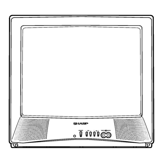
Page 4: Location Of User's Control
20MU14 LOCATION OF USER'S CONTROL... -
Page 5: Installation And Service Instructions
20MU14 INSTALLATION AND SERVICE INSTRUCTIONS Note: (1) When performing any adjustments to resistor controls and transformers use non-metallic screwdrivers or TV alignment tools. (2) Before performing adjustments, the TV set must be on at least 15 minutes. HIGH VOLTAGE CHECK CIRCUIT PROTECTION The receiver is protected by a 4.0A fuse (F701),... - Page 6 20MU14 For adjustments of this model, the bus data is converted to various analog signals by the D/A converter circuit. Note: There are still a few analog adjustments in this series such as focus and master screen voltage. Follow the steps below whenever the service adjustment is required. See "Table-B" to determine, if serv- ice adjustments are required.
- Page 7 20MU14 DATA SERVICE ADJUSTMENT ITEM ADJUSTMENT CONTENTS NUMBER RANGE INITIAL VALUE PICTURE 00-7F TINT 00-7F COLOR 00-7F BRIGHTNESS 00-7F SHARPNESS 00-3F Must be set to "24" VERTICAL PHASE 00-07 Must be set to "00" ~ "03" HORIZONTAL PHASE 00-1F RF-AGC...
-
Page 8: Service Adjustment
20MU14 Ë SERVICE ADJUSTMENT VCO Adjustment White Balance Adjustment 1. Connect a digital voltmeter between pin (44) of IC201 1. Receive a good local channel. and ground. 2. Enter the service mode and select the service 2. Receive a good local channel. -
Page 9: Description Of Schematic Diagram
20MU14 DESCRIPTION OF SCHEMATIC DIAGRAM WAVEFORM MEASUREMENT CONDITIONS: NOTES: 1. Photographs taken on a standard gated color bar 1. The unit of resistance "ohm" is omitted. signal, the tint setting adjusted for proper color. The (K=k =1000 , M=M ) wave shapes at the red, green and blue cathodes of 2. -
Page 10: Chassis Layout
20MU14 CHASSIS LAYOUT NORMAL PR701 C708... -
Page 11: Block Diagram
20MU14 BLOCK DIAGRAM... -
Page 12: Schematic Diagrams
20MU14 SCHEMATIC DIAGRAM: MAIN-1 Unit... - Page 13 20MU14...
- Page 14 20MU14 SCHEMATIC DIAGRAM: CRT Unit...
-
Page 15: Printed Wiring Board Assemblies
20MU14 PRINTED WIRING BOARD ASSEMBLIES PWB-A: MAIN Unit (Wiring Side) - Page 16 20MU14 PWB-A: MAIN Unit (Chip Parts Side)
- Page 17 20MU14 PWB-B: CRT Unit (Wiring Side) PWB-B: CRT Unit (Chip Parts Side)
-
Page 18: Replacement Parts List
3. PART NO. 4. DESCRIPTION IC2040 VHIPST994C/-1+ PST994C IC2102 VHIBR24L16F-1Y BR24L16F in USA: Contact your nearest SHARP Parts Distributor to order. TRANSISTORS For location of SHARP Parts Distributor, Please call Toll- Free; 1-800-BE-SHARP Q101 VS2SC945AQ/-1+ 2SC945AQ Q201 VS2SC2735//1EY 2SC2735 Q451 VS2SA1530R/-1Y 2SA1530R... - Page 19 20MU14 « « Ref. No. Part No. Description Code Ref. No. Part No. Description Code PWB-A: DUNTKA358WEX1 CAPACITORS MAIN UNIT (Continued) C516 VCKYCY1HB222KY 2200p Ceramic C517 VCEA0A1CW226M+ C520 VCEA0A1HW107M+ PACKAGED CIRCUITS C530 VCFYFA1HA334J+ 0.33 Mylar CF2040 RFILA0099CEZZ+ FILTER C531 VCFYFA1HA564J+ 0.56...
- Page 20 20MU14 Ref. No. Part No. « Description Code « Ref. No. Part No. Description Code PWB-A: DUNTKA358WEX1 R527 VRD-RA2BE223JY 1/8W Carbon R528 VRD-RA2BE272JY 2.7k 1/8W Carbon MAIN UNIT (Continued) R529 VRD-RA2BE472JY 4.7k 1/8W Carbon R604 VRS-RG3DB682J+ 6.8k M-Ox. RESISTORS R605...
-
Page 21: Miscellaneous Parts
20MU14 Ref. No. Part No. « Description Code Ref. No. Part No. « Description Code PWB-A: DUNTKA358WEX1 MISCELLANEOUS PARTS MAIN UNIT (Continued) P651 QPLGN0361CEZZA PLUG (3 PINS) RHU P701 QPLGN0260CEZZ PLUG (2 PINS) RESISTORS (Continued) P751 QPLGN0461CEZZA PLUG (4 PINS) RHU... -
Page 22: Packing Parts
20MU14 Ref. No. Part No. « Description Code Ref. No. Part No. « Description Code PACKING PARTS MISCELLANEOUS PARTS (NOT REPLACEMENT ITEM) ACC701 QACCDA015WJPZ AC-CORD SPAKCB228WJZZ PACKING CASE VSP0080PBK98A SPEAKER SPAKP0102GJZZ LAMIFOAM (457MM X 1800MM) QCNW-2111PEZZ WIRE (YBN) SPAKX0003GJZZ PACKING FOAM... -
Page 23: Packing Of The Set
20MU14 PACKING OF THE SET Polyethylene Bag Operation Manual Infrared R/C Unit Batteries Wrapping Paper Buffer Material FRONT Packing Case Use tape to fix the top side of packing case. REAR Use 10 staples to fix the bottom side of packing case. - Page 24 QRC0003-L Dec. 2003 Modify : SEMEX Design and Production Information Design base : JAPAN SHARP ELECTRONICA MEXICO S. A. DE C. V. Production : SEMEX Quality & Reliability Control Center Blvd. SHARP No. 3510 Parque Industrial Rosarito Playas de Rosarito, México B. C. 22710...