Table of Contents
Advertisement
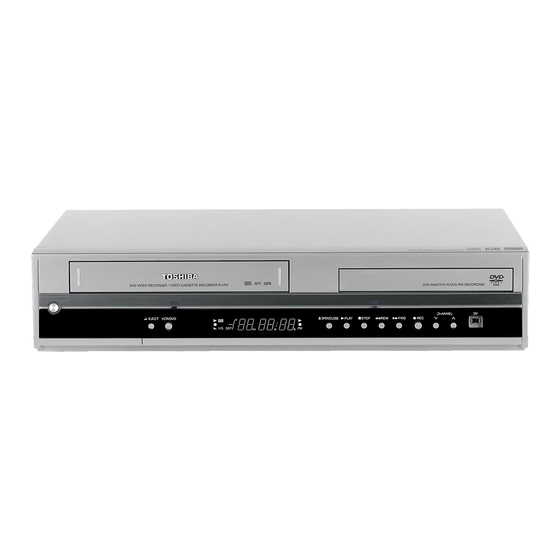
SERVICE MANUAL
Hi-Fi VCR & DVD VIDEO
RECORDER
The above model are classified as green products (*1), as indicated by the underlined serial numbers.
This Service Manual describes replacement parts for the green products. When repairing these green
product(s), use the part(s) described in this manual and lead-free solder (*2).
For (*1) and (*2), see the next page.
D-VR5SU
D-VR5SC
DOCUMENT CREATED IN JAPAN, April, 2006 GREEN
FILE NO. 810-200619GR
DOCUMENT CREATED IN JAPAN, APRIL, 2006
Advertisement
Chapters
Table of Contents

Related Manuals for Toshiba D-VR5SU


Summary of Contents for Toshiba D-VR5SU
- Page 1 SERVICE MANUAL Hi-Fi VCR & DVD VIDEO RECORDER D-VR5SU D-VR5SC The above model are classified as green products (*1), as indicated by the underlined serial numbers. This Service Manual describes replacement parts for the green products. When repairing these green product(s), use the part(s) described in this manual and lead-free solder (*2).
- Page 2 Hazardous Substances. From July 1, 2006, the RoHS Directive will prohibit any marketing of new products containing the restricted substances. Increasing attention is given to issues related to the global environmental. Toshiba Corporation recognizes environmental protection as a key management tasks, and is doing its utmost to enhance and improve the quality and scope of its environmental activities.
-
Page 3: Owner's Manual
Tape playback D-VR5SU Recording OWNER’S MANUAL Editing the disc Dubbing Additional information ©2006 Toshiba Corporation This device does not tape-record copy protected DVD Video Discs. Printed in Thailand 2 40101A SH 06/02 Introduction SAFTY PRECAUTIONS IMPORTANT SAFEGUARDS The lightning flash with arrowhead symbol, within an 1. -
Page 4: Table Of Contents
Introduction IMPORTANT SAFEGUARDS IMPORTANT SAFEGUARDS 13. LIGHTNING 19. REPLACEMENT PARTS When replacement parts are required, be sure the service technician uses replacement parts specified by To protect your unit from a lightning storm, or when it is left unattended and unused for long periods of time, the manufacturer or those that have the same characteristics as the original part. - Page 5 ROM drive, therefore, will not playback recorded vid- • When you record a TV program of a bilingual broad- DVD-RW • Toshiba is not liable for any damage or loss caused eos. cast, only one of the audio modes can be recorded.
-
Page 6: Parts And Functions
Introduction Parts and functions Parts and functions Front Display window * This unit has a door on the front panel. Please open it to access the S-VIDEO jack and the AUDIO (L/R)/VIDEO IN (INPUT 2) jacks. Display window VCR/DVD button OPEN/CLOSE button PLAY button VCR indicator... -
Page 7: Antenna Connections
Introduction Antenna connections Antenna connections If you are using an antenna system, follow these instructions. If you are using a Cable TV subscriber, skip DVD/VCR TO TV CONNECTION ahead to page 18 for the proper connections. After you have connected the antenna to the DVD/VCR, you must connect the DVD/VCR to the TV. ANTENNA TO DVD/VCR CONNECTION Below are 3 common methods of connecting your DVD/VCR to a TV. -
Page 8: Connections With The Tv Or Audio Component
Introduction Connections with the TV or audio component Connections with the TV or audio component Connect to a TV with HDMI output The exact arrangement you use to interconnect various video The unauthorized recording, use, distribution, and audio components to the DVD/VCR is dependent on the HDMI stands for High Definition Multimedia Interface. -
Page 9: Setting The Language
Various settings Setting the language SETUP MENU The SETUP MENU consists of several menus where Press to select the desired submenu and You can choose the language of the menu screen, Selectable languages: you can make various settings concerning lan- press ENTER. -
Page 10: Setting The Disc
Various settings Setting the disc Setting the disc / Other (SYSTEM SETUP) NEW DISC FORMAT You can format, protect, or finalize a disc. NOTES: NOTES: If you insert an unused DVD-RW disc, the disc is auto- • During finalizing, the cursor will move repeatedly. •... -
Page 11: Playback Procedure
Various settings Setting the audio / Setting the recording Setting the channel / Setting other items This DVD/VCR is equipped with a channel memory You can set the switching interval between played SAP (Second Audio Program) INITIAL REC MODE feature that allows you to skip channels up or down back images in the slide show mode. -
Page 12: Checking Media Information
Disc playback Checking media information Special playback Fast forward playback Press SEARCH during normal playback. Preparation: Various information on the loaded Each press of SEARCH will increase the speed of the search NOTE: There may be a slight de- • Turn ON the TV and set it to the video input mode. disc can be displayed on the TV (x2), (x12),... -
Page 13: Various Operations On Cd
Disc playback Title selection / DVD menu Changing angles / Zooming / Karaoke playback Changing angles Title selection When playing back a disc recorded with multi-angle facility, you Two or more titles are recorded on some discs. If the title menu is can change the angle that you are viewing the scene from. - Page 14 MP3 and WMA formats, prior to the downloading thereof. Toshiba has no right to grant and does not grant permission to download any To return to the thumbnail screen, press RETURN.
-
Page 15: Loading And Unloading A Cassette Tape
Disc playback Tape playback ® MP3/WMA/JPEG/DivX playback Loading and unloading a cassette tape ® Playing back DivX video files ® Press to select DivX file. • If the disc includes more than 10 files, you can move to the next Use only video cassette tapes marked or previous page. -
Page 16: Recording A Tv Program
Tape playback Recording ZERO RETURN function / Video index search system Read this before recording on disc Types of disc Press DISPLAY. This section explains what you must The counter display shows the tape running You can use DVD-RAM, DVD-RW and DVD-R discs to record video. 8 : 47 know to record onto a disc. -
Page 17: Timer Recording
Recording Recording a TV program One-touch Timer Recording (OTR) To stop recording Preparation: Press STOP to stop recording. • Turn ON the TV and set to the video input mode. The One-touch Timer Recording “ ” will appear on the screen for about 4 •... -
Page 18: Stereo Recording And Playback
Recording Timer recording Chase Playback SETUP MENU While recording a TV program onto the DVD-RAM disc, press PLAY to start chase playback. TIMER REC SET You can begin playback from the The TV program as it is being recorded will played back. TYPE ONCE MODE... -
Page 19: Editing A Playlist
Editing the disc Editing a playlist Editing a playlist Preparation: You can create and edit the playlist • Turn ON the TV and set to the video input mode. Changing a title name based on the original title. • Load the recorded DVD-RAM/RW (VR). •... -
Page 20: Editing An Original Title
Editing the disc Editing a playlist Editing a playlist Combining the title You can create a playlist by combining the several original titles or playlists. Erasing a playlist To combine the titles, it is necessary to create a playlist at first. By You can erase the created playlist. -
Page 21: Changing A Disc Name
Editing the disc Editing an original title Editing an original title Erasing a scene (Edit title) COMBINE CHAPTERS You can erase an unnecessary scene from the original title. Erase the scene after checking the title. You cannot restore the erased scene. -
Page 22: Dubbing A Disc Onto A Tape
Editing the disc Changing a disc name Changing a disc name Using the keyboard screen Character input 2 Erasing a character Press to select the type of letters in the Example: Explained here is the procedure when you You can erase the input character. list below and press ENTER. -
Page 23: Dubbing Using Other Equipment
Dubbing Dubbing using other equipment Dubbing using other equipment You can connect another VCR or camcorder to dubbing. You can connect a DV format digital video camera to the DV IN terminal to record from it. Typical connection: When using this unit as a recording device Playback VCR Playback Camcorder Playback Digital Video Camera... -
Page 24: Language Code List
Additional information Language code list Problems and troubleshooting Use the following check list for troubleshooting when you have problems with your unit. Consult your local dealer or Enter the appropriate code number for the initial settings “DVD MENU”, “AUDIO” and/or “SUBTITLE” (see page 25). service outlet if problems persist. -
Page 25: Specifications
Dimensions: Width : 16-15/16 inches (430 mm) Toshiba America Consumer Products, L.L.C. ("TACP") makes the following limited warranties to original consumers in Height : 3-5/8 inches (91.5 mm) the United States. THESE LIMITED WARRANTIES EXTEND TO THE ORIGINAL CONSUMER PURCHASER OR Depth : 13-3/16 inches (335.5 mm) - Page 26 • Place the unit on a workstation equipped to protect against static electricity, such as conductive mat. • Soldering iron with ground wire or ceramic type is used. • A worker needs to use a ground conductive wrist strap for body. A1-1 D-VR5SU/D-VR5SC...
-
Page 27: Important Service Safety Information
(Reading should not be above 0.5mA) Leakage Current Tester 1.5K ohm 0.15 µF PRODUCT UNDER TEST TEST PROBE Test all exposed KNOWN EARTH 2-Blade polarized metal surfaces GROUND type cord set Fig. 1 AC Leakage Test A1-2 D-VR5SU/D-VR5SC... -
Page 28: Important Safeguards
Do not push objects through any openings in this unit, as they may touch dangerous voltage points or short out parts that could result in fire or electric shock. Never spill or spray any type of liquid into the unit. A1-3 D-VR5SU/D-VR5SC... - Page 29 This reminder is provided to call the CATV system installer’s attention to Article 820-40 of the NEC that provides guidelines for proper grounding and, in particular, specifies that the cable ground shall be connected to the grounding system of the building, as close to the point of cable entry as practical. A1-4 D-VR5SU/D-VR5SC...
-
Page 30: Nec Section
EXAMPLE OF ANTENNA GROUNDING AS PER THE NATIONAL ELECTRICAL CODE ANTENNA LEAD IN WIRE GROUND CLAMP ANTENNA DISCHARGE UNIT (NEC SECTION 810-20) ELECTRIC SERVICE EQUIPMENT GROUNDING CONDUCTORS (NEC SECTION 810-21) GROUND CLAMPS POWER SERVICE GROUNDING NEC-NATIONAL ELECTRICAL CODE ELECTRODE SYSTEM (NEC ART 250, PART H) S2898A A1-5 D-VR5SU/D-VR5SC... -
Page 31: Disc Removal Method At No Power Supply
Remove the Top Cabinet. (Refer to item 1 of the DISASSEMBLY INSTRUCTIONS.) Insert a fine rod (wire etc.) into the hole of the DECK CD as shown by the arrow. (Refer to Fig. 1) The Tray is opened. Manually open the Tray. DECK CD hole Fig. 1 A1-6 D-VR5SU/D-VR5SC... -
Page 32: Tray Lock
Press and hold the '0' key on the remote control unit. Simultaneously press and hold the 'STOP' key on the front panel. Hold both keys for more than 2 seconds. The Tray Lock has now been cleared. Turn Unit OFF. A1-7 D-VR5SU/D-VR5SC... - Page 33 INTERCONNECTION DIAGRAM ....................H-35, H-36 I-1~I-5 WAVEFORMS ..........................J1-1, J1-2 MECHANICAL EXPLODED VIEW ..................... J2-1, J2-2 CHASSIS EXPLODED VIEWS ....................MECHANICAL REPLACEMENT PARTS LIST ................. K1-1~K1-4 CHASSIS REPLACEMENT PARTS LIST .................. K2-1, K2-2 K3-1~K3-12 ELECTRICAL REPLACEMENT PARTS LIST ................D-VR5SU/D-VR5SC A2-1...
-
Page 34: Dvd-Ram
Power Consumption 29 W at 120V 60Hz Stand by (FIP Off) 2.5 W at 120V 60Hz Stand by 3.5 W at 120V 60Hz Per Year -- W Energy Star Protector Power Fuse Safety Circuit IC Protector (Micro Fuse) A3-1 D-VR5SU... - Page 35 English, French, Spanish VCR OSD English, French, Spanish G-11 Clock, Timer Calendar 1990/1/1 ~ 2081/12/31 and Timer Timer Events 12 Program / 1Month Back-up One Touch Recording Max Time 6 hours Timer Back-up (at Power Off Mode) 30min A3-2 D-VR5SU...
- Page 36 (VCR Side) Play (DVD Side) Pause / Still / Step (DVD Side) (DVD Side) RF Output CH Eject Stop FF / Cue REW / Review OTR (ITR) Hi-Fi CH/AV/DV HD(HDMI) CABLE Progressive Scan Out PBC (Play Back Control) A3-3 D-VR5SU...
- Page 37 REC MODE / SPEED DUBBING AUDIO / AUDIO SELECT MARKER ZOOM / ZERO RETURN REPEAT A-B ANGLE / COUNTER RESET SUBTITLE / ATR PLAY MODE / REPEAT CLOCK / COUNTER CHAPTER MARK NAVI MARK TV / VIDEO HDMI/PROGRESSIVE HDMI A3-4 D-VR5SU...
- Page 38 Yes (CD) Screen Saver Auto Stop Tray Lock Audio DAC 192kHz / 24bit Closed Caption signal in VBI (DVD Playback) Features Auto Head Cleaning (VCR) Auto Power Off Forward/Reverse Picture Search Index Search SQPB Rec End Search CS Easy A3-5 D-VR5SU...
-
Page 39: Remote Control
Audio In RCA x 2 (L/MONO,R White,Red) Detect Input / Output Bit Stream Input / Output RF Input / Output BS Input / Output Euro Scart AC Inlet Indicator Power T-Rec TV/VCR Yes (Green) Yes (Green) Surround Level Meter A3-6 D-VR5SU... - Page 40 80 cm Container Stuffing 1,530 Sets/40' container G-20 Material Cabinet Front PS 94V2 or More / DECABROM Non-Halogen Demand Eyelet Demand G-21 Environment Environmental standard requirement (by buyer) Green procurement of TOSHIBA Pb-free Phase3 (Phase3A) Measures for Whisker A3-7 D-VR5SU...
- Page 41 GENERAL SPECIFICATIONS DVD-R/-RW/-RAM Video Recorder & VHS Outline of the product Player/Recorder DVD System Color System NTSC Disc Format DVD-R (Class0) DVD-RW (Class0&1) DVD-RAM (Class0) DVD-R/-RW/-RAM, DVD-Video, CD-DA, CD-R/- Play RW, Video CD, SVCD Disc Diameter 120 mm 80 mm (Self Recording/Playback Only) Deck DVR-L11SOR Rec Time...
- Page 42 GENERAL SPECIFICATIONS Regulation Safety UL/CSA Radiation FCC/IC Laser DHHS Temperature Operation 5oC - 35oC Storage -20oC - 60oC Operating Humidity Less than 80% RH Signal Video Signal Output Level 1 V p-p / 75 ohm (DVD, VCR) S/N Ratio (Weighted) 65dB (DVD-Video) 50dB (VCR) Horizontal Resolution...
- Page 43 GENERAL SPECIFICATIONS G-12 Display Display Display Type 6Digit Fluorescent Indicator Yes (12h) Clock Counter Yes (hour: min: sec) Yes (hour: min: sec) Yes (hour: min: sec) TV/VIDEO VR Mode Video Mode DVD-R DVD-RW DVD+R DVD+RW DVD-RAM Disc In Tape In T-Rec Counter Remain Chapter...
-
Page 44: Dvd Menu
GENERAL SPECIFICATIONS G-13 Remote Unit RC-KZ Control Glow in Dark Remocon Format TOSHIBA Remocon Format TOSHIBA Custom Code 45-BC Power Source Voltage (D.C) UM size x pcs UM-4 x 2 pcs Total Keys 51 Keys Keys POWER OPEN/CLOSE/EJECT 0 / 10... -
Page 45: Undo Finalize
GENERAL SPECIFICATIONS G-14 Features Auto Power Off (DVD & VCR) CM Skip (30sec x 6 Times) Copy (Tape to Disc, Disc to Tape) Yes (By Conditioning) VIDEO PLUS+ (SHOWVIEW, G-CODE) Auto CH Memory CH Set-Up Add/Delete Area Code Clock Set Yes (Calendar 12H) Just Clock Auto Clock Set... - Page 46 GENERAL SPECIFICATIONS G-15 Accessories Owner's Manual Language English/French w/Guarantee Card Remote Control Unit Battery UM size x pcs UM-4 x 2 pcs OEM Brand Blank DVD-RW DISC (4.7GB) Blank DVD-R DISC (4.7GB) Blank DVD-RAM Disc (4.7GB) Guarantee Card Registration Card Warning Sheet Service Station List Important Tag...
- Page 47 80 cm Container Stuffing 1,530 Sets/40' container G-20 Material Cabinet Front PS 94V2 or More / DECABROM Non-Halogen Demand Eyelet Demand G-21 Environment Environmental standard requirement (by buyer) Green procurement of TOSHIBA Pb-free Phase3 (Phase3A) Measures for Whisker A3-14 D-VR5SC...
- Page 48 Disconnect the following connector: (CP5751). Remove the 2 screws 4. Remove the DV PCB Block in the direction of arrow (D). Deck CD Angle DVD (L) Flap Fig. 1-2 CP5751 Angle DVD (R) DV PCB Block CP5701 CP4001 CP1704 Fig. 1-4 B1-1 D-VR5SU/D-VR5SC...
- Page 49 Move the Cassette Holder Ass’y to the back side. Remove the 3 screws 3. Disconnect the following connectors: (CP101, CP102, CP3001). Remove the AC Head Cover and VCR Deck in the Bottom Plate direction of arrow. Fig. 1-7 B1-2 D-VR5SU/D-VR5SC...
-
Page 50: Removal Of Vcr Deck Parts
Move the Cassette Holder Ass'y to the front side. Push the Locker R to remove the Cassette Side R. Remove the Cassette Side L. Locker R Flap Lever Main Chassis Cassette Side R Link Lever Fig. 2-4 Link Unit Main Chassis Cassette Side L Fig. 2-2 B2-1 D-VR5SU/D-VR5SC... - Page 51 Fig. 2-6-D. Loading Motor In case of the Tension Connect installation, install as the circled section of Fig. 2-6-E. Cassette Opener Tension Band Fig. 2-5-C Tension Connect Pink Fig. 2-6-C Loading Motor Capstan DD Unit White Fig. 2-5-D B2-2 D-VR5SU/D-VR5SC...
- Page 52 2-8: S REEL/T REEL/IDLER ARM ASS’Y/IDLER GEAR (Refer to Fig. 2-8-A) Idler Arm Ass’y Remove the S Reel and T Reel. Clutch Gear Remove the 2 Polyslider Washers 1. Fig. 2-8-C Remove the Idler Arm Ass’y and Idler Gear. B2-3 D-VR5SU/D-VR5SC...
- Page 53 Cylinder Unit Ass'y then tighten the screw (2), finally tighten the screw (3). A/C Head A/C Head Spring A/C Head Base • Screw Torque: 3 ± 0.5kgf•cm Fig. 2-12 • Screw Torque: 5 ± 0.5kgf•cm (Screw 1) Fig. 2-10-A B2-4 D-VR5SU/D-VR5SC...
- Page 54 Tension Lever Remove the E-Ring 1, then remove the Main Cam. Remove the E-Ring 2, then remove the Pinch Roller Loading Arm S Unit Cam and Joint Gear. Main Cam Fig. 2-15-A Pinch Roller Cam Joint Gear Fig. 2-14-A B2-5 D-VR5SU/D-VR5SC...
- Page 55 1. In case of the Clutch Ass’y installation, install it with inserting the spring of the Clutch Ass’y into the dent of the Coupling Gear. (Refer to Fig. 2-16-B) [OK] Cassette Guide Post Clutch Ass’y [NG] Cassette Guide Post Coupling Gear Fig. 2-17-C Fig. 2-16-B B2-6 D-VR5SU/D-VR5SC...
- Page 56 Shield Wire. (Refer to Fig. 3-4.) NOTE Do not move the Braided Shield Wire in the vertical Blower type IC direction towards the IC pattern. desoldering machine Braided Shield Wire Soldering Iron Fig. 3-2 IC pattern Fig. 3-4 B3-1 D-VR5SU/D-VR5SC...
- Page 57 Fig. 3-6 3. Absorb the solder left on the lead using the Braided Shield Wire. (Refer to Fig. 3-7.) NOTE Do not absorb the solder to excess. Soldering Iron Braided Shield Wire Fig. 3-7 B3-2 D-VR5SU/D-VR5SC...
- Page 58 Fast Forward, Flipflop SENS Sensor Frequency Generator Search Mode FL SW Front Loading Switch Serial Input Frequency Modulation Sound Intermediate Frequency Frequency Sub Carrier Serial Output Forward Solenoid Generator Standard Play Ground Serial Strobe H.P.F High Pass Filter Switch C1-1 D-VR5SU/D-VR5SC...
- Page 59 UNREG Unregulated Volt Voltage Controlled Oscillator Video Intermediate Frequency Vertical Pulse, Voltage Display V.PB Video Playback Variable Resistor V.REC Video Recording Visual Search Fast Forward Visual Search Rewind Voltage Super Source V-SYNC Vertical-Synchronization Voltage Tuning X’TAL Crystal Luminance/Chrominance C1-2 D-VR5SU/D-VR5SC...
-
Page 60: Service Mode List
DVD mode STOP 2 sec. NOTE: The function will only work without the setting of DVD disc (No disc) at DVD mode. DVD mode Region setting. STOP 2 sec. (STOP) Refer to the “WHEN REPLACING NEW DVD LOADER”. C2-1 D-VR5SU/D-VR5SC... - Page 61 Romcorrection data check sum. PLAY/REC 0000 PLAY/REC total hours. = (16 x 16 x 16 x thousands digit value) Fig. 1 + (16 x 16 x hundreds digit value) + (16 x tens digit value) + (ones digit value) C3-1 D-VR5SU/D-VR5SC...
- Page 62 Clean the full erase head in the same manner. (Refer to the figure below.) Do not exert force against the cylinder head. Do not move the chamois upward or downward on the head. Use the chamois one by one. Cylinder Head Audio Control Head C3-2 D-VR5SU/D-VR5SC...
- Page 63 Press both CH UP button on the set and the PLAY button on the set for more than 2 seconds. After the finishing of the initializing of shipping, the unit will turn off automatically. The unit will now have the correct DATA for the new MEMORY IC. C4-1 D-VR5SU/D-VR5SC...
- Page 64 Press both CH UP button on the set and the PLAY button on the set for more than 2 seconds. After the finishing of the initializing of shipping, the unit will turn off automatically. The unit will now have the correct DATA for the new MEMORY IC. C4-2 D-VR5SU/D-VR5SC...
-
Page 65: When Replacing New Dvd Loader
Information screen will be displayed on the TV Monitor. (Refer to Fig. 1) If the writing Region No. is appeared, the Region setting is completed. Turn off the power. Vaddis Timer Ver. RXH63011-T OEC0161A118B C.Sum 0B010065 10D3 Accum 000000 0000 PIONEER DVD-RW DVR-L11RM 1.30 Region No. Region-1 Fig. 1 C4-3 D-VR5SU/D-VR5SC... -
Page 66: Re-Write For Dvd Firmware
Information screen will be displayed on the TV Monitor. (Refer to Fig. 1) When the changed version displays, the Re-write will be completed. Turn off the power Firmware Version Vaddis Timer Ver. RXH63011-T OEC0161A118B C.Sum 0B010065 10D3 Accum 000000 0000 PIONEER DVD-RW DVR-L11RM 1.30 Region-1 Fig. 1 C5-1 D-VR5SU/D-VR5SC... -
Page 67: Servicing Fixtures And Tools
In case of using a cassette tape, press the EJECT button to insert or eject a cassette tape. Turn on the power and re-check the cable before checking the trouble points. When you servicing with connection of DVD, perform the operations above step 2 to step 3. D1-1 D-VR5SU/D-VR5SC... -
Page 68: Mechanical Adjustments
50~90gf•cm during playback in SP mode. 10(+0.2, -0)mm Confirm that the left meter of the torque tape indicates 25~40gf•cm during playback in SP mode. Tentelometer (JG185) Height Adjustment Washer 2.6x4.7xT0.13 Video Tape 2.6X4.7xT0.25 Fig. 1-1-B Guide Roller P1 Post Fig. 1-3 D2-1 D-VR5SU/D-VR5SC... - Page 69 Cassette Holder Ass'y Envelope Fig. 1-4-A (TP101) Torque Gauge/Adapter CH-1 CH-2 (JG002F/JG002B) Track Track CH-2 SW Pulse (TP3001) Torque Gauge/Adapter (JG002E/JG002B) Fig. 2-1-A Entrance Exit S Reel Fig. 1-4-B T Reel A : B ≥ 3 : 2 Fig. 2-1-B D2-2 D-VR5SU/D-VR5SC...
- Page 70 Audio/Control Head picture and sound again. Reflected picture of Stamp Mark P4 Cap Stamp Mark Fig. 2-2-A Audio/Control Head [OK] [NG] Fig. 2-2-B Audio/Control Head Tape 0.25±0.05mm Fig. 2-2-C D2-3 D-VR5SU/D-VR5SC...
- Page 71 3. MECHANISM ADJUSTMENT PARTS LOCATION GUIDE 1. Tension Connect P4 Post 2. Tension Arm T Brake Spring 3. Guide Roller T Reel 4. Audio/Control Head S Reel 5. X value adjustment driver hole Adjusting section for the Tension Arm position D2-4 D-VR5SU/D-VR5SC...
- Page 72 2 seconds to set tracking to center. Press both VCR/DVD button on the set and the REC button on the set for more than 2 seconds. CH-2 6.5H CH-1 Fig. 1-1-A CH-2 CH-1 6.5H Fig. 1-1-B D-VR5SU/D-VR5SC D3-1...
- Page 73 DVD/HD MPEG MT PCB CD102 CP103 FE HEAD CP8301 CD103 AC HEAD CP8302 CP653 CP7304 CP5701 OS651 J653 J652 J651 J655 CP4001 CP7301 CP7303 VCR MT PCB CD1701 CD7301 CD7303 CD7305 CD4001 OPERATION PCB CP5751 DV PCB DECK CD D3-2 D-VR5SU/D-VR5SC...
-
Page 74: Troubleshooting Guide
Check of T501 Does display light ? linked to L506 ? and peripheral circuit. Check of V651 and peripheral circuit. Is the voltage at Check of IC3001. pin 29 of IC3001 0V ? Check of T501 and peripheral circuit. D-VR5SU/D-VR5SC... - Page 75 Inserting a cassette and push play button. Does the power cut Check CAPSTAN DD UNIT after 3 seconds ? and CYLINDER UNIT. Does the power cut Check Q3001, Q3002 after about 6 seconds ? and CAPSTAN BELT. Check the POWER BLOCK. D-VR5SU/D-VR5SC...
- Page 76 TROUBLESHOOTING GUIDE AT PLAYBACK AND RECORDING, CYLINDER MOTOR UNLOAD Is the voltage at pin 8 of Check IC502. CP3001 about DC12.6V ? In playback, is at pin 12 of Check IC3001. CP3001 about DC2.6V ? Check the DECK BLOCK. D-VR5SU/D-VR5SC...
- Page 77 Change AUDIO HEAD. scratched ? At playback, is input about Change CAPSTAN DD UNIT. 4.5Vp-p of a rectangular wave at pin 9 of IC3001 ? At playback, is pin 5 of Check IC3001. CP3001 3.5V ? Check AUDIO BLOCK. D-VR5SU/D-VR5SC...
- Page 78 When a CASSETTE can Check LED of DECK, not inserted, is pin 25 of PHOTO SENSOR. IC3001 5V ? When a CASSETTE is Change inserted, is pin 8 of LOADING MOTOR. CP3001 12.6V ? Check circuit of POWER BLOCK. D-VR5SU/D-VR5SC...
- Page 79 Defective CASSETTE Does another CASSETTE or CASSETTE LOADING insert ? BLOCK. Does SW3001 and Correctly SW3001 REC LEVER and REC LEVER set. correctly set ? After inserting CASSETTE, is pin 51 Check SW3001. of IC3001 0V ? Check IC3001. D-VR5SU/D-VR5SC...
- Page 80 TROUBLESHOOTING GUIDE CAN NOT FF/REW At FF/REW, does voltage Check of IC3001. at pin 9 of IC3001 change ? Check DECK MECHANISM. D-VR5SU/D-VR5SC...
- Page 81 At play, is the voltage at pin 12 of CP3001 2.6V ? Change CYLINDER unit. Is PG PULSE signal Is there HEAD SW inputted to pin 104 PULSE at TP3001? of IC3001 ? Change IC3001. Check Q3001 and Q3002. D-VR5SU/D-VR5SC...
- Page 82 TROUBLESHOOTING GUIDE AT PLAY, THE PICTURE JITTERS VERTICAL MINUTELY Is FG wave of CP3001 Change at pin 11 5V ? CYLINDER MOTOR. Change IC3001. Is pin 12 of CP3001 2.6V ? Change CYLINDER MOTOR. D-VR5SU/D-VR5SC...
- Page 83 Does the CTL pulse In auto tracking, is the signal (more than 0.6Vp-p) Check CONTROL HEAD. voltage at pin 89 of IC3001 appear at pin 7 of IC3001? more than 0.6Vp-p more than DC 0.2V ? Change IC3001. E-10 D-VR5SU/D-VR5SC...
- Page 84 MODE IS ACTIVE, UNIT STOPS IMMEDIATELY Refer to section "CAPSTAN Does CAPSTAN DD DD MOTOR NOT MOTOR rotate ? ROTAING". Is there REEL SENSOR Check Q3005 and Q3006. PULSE signal at pin 69 and 70 of IC3001? Change IC3001. E-11 D-VR5SU/D-VR5SC...
- Page 85 ? The height of GUIDE POST Is a height of GUIDE POST readjust. maximum ? Is PG SHIFTER Adjust PG SHIFTER. adjustment 6.5H ? Change IC101 Is a wave of PB-Y unusual ? and peripheral circuit. Change IC101. E-12 D-VR5SU/D-VR5SC...
- Page 86 Change IC3001. at pin 17 of IC3001? Is there video signal Change IC3001. at pin 19 of IC3001? Is there video signal Change IC8302. at pin 21 of IC8302? Check at pin 5 of J8005 and peripheral circuit. E-13 D-VR5SU/D-VR5SC...
- Page 87 26 of IC101? Is there video signal Change IC3001. at pin 17 of IC3001? Check J8001. Is there video signal Change IC8302. at pin 21 of IC8302? Check at pin 5 of J8005 and peripheral circuit. E-14 D-VR5SU/D-VR5SC...
- Page 88 Is there color signal in Change IC3001. video signal at pin 17 of IC3001 ? Is there color signal in Change IC8302. video signal at pin 21 of IC8302 ? Check at pin 5 of J8005 and peripheral circuit. E-15 D-VR5SU/D-VR5SC...
- Page 89 Is noisy a wave of video Change IC3001. signal at pin 17 of IC3001 ? Is noisy a wave of video Change IC8302. signal at pin 21 of IC8302 ? Check J8005 at pin 5 and peripheral circuit. E-16 D-VR5SU/D-VR5SC...
- Page 90 Check TU301, J8002, J653, Is there CHROMA signal at IC8302 and circuit around it. pin 32 of IC101 ? Is there CHROMA signal at Change IC101. pin 26 of IC101 ? Refer to "AT PLAYBACK, THE COLOR DOES NOT APPEAR". E-17 D-VR5SU/D-VR5SC...
- Page 91 Change IC101 and check Is there audio signal at pin peripheral circuit of pin 10 10 of IC101 ? of IC101. Check whether there are not a damage, dirt in AUDIO HEAD and peripheral circuit of pin 62 of IC701. E-18 D-VR5SU/D-VR5SC...
- Page 92 In playback, is there voltage Check POWER BLOCK. at pin 2 of CP3001 12V ? In playback, is there voltage Change IC3001. at pin 102 of IC3001 2.5V ? DD MOTOR rotate now ? If not, replace it. E-19 D-VR5SU/D-VR5SC...
- Page 93 TUNER pin 76, 78 and 80 of or audio input jack to IC701 . IC101 ? Is there a sine wave Change L101. at pin 5 of L101 ? Check lead wire of A/C HEAD and CONNECTOR. E-20 D-VR5SU/D-VR5SC...
- Page 94 TROUBLESHOOTING GUIDE THE CASSETTE INSERT, BUT THE TAPE DOES NOT MOVE Check LOADING MOTOR Does the mode and MODE SENSOR appear at display ? RELATION DEPARTMENT. Does operate with Check IC3001. remote control ? Check OPERATION PCB. E-21 D-VR5SU/D-VR5SC...
- Page 95 Is the voltage at pin 71 Is the BASE of Change IC3001. of IC3001 5V ? Q103 5V ? Is there video signal Change IC101. at pin 26 of IC101 ? Check CYLINDER UNIT and circuit around of CP101. E-22 D-VR5SU/D-VR5SC...
- Page 96 Check J8005 and peripheral Is there audio signal at circuit. pin 53 and 57 of IC701 ? Is there audio signal at Check J8002, J651, J652, pin 9 and 14 IC8302 and peripheral circuit. of IC701? Change IC701. E-23 D-VR5SU/D-VR5SC...
- Page 97 Change IC3001. of IC3001 5V ? Is there audio signal at Check IC8302, J8002 and pin 14 of IC701 ? J651. Is there audio signal at Change IC701. pin 61 of IC701 ? Check circuit around of J8005. E-24 D-VR5SU/D-VR5SC...
- Page 98 58 of IC701 12V ? Check IC8302, J8002, J651 Is there Audio signal at pin and J652. 9 and 14 of IC701 ? Is there Audio signal at Change IC701. pin 53 and 57 of IC701? Check circuit around of J8005. E-25 D-VR5SU/D-VR5SC...
- Page 99 13 of TU301. 21 of IC801 ? Is there audio signal at Change IC701. pin 53 and 57 of IC701 ? Is there audio signal a emitter of Check IC701. Q8020 and Q8021 ? Check circuit around of J8005. E-26 D-VR5SU/D-VR5SC...
- Page 100 Check circuit around of TU301. pin 21 of IC801 ? Is there audio signal at pin Change IC701. 53 and 57 of IC701 ? Is there audio signal Check IC701. a collector of Q8020 and Q8021 ? Check circuit around of J8005. E-27 D-VR5SU/D-VR5SC...
- Page 101 Check circuit of HEAD AMP Is there audio signal at and CYLINDER UNIT. pin 22 and 24 of IC701 ? Is there audio signal at Change IC701. pin 53 and 57 of IC701 ? Check circuit around of J8005. E-28 D-VR5SU/D-VR5SC...
- Page 102 14 of IC701 ? Is there audio signal at pin Change IC701. 53 and 57 of IC701 ? At recording and play, is Check CYLINDER UNIT. there signal at pin 7, 8 and 9 of CP101 ? Check IC701. E-29 D-VR5SU/D-VR5SC...
- Page 103 Check P.CON 12V and CP1704 about DC12V ? P.CON+D5V line of and pin 4 of CP1704 about POWER BLOCK. DC5V ? Is the lose connection Check CD1701 connection at CD1701 to CP1704 to CP1704 and DECK. and DECK ? Check DECK. E-30 D-VR5SU/D-VR5SC...
- Page 104 Check IC4009 and M17,N17~N20, P17~P20 peripheral circuit. and R18~R20 of IC4001 ? Is there signal out at pin Check IC4001 and F17,F18, G18, E17 and H17 of IC4001 with each peripheral circuit. out put mode ? Check VCR BLOCK. E-31 D-VR5SU/D-VR5SC...
- Page 105 Check IC7301 and peripheral pin 10, 11 and 12 of circuit. IC7301 ? Is there a signal out at Check IC7301 and peripheral pin 15, 16,17 and 18 of circuit. IC7301 ? Go to NO AUDIO ON PLAYBACK. E-32 D-VR5SU/D-VR5SC...
- Page 106 Check IC7301 and peripheral pin 10, 11 and 12 of circuit. IC7301 ? Is there a signal out at Check IC7301 and peripheral pin 15, 16,17 and 18 of circuit. IC7301 ? Go to NO AUDIO ON PLAYBACK. E-33 D-VR5SU/D-VR5SC...
- Page 107 OF AV JACK Is there VIDEO signal Check IC4001 and peripheral at pin G18 and H17 of circuit. IC4001 ? Check IC8302 and peripheral Is the waveform at pin circuit. 21 of IC8302 ? Check J8005 and peripheral circuit. E-34 D-VR5SU/D-VR5SC...
- Page 108 G18 of IC4001 ? Check CP7301 connection Is there Y signal at pin to CP8301. 23 of CP7301 ? Check IC8302 and Is there Y signal at pin peripheral circuit. 32 of IC8302 ? Check J8003 and peripheral circuit. E-35 D-VR5SU/D-VR5SC...
- Page 109 H17 of IC4001 ? Check CP7301 connection Is there C signal at to CP8301. pin 25 of CP7301 ? Check IC8302 and Is there C signal at pin peripheral circuit. 30 of IC8302 ? Check J8003 and peripheral circuit. E-36 D-VR5SU/D-VR5SC...
- Page 110 F18 of IC4001 ? Check CP7301 connection Is there Y signal at to CP8301. pin 21 of CP7301 ? Check IC8302 and peripheral Is there Y signal at circuit. pin 36 of IC8302 ? Check J8006 and peripheral circuit. E-37 D-VR5SU/D-VR5SC...
- Page 111 Is there U & V signals Check CP7301 connection at pin 17 and 19 of to CP8301. CP7301 ? Is there U & V signals Check IC8302 and peripheral at pin 34 and 35 of circuit. IC8302 ? Check J8006 and peripheral circuit. E-38 D-VR5SU/D-VR5SC...
- Page 112 Is there AUDIO signal at pin Check IC7301 and peripheral 15, 16, 17 and 18 of IC7301 ? circuit. Check IC8301 and peripheral Is there waveform at pin circuit. 1 and 7 of IC8301 ? Check J8004 and peripheral circuit. E-39 D-VR5SU/D-VR5SC...
- Page 113 Check IC4009 and peripheral pin D19, E18, H18 and circuit. J18 of IC4001 ? Is there a signal out at Check IC4001, DVD DECK pin E17, F17, F18, G18 and peripheral circuit. and H17 of IC4001 ? Check VCR BLOCK. E-40 D-VR5SU/D-VR5SC...
- Page 114 Is there a signal in at pin 9, 10 and 12 of IC7301 ? and peripheral circuit. Is there a signal out at pin Check IC7301 and peripheral 15, 16, 17 and 18 of circuit. IC7301 ? Check VCR BLOCK. E-41 D-VR5SU/D-VR5SC...
- Page 115 (POWER PCB ASS'Y) PCB010 (VCR MT PCB ASS'Y) 102B 102A 101E 101L 101U 101O 101P 101K 101A 101J 101H 101N 101T 101Q 101V 101F 101I 101M 101B 101G 101C 101W 101R 101S 101W 101D PCB270 (OPERATION PCB ASS'Y) J1-1 D-VR5SU/D-VR5SC...
- Page 116 MECHANICAL EXPLODED VIEW (PACKING DIAGRAM) 132, 133, 134, 135, 136, 137 CD6002, CD6003 TM601 J1-2 D-VR5SU/D-VR5SC...
- Page 117 CHASSIS EXPLODED VIEW (TOP VIEW) CD1501 M2003 UN4001 H5002 H5001 CD1502 M101 NOTE: Applying positions AA for the grease are displayed for this section. CLASS MARK Check if the correct grease is applied for each position. GREASE J2-1 D-VR5SU/D-VR5SC...
- Page 118 CHASSIS EXPLODED VIEW (BOTTOM VIEW) M2001 CD1501 CD1502 NOTE: Applying positions AA for the grease are displayed for this section. CLASS MARK Check if the correct grease is applied for each position. GREASE J2-2 D-VR5SU/D-VR5SC...
- Page 119 795WCAA303 PAD DVD/VR 155*250 AE007251 795WCAA322 PAD(M2G1) AE008495 JB5ND500 POLYBAG INSTRUCTION(RED CAUTION) AE008541 J2G00128A WARNING SHEET AE008542 J2J40101A INSTRUCTION BOOK AE008543 J2J40107A QUICK SET-UP SHEET(SPANISH) AE007451 J3N51617A REGISTRATION CARD AE007627 J5S10229A INFORMATION SHEET(USA) AE008544 A2J401H975 INSTRUCTION BOOK KIT K1-1 D-VR5SU...
- Page 120 811022680U SCREW TAP TITE(P) BIND 2.6*8 CH AE007202 810923053U SCREW TAP TITE(B) R BIND 3*5.3 CH AE006822 8110E2680U SCREW TAP TITE(P) WH10 M2.6*8 CH AE007212 810213060U SCREW PAN M3*6 CH AE005659 8109I3080U SCREW TAP TITE(B) WH7 3*8 CH K1-2 D-VR5SU...
- Page 121 MECHANICAL REPLACEMENT PARTS LIST Location No. TSB P/N Reference No. Description AE008507 7A7010203A FRONT CABI ASS'Y 101A AE008508 701WPJ1424 CABINET FRONT 101B AE008509 711WPB0024 DOOR 101C AE008510 711WPD0698 PLATE DISPLAY2 101D AE008511 711WPD0699 PLATE DISPLAY1 101E AE008512 712WPJ0953 FLAP VCR 101F AE008513 712WPJ0954...
- Page 122 MECHANICAL REPLACEMENT PARTS LIST Location No. TSB P/N Reference No. Description AE006673 8109130B7U SCREW TAP TITE(B)R PAN 3*27 CH AE005474 810923070U SCREW TAP TITE(B) R BIND 3*7 CH AE003526 810923080U SCREW TAP TITE(B) BIND 3*8 CH AE004724 8109K3060U SCREW TAP TITE(B) BIND(3D) 3*6 CH AE003524 8109I30A0U SCREW TAP TITE(B) WH7 3*10 CH...
- Page 123 HEAD,AUDIO CONTROL VTR-1X2RPE22-772 H5002 AD301676 1543Q02014 HEAD (FULL ERASE) VTR-1X2ERS11-154 ! M101 AE005552 1596S98002 MOTOR,LOADING MDB2B66B ! M2001 AE005853 1510S98044 CAPSTAN DD UNIT F2QVB73B ! M2003 AE006792 1589S11025 MICRO MOTOR I20AL34K ! UN4001 AE006680 A2F401H500 CYLINDER UNIT ASS'Y A2F401H500 K2-1 D-VR5SU...
- Page 124 CHASSIS REPLACEMENT PARTS LIST Location No. TSB P/N Reference No. Description AE006675 A2G101H420A DECK ASSY A2G101H420A AE005514 85OA400245 PINCH ROLLER BLOCK VA2 AE006679 85OP900759 LEVER,FLAP(S) BZ710193 85OP200290 BELT,CAPSTAN (S) BZ710515 85OP600581 WORM AE005919 85OP500091 BASE,AC HEAD BZ710112 85OP800324 SPRING,AC HEAD AE006676 85OA000529 MAIN CHASSIS ASS'Y(S)
- Page 125 AD301537 0021E5Q210 LTL-1CHGE-002A D701 BZ410006 D1VT001330 DIODE,SILICON 1SS133T-77 D1701 AE008590 D9WU05R62B DIODE,ZENER MTZJ5.6B-EIC D1703 AE008193 D9WU01002B DIODE,ZENER MTZJ10B-EIC D1704 BZ410006 D1VT001330 DIODE,SILICON 1SS133T-77 D1705 BZ410006 D1VT001330 DIODE,SILICON 1SS133T-77 D1709 AE008588 D9WU02702B DIODE,ZENER MTZJ27B-EIC D1710 AE008590 D9WU05R62B DIODE,ZENER MTZJ5.6B-EIC K3-1 D-VR5SU...
- Page 126 COMPOUND TRANSISTOR KRA103SRTK ! Q1712 BZ510057 TAAT01281Y TRANSISTOR,SILICON KTA1281_Y Q1713 BZ510067 TNAAC05002 COMPOUND TRANSISTOR KRC103SRTK Q1714 AE006629 TDA0016910 TRANSISTOR,SILICON KTD1691Y ! Q1715 BZ510077 TAAT012714 TRANSISTOR,SILICON KTA1271_Y-AT Q1716 BZ510067 TNAAC05002 COMPOUND TRANSISTOR KRC103SRTK Q1717 BZ510067 TNAAC05002 COMPOUND TRANSISTOR KRC103SRTK K3-2 D-VR5SU...
- Page 127 L1704 BZ310039 02167F220J COIL L3001 AE000773 021LA6120J COIL L5701 AE008553 02D6000085 COIL,CHOKE ACM2012-201-2P-T L5702 AE008553 02D6000085 COIL,CHOKE ACM2012-201-2P-T L5901 AE008306 02D6000073 COIL,CHOKE ACM2012H-900-2P-T L5902 AE008306 02D6000073 COIL,CHOKE ACM2012H-900-2P-T L5903 AE008306 02D6000073 COIL,CHOKE ACM2012H-900-2P-T L5904 AE008306 02D6000073 COIL,CHOKE ACM2012H-900-2P-T K3-3 D-VR5SU...
- Page 128 024HC36001 CORE,BEADS HCB2012K-600T25 B7307 AE004602 024HC36001 CORE,BEADS HCB2012K-600T25 B8002 AE008552 024NC51021 CORE,BEADS EBMS160808A102_RDC45 B8301 AE008552 024NC51021 CORE,BEADS EBMS160808A102_RDC45 BT601 AE008217 141U004016 BATTERY,MANGAN MNAAA(R03) CD102 AE004682 122F041508 CORD,JUMPER 2F041508 CD103 AE007029 W9L6012042 FLAT CABLE AWM2468 AWG26 2C BLACK 120MM K3-4 D-VR5SU...
- Page 129 115-V-HA35ARE G TR1701 BZ310118 02AHB9A972 CORE,FERRITE W5T29X7.5X19 V651 AE008571 096F90R409 TUBE FLUORESCENT DISPLAY HNV-09SS67 X101 AE001717 100DT3R528 CRYSTAL HC-49/U X3001 AE004679 100GT01006 CRYSTAL B10000C001 X3002 BZ613006 100DA32R01 CRYSTAL DT-26 X4001 AE006589 100DT02712 CRYSTAL DSO751SV X5701 AE008572 100DT02413 CRYSTAL SMD-49 K3-5 D-VR5SU...
- Page 130 ELECTRICAL REPLACEMENT PARTS LIST RESISTOR RC....CARBON RESISTOR CAPACITORS CC....CERAMIC CAPACITOR CE....ALUMI ELECTROLYTIC CAPACITOR CP....POLYESTER CAPACITOR CPP....POLYPROPYLENE CAPACITOR CPL....PLASTIC CAPACITOR CMP....METAL POLYESTER CAPACITOR CMPL....METAL PLASTIC CAPACITOR CMPP....METAL POLYPROPYLENE CAPACITOR K3-6 D-VR5SU...
- Page 131 ELECTRICAL REPLACEMENT PARTS LIST Location No. TSB P/N Reference No. Description RESISTORS ! R501 BZ210219 R0G3K2335K 3.3M OHM 1/2W ! R502 79099002 R3X181R39J R,METAL OXIDE 0.39 OHM 1W ! R503 BZ210206 R002T2155J 1.5M OHM 1/2W ! R504 AD301141 R3X181561J R,METAL OXIDE 560 OHM 1W ! R512 BZ210008...
- Page 132 ELECTRICAL REPLACEMENT PARTS LIST Location No. TSB P/N Reference No. Description DIODES D1711 AE006710 D9WU06R82B DIODE,ZENER MTZJ6.8B-EIC D3001 AD301638 0010E00330 INFRARED LED LTE-3271T-012A-O D3002 BZ410006 D1VT001330 DIODE,SILICON 1SS133T-77 D3003 BZ410006 D1VT001330 DIODE,SILICON 1SS133T-77 D5904 AE004937 D77R1A1R10 DIODE,VARISTA AVRL161A1R1NT D5906 AE004937 D77R1A1R10 DIODE,VARISTA AVRL161A1R1NT...
- Page 133 ELECTRICAL REPLACEMENT PARTS LIST Location No. TSB P/N Reference No. Description TRANSISTORS Q1718 BZ510092 TPAAD05003 COMPOUND TRANSISTOR KRA104SRTK Q1719 BZ510088 TNAAD05001 COMPOUND TRANSISTOR KRC104SRTK ! Q1720 BZ510070 TCAT032034 TRANSISTOR,SILICON KTC3203_Y-AT Q3001 BZ410097 0000M00390 PHOTO TRANSISTOR ST-304L Q3002 BZ410097 0000M00390 PHOTO TRANSISTOR ST-304L Q3003 BZ410106...
- Page 134 ELECTRICAL REPLACEMENT PARTS LIST Location No. TSB P/N Reference No. Description COILS &TRANSFORMERS L7301 AE006570 0216SD1R0J COIL L7302 AE006570 0216SD1R0J COIL L7303 AE006570 0216SD1R0J COIL L7304 AE006570 0216SD1R0J COIL L7305 AE006570 0216SD1R0J COIL L7306 AE008551 0216MF220M COIL L7307 AE006570 0216SD1R0J COIL L7308 AE006570...
- Page 135 ELECTRICAL REPLACEMENT PARTS LIST Location No. TSB P/N Reference No. Description MISCELLANEOUS ! CD501 AE008574 1209419915 CORD,AC BUSH 9419915 CD502 AE004043 WCL6820038 FLAT CABLE AWM2468 AWG26 5C GRAY 200MM CD503 AE008602 WLL6814038 FLAT CABLE AWM2468 AWG26 13C GRAY 140MM CD651 AE008567 06CU252201 CORD,CONNECTOR...
- Page 136 ELECTRICAL REPLACEMENT PARTS LIST RESISTOR RC....CARBON RESISTOR CAPACITORS CC....CERAMIC CAPACITOR CE....ALUMI ELECTROLYTIC CAPACITOR CP....POLYESTER CAPACITOR CPP....POLYPROPYLENE CAPACITOR CPL....PLASTIC CAPACITOR CMP....METAL POLYESTER CAPACITOR CMPL....METAL PLASTIC CAPACITOR CMPP....METAL POLYPROPYLENE CAPACITOR J3-12 D-VR5SC...
- Page 137 TOSHIBA CORPORATION 1-1, SHIBAURA 1-CHOME, MINATO-KU, TOKYO 105-8001, JAPAN...