LG ATNH24GPLE2 User Manual
Single zone heat pump 60hz/r410a 6csl0-01b (replaces 6csl0-01a)
Hide thumbs
Also See for ATNH24GPLE2:
- Svc manual (146 pages) ,
- Owner's manual (79 pages) ,
- Owner's manual (29 pages)
Table of Contents
Advertisement
Advertisement
Table of Contents

Related Manuals for LG ATNH24GPLE2


![Air Conditioner LG ATNH24GPLED[UT24 NPD] Service Manual](https://static-data2.manualslib.com/product-images/c1f/692972/60x60/lg-atnh24gpled-ut24-npd-air-conditioner.jpg)


Summary of Contents for LG ATNH24GPLE2
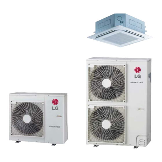
- Page 1 SINGLE ZONE Heat pump 60Hz/R410A 6CSL0-01B (Replaces 6CSL0-01A)
- Page 2 SINGLE ZONE • General Information • Indoor Units • Outdoor Units • Design and installation...
- Page 3 As a part of vertical integration LG makes all the key components in house, which gives an edge to LG to make better and latest technology products with best quality in optimized time.
- Page 4 SINGLE ZONE Step by step SINGLE ZONE system selection process (reference) Calculate or obtain the maximum heat load for the area(s) to be air conditioned Indoor unit specifications Outdoor unit specifications Capacity coefficient factor Air flow and temperature distributions Selection of the control system Control wiring method Description of devices Electrical wiring...
- Page 5 SINGLE ZONE Part 1 General information 1. Model Line up 2. Nomenclature 3. Individual Control System...
-
Page 6: Model Line Up
SINGLE ZONE 1. Model Line up 1.1 Indoor Units Model Name Category Type Chassis Capacity, Btu/h(kW) 24,000 (7.03) 42,000 (12.3) ATNH24GPLE2 [LCN247HV] Ceiling 4way cassette ATNH42GMLE2 [LCN427HV] 1.2 Outdoor Units Btu/h 24,000 42,000 Nominal Capacity 7.03 12.3 AUUW24GD2 AUUW42GD2 Model Names... - Page 7 SINGLE ZONE 2. Nomenclature 2.1 Indoor Units (Global) A T N H 2 4 G P L E 2 Serial number Functions E : Elevation grille Look L : Basic Chassis name Electric ratings (Volts, Phase, Freq) G : 220-240V, 1Ø, 50Hz 208/230V, 1Ø, 60Hz Nominal cooling capacity in kBtu/h 24 : 24kBtu/h...
-
Page 8: Individual Control System
SINGLE ZONE 3. Individual Control System 3.1 Control systems (standard) These controllers will be provided with the respective indoor units. Type Individual controller Applicable model Wired remote controller Ceiling cassette PQRCVSL0QW Heat pump 60Hz/R410A... - Page 9 SINGLE ZONE Part 2 Product data n Indoor units n Outdoor units...
- Page 10 SINGLE ZONE n Indoor units Ceiling cassette 4-way 1.1 List of functions 1.2 Specifications 1.3 Dimensions 1.4 Piping diagrams 1.5 Wiring Diagrams 1.6 Air flow and temperature distributions (reference data) 1.7 Sound levels 1.8 Controller...
-
Page 11: List Of Functions
SINGLE ZONE 1. Ceiling cassette 4-way 1.1 List of functions ATNH24GPLE2 [LCN247HV] Category Functions ATNH42GMLE2 [LCN427HV] Air supply outlet Airflow direction control (left & right) Airflow direction control (up & down) Auto Auto swing (left & right) Air flow Auto swing (up & down) -
Page 12: Specifications
SINGLE ZONE 1. Ceiling cassette 4-way 1.2 Specifications ATNH24GPLE2 ATNH42GMLE2 Model Name [LCN247HV] [LCN427HV] Power Supply V, Ø, Hz 208/230, 1, 60 208/230, 1, 60 Power Input Running Current 0.60 1.00 Casing Color W x H x D 840 × 204 × 840 840 ×... - Page 13 SINGLE ZONE 1. Ceiling cassette 4-way 1.3 Dimensions Heat pump 60Hz/R410A...
- Page 14 SINGLE ZONE 1. Ceiling cassette 4-way Heat pump 60Hz/R410A...
-
Page 15: Piping Diagrams
Thermistor for suction air temperature CN-ROOM Thermistor for evaporator inlet temperature CN-PIPE / IN Thermistor for evaporator outlet temperature CN-PIPE / OUT n Refrigerant pipe connection port diameters [Unit:mm(inch)] Model Liquid ATNH24GPLE2 [LCN247HV] Ø15.88(5/8) Ø9.52(3/8) ATNH42GMLE2 [LCN427HV] Heat pump 60Hz/R410A... -
Page 16: Wiring Diagrams
SINGLE ZONE 1. Ceiling cassette 4-way 1.5 Wiring diagrams Models : ATNH24GPLE2 [LCN247HV] / ATNH42GMLE2 [LCN427HV] Heat pump 60Hz/R410A... -
Page 17: Air Flow And Temperature Distributions (Reference Data)
SINGLE ZONE 1. Ceiling cassette 4-way 1.6 Air flow and temperature distributions (reference data) Models : ATNH24GPLE2 [LCN247HV] Cooling Heating Discharge angle: 40° Discharge angle: 50° Air velocity [ft/s] Air velocity [ft/s] 13ft 10ft 10ft 13ft 13ft 10ft 10ft 13ft Teftperature [°F]... -
Page 18: Table Of Contents
4.9ft the construction(acoustic absorption coefficient) of particular room in which the equipment is installed. - The operating conditions are assumed to be standard. Sound pressure Levels [dB(A)] Model ATNH24GPLE2 [LCN247HV] ATNH42GMLE2 [LCN427HV] Sound pressure level ATNH24GPLE2 [LCN247HV] ATNH42GMLE2 [LCN427HV] NC-65... -
Page 19: Wired Remote Controller
SINGLE ZONE 1. Ceiling cassette 4-way 1.8 Controller Wired remote controller Model name : PQRCVSL0QW (White Color_Supplied) / PQRCVSL0 (Black Color_Accessory) Please attach the inform label inside of the door. Please choose proper language depend on your country. OPERATION INDICATION SCREEN FUNCTION SETTING Button SET TEMPERATURE Button VENTILATION Button... - Page 20 SINGLE ZONE n Outdoor units DC Inverter SINGLE ZONE 1. Power supply 2. List of functions 3. Specifications 4. Dimensions 5. Piping diagrams 6. Wiring diagrams 7. Capacity tables 8. Capacity coefficient factor 9. Operation range 10. Electrical characteristics 11. Field wiring diagram 12.
-
Page 21: Power Supply
SINGLE ZONE 1. DC Inverter SINGLE ZONE 1.1 Power supply Circuit breaker Type Outdoor unit Capacity (kBtu/h) Power supply Voltage range capacity AUUW24GD2 [LUU247HV] 24.0 1Phase MIN.:187 208/230V, 1Ø, 60Hz MAX.:253 Inverter AUUW42GD2 [LUU427HV] 42.0 External wiring procedure - The power supply work is needed only to the outdoor unit. The power supply to the BD unit and the indoor unit is conducted through the communication wiring. - Page 22 SINGLE ZONE 1. DC Inverter SINGLE ZONE 1.2 List of functions AUUW24GD2 AUUW42GD2 Category Functions [LUU247HV] [LUU427HV] Defrost / Deicing High pressure switch Low pressure switch Reliability Phase protection Restart delay (3-minutes) Self diagnosis Soft start Test function Night Silent Operation Wiring Error Check Convenience Peak Control...
-
Page 23: Atnh24Gple2 [Lcn247Hv] Atnh42Gmle2 [Lcn427Hv]
SINGLE ZONE 1. DC Inverter SINGLE ZONE 1.3 Specifications AUUW24GD2 AUUW42GD2 Outdoor unit [LUU247HV] [LUU427HV] Combination ATNH24GPLE2 ATNH42GMLE2 Indoor unit [LCN247HV] [LCN427HV] 2.84 ~ 7.03 ~ 7.81 5.00 ~ 12.3 ~ 13.8 Min.∼Rated∼Max. Cooling Min.∼Rated∼Max. Btu/h 9,700 ~ 24,000 ~ 26,700... - Page 24 SINGLE ZONE 1. DC Inverter SINGLE ZONE AUUW24GD2 AUUW42GD2 Model Name [LUU247HV] [LUU427HV] Power Supply V , Ø , Hz 208/230, 1, 60 208/230, 1, 60 Cooling Max. Starting Current Heating Max. Wiring Connections Power Supply Cable (included Earth) No. x mm (AWG) 3C x 2.5 (12) 3C x 5.0 (10)
- Page 25 SINGLE ZONE 1. DC Inverter SINGLE ZONE 1.4 Dimensions Heat pump 60Hz/R410A...
- Page 26 SINGLE ZONE 1. DC Inverter SINGLE ZONE Heat pump 60Hz/R410A...
- Page 27 SINGLE ZONE 1. DC Inverter SINGLE ZONE 1.5 Piping diagrams Outdoor Unit Inlet Air Temperature Refrigerant Flow Condenser Out Thermistor Temperature Thermistor Cooling Heating Condensing Temperature Thermistor Ø9.52 (3/8) Flare Connection Strainer Strainer 42k model only Liquid Side Piping Electronic Expansion Valve Pressure Sensor...
- Page 28 SINGLE ZONE 1. DC Inverter SINGLE ZONE 1.6 Wiring diagrams Models : AUUW24GD2 [LUU247HV] Models : AUUW42GD2 [LUU427HV] Heat pump 60Hz/R410A...
-
Page 29: Capacity Tables
SINGLE ZONE 1. DC Inverter SINGLE ZONE 1.7 Capacity tables Models : AUUW24GD2 [LUU247HV] + ATNH24GPLE2 [LCN247HV] • Cooling Capacity Indoor Air Temperature : °FDB / °FWB Outdoor Air Temperature 68.0 / 57.2 71.6 / 60.8 77.0 / 64.4 80.6 / 66.2 86.0 / 71.6... - Page 30 SINGLE ZONE 1. DC Inverter SINGLE ZONE Models : AUUW42GD2 [LUU427HV] + ATNH42GMLE2 [LCN427HV] • Cooling Capacity Indoor Air Temperature : °FDB / °FWB Outdoor Air Temperature 68.0 / 57.2 71.6 / 60.8 77.0 / 64.4 80.6 / 66.2 86.0 / 71.6 89.6 / 75.2 °FDB 68.0...
-
Page 31: Capacity Coefficient Factor
(Ti, To) piping Example) • Outdoor unit model : AUUW24GD2 [LUU247HV] • Indoor units (ATNH24GPLE2 [LCN247HV]) • Outdoor temperature : 104℉DB • Indoor temperature: 66.2 ℉WB • Piping length (ODU to IDU):49.2 ft • Indoor unit actual cooling capacity in A room? -
Page 32: Operation Range
SINGLE ZONE 1. DC Inverter SINGLE ZONE 1.9 Operation range Cooling Heating 118.4 Continuous Operation 64.4 Continuous Operation -0.4 59 60.8 91.3 53.6 73.4 77 82.4 Indoor Temp. [°F DB] Indoor Temperature [°F WB] 12 _ Heat pump 60Hz/R410A... -
Page 33: Electric Characteristics
SINGLE ZONE 1. DC Inverter SINGLE ZONE 1.10 Electric characteristics Unit Power Compressor Model Phase Voltage Cooling Heating AUUW24GD2 [LUU247HV] 18.1 31.6 10.0 13.5 0.124 Min.:187, Max.:253 AUUW42GD2 [LUU427HV] 24.1 41.6 15.5 17.5 0.124 x 2 0.6 x 2 Notes : 1. - Page 34 SINGLE ZONE 1. DC Inverter SINGLE ZONE 1.11 Field wiring diagrams 1. All wiring must comply with LOCAL REGULATIONS. 2. Select a power source that is capable of supplying the current as required by the air conditioner. 3. Feed the power source to the unit via a distribution switch board designed for this purpose. 4.
-
Page 35: Sound Pressure Level
SINGLE ZONE 1. DC Inverter SINGLE ZONE 1.12 Sound levels Overall Notes: - Sound measured at 3.3ft away from the center of the unit. - Data is valid at free field condition - Data is valid at nominal operation condition - Reference accoustic pressure 0dB = 20μPa 4.9ft - Sound level will vary depending on a range of factors such as the... - Page 36 SINGLE ZONE Design and installation 1. General installation guideline 2. Guideline for each installation process 3. Installation of indoor unit 4. Installation of outdoor Unit...
- Page 37 SINGLE ZONE 1. General installation guideline 1.1 Installation process & Guideline Striking a balance between system installation & general construction work. Construction work Air conditioning work Setting sleeve and insert work details Preparation of Fitting of steel sleeves contract drawing Moulding box and reinforcement work Sleeve and insert work...
-
Page 38: Installation Procedure
SINGLE ZONE 1. General installation guideline 1.2 Checking the drawing Installation procedure Remarks Check and confirm required loads calculation, Determination of work scope model selection, drawings etc. Preparation of contract drawings Make a relationship between outdoor ,indoor controller and option connection clear. (prepare control circuit diagram) Sleeve and insert works Determine sleeve position, size and... - Page 39 SINGLE ZONE 2. Guideline for each installation process 2.1 Sleeve and insert work 2.1.1 Positioning of the pipe holes 1. The through holes for the drain piping should be positioned such that pipes have a downward gradient (the gradient must be at least 1/100.The thickness of the insulating materials must also be taken into consideration.) 2.
- Page 40 SINGLE ZONE 2. Guideline for each installation process 2.1.3 Sleeve type Sleeve Insulation Pipe NOTE Sleeve type should be considered as per local regulation & laws. CAUTION 1. In high voltage generation places, water-proof flexible conduit should be used. (in substation room, in elevator room) 2.
- Page 41 SINGLE ZONE 2. Guideline for each installation process 2. Support work. Insulated U-bolt type supporting Insulated O-ring band type supporting Bolt Foam resin Bolt 1.5t plate Saddle supporting Supporting interval 1.5(4.92)~2.0(6.56) m(ft) CAUTION During saddle supporting work, insulation should not be pressed by saddle as this can lead to tearing of insulation and thus falling of condensed water during product operation.
-
Page 42: Refrigerant Piping Work
SINGLE ZONE 2. Guideline for each installation process 2.2 Refrigerant piping work 2.2.1 Principles of refrigerant piping The “ principles of refrigerant piping “ must be strictly observed. Cause of problem Action to avoid problem -Rainwater, work water, etc gets into pipes from outside Flushing Pipe covering Vacuum drying... -
Page 43: Flaring Work
SINGLE ZONE 2. Guideline for each installation process 2.2.2 Flaring work Main cause for gas leakage is due to defect in flaring work. Carry out correct flaring work in the following procedure. Cut the pipes and the cable. ① Use the piping kit accessory or the pipes purchased locally. Copper ②... - Page 44 SINGLE ZONE 2. Guideline for each installation process Choice of material for refrigerant piping NOTE Copper pipe selection a. The wall thickness of the refrigerant piping should comply with relevant local and national regulation for R410A the design pressure is 3.8MPa(551.1psi) b.
- Page 45 SINGLE ZONE 2. Guideline for each installation process NOTE Flange connection and procedure 1) Cut the pipe using a pipe cutter. 7) Apply refrigerant oil on the inside and outside of the flared section. (Do not apply SUNISO oil) (Be careful to keep dust away) 2) The cut edge has burrs.
- Page 46 SINGLE ZONE 2. Guideline for each installation process 2.2.3 Pipe connection flaring NOTE CAUTION 1. After installation completion make sure to open the Improper piping and flaring can lead to the leakage of valve. operating the unit with the valve shut off will refrigerant destroy the compressor (Refer to the Additional refrigerant charge detail information)
-
Page 47: Brazing Work
SINGLE ZONE 2. Guideline for each installation process 2.2.4 Brazing work If brazing work is carried out without passing nitrogen gas CAUTION through the pipes then it allows the formation of oxidation bubbles on the inside surface of the pipes. Brazing of refrigerant piping : These oxidation bubbles are then carried along inside the The following precaution should be taken. - Page 48 SINGLE ZONE 2. Guideline for each installation process Brazing work should be carried out either downwards or sideways. An upward direction should be avoided wherever possible(to prevent leakage). over 10(3/8) mm(inch) over 10(3/8) mm(inch) (Expending pipe brazing) (Pipe brazing with socket) (Flare part brazing) (Butt-brazing) Table 1: Correlation of nozzle tip and size of refrigeration piping...
- Page 49 SINGLE ZONE 2. Guideline for each installation process 2.2.5 Refrigerant pipe flushing Flushing is a method of cleaning extraneous matter out of pipes using pressurized gas. NOTE Refrigerant pipe flushing of 3 major effects 1. Removal of oxidation bubbles formed inside copper pipes when “nitrogen replacement is insufficient” during soldering work 2.
-
Page 50: Drain Piping Work
SINGLE ZONE 2. Guideline for each installation process 2.3 Drain piping work The purpose of drain piping is to prevent damage of products and ceiling materials by proper draining of dew condensation which is generated from the evaporator of indoor unit when the hot vapors come in contact with the evaporator. 1. - Page 51 SINGLE ZONE 2. Guideline for each installation process 2.3.1 Drain pipe slope and support • Slope gradient for drain should be 1/50~1/100 and PVC pipes should be used. • Support hanger should be at 1(3.28)~1.5(4.92) (m(ft)) interval to prevent from loosing and dropping. •...
- Page 52 SINGLE ZONE 2. Guideline for each installation process 2.3.2 Drain pipe trap Models with drain pump: 300(11 13/16) or less PVC elbow Max. 800(31-1/2) Flexible hose Common drain pipe Drain pump [Unit : mm(inch)] Polyethylene insulation 10t PVC drain pipe Models without drain pump Metal clamp Flexible drain hose...
- Page 53 SINGLE ZONE 2. Guideline for each installation process 2.3.3 Caution for drain piping work Notice on drain working 1. Drain pipe should be insulated all connected joints and ends. Sharp crook Sharp crook Sharp crook CAUTION Flexible tube should be connected with clamp concentrically. If not, water will leak from the connection.
- Page 54 SINGLE ZONE 2. Guideline for each installation process Drain pipe insulation - Drain pipe should be insulated all connected joints and ends. Insulation Loose fitting Fitting insulation Insulation required wrong insulation not required - Do not use the loose fitting insulation. Drain water leakage test - Water leakage test should be performed 24 hours later after drain work finishing.
-
Page 55: Insulation Work
SINGLE ZONE 2. Guideline for each installation process 2.4 Insulation work 2.4.1 Insulation 1) Operational steps EPDM length should be more Put the pipe in EPDM insulation Bond on both side of cut surfaces Dry it until it becomes thick, sticky longer than pipe length. -
Page 56: Forming The Piping
SINGLE ZONE 2. Guideline for each installation process 2.4.2 Forming the piping 1) Form the piping by wrapping the connecting portion of the indoor unit with insulation material and secure it with two kinds of vinyl tape. • If you want to connect an additional drain hose, the end of the drain outlet should be routed above the ground. Secure the drain hose appropriately. - Page 57 SINGLE ZONE 2. Guideline for each installation process 2.4.3 Essential points of thermal insulation 1) Thermal insulation of refrigerant piping Be sure to give insulation work to refrigerant piping by covering liquid pipe and gas pipe separately with enough thickness heat-resistant insulation materials, so that no gap is observed in the joint between indoor unit and insulating material, and insulating materials themselves.
- Page 58 SINGLE ZONE 2. Guideline for each installation process 3) Insulation tube thickness ① Thickness decision of insulation tube • Insulation material: EPDM or polyethylene foam • Thermal conductivity 0.035 kcal~0.040kcal/m·h°C(0.024~0.027Btu/ft·h℉) • Heat resistance = 212°F(Cooling only) or more 248°F(Heat pump) or over ②...
-
Page 59: Electrical Work
SINGLE ZONE 2. Guideline for each installation process 2.5 Electrical work 2.5.1 Precautions CAUTION When knocking out knock holes • To punch a knock hole, hit on it with a hammer. • After knocking out the holes, we recommend you paint the edges and areas around the edges using paint to prevent rusting. - Page 60 SINGLE ZONE 2. Guideline for each installation process • Use only copper wires. • Make sure to shut down the power before starting the electric wiring work. Do not set ON any switch until the work is completed. • The outdoor unit has an inverter compresser which generates noise and charges the outer casing with the leakag current. The outdoor unit should be grounded so that the effect of the generated noise on othe equipment can be reduced, and that the outer casing can be discharged.
- Page 61 SINGLE ZONE 2. Guideline for each installation process 2.5.2 Control wiring / power supply 1) All wiring must comply with LOCAL REGULATIONS. 2) Select a power source that is capable of supplying the current as required by the air conditioner. 3) Feed the power source to the unit via a distribution switch board designed for this purpose.
- Page 62 SINGLE ZONE 2. Guideline for each installation process Connecting the cable to Outdoor Unit • Remove the side panel for wiring connection. • Use the cord clamp to fix the cord. • Earthing work - Case 1 :Terminal block of Outdoor Unit have mark.
-
Page 63: Checking Method
SINGLE ZONE 2. Guideline for each installation process 2.6 Leakage test 2.6.1 Leakage test CAUTION Air and moisture remaining in the refrigerant system have To avoid nitrogen entering the refrigerant system undesirable effects as indicated below. in a liquid state, the top of the cylinder must be higher ①... - Page 64 SINGLE ZONE 2. Guideline for each installation process 2.6.2 Essential points of testing The key to successful testing is strict adherence to the following procedure: a) The liquid and gas piping in each refrigerant system should be pressurized in turn in accordance with the following steps.
- Page 65 SINGLE ZONE 2. Guideline for each installation process 2.6.3 Checking for leakage [Check 1] (Where pressure falls while carrying out Steps 1 to 3 described on previous page) ▶ Check by measure gage..gas detector. ▶ Check by ear..Listen for the sound of a major leakage. ▶...
- Page 66 SINGLE ZONE 2. Guideline for each installation process 2.7 Vacuum drying works 2.7.1 What is Vacuum drying? Vacuum drying is : The use of a vacuum pump to vaporize(gasify) the moisture (liquid) inside the pipe and expel it leaving the pipes completely dry inside. At 1 atm(760mmHg) the boiling point (evaporating temperature) of water is 100℃(212℉) but if a vacu- um is created inside the pipes using a vacuum pump then the boiling point is rapidly reduced as the degree of the vacuum is increased.
- Page 67 SINGLE ZONE 2. Guideline for each installation process 2.7.2 Evacuation 1. Connect the manifold hose end described in the preceding steps to the vacuum pump to evacuate the tubing and indoor unit. Confirm the "Lo" knob of the manifold valve is open. Then, run the vacuum pump. The operation time for evacuation varies with tubing length and capacity of the pump.
- Page 68 SINGLE ZONE 2. Guideline for each installation process 2.7.3 Choosing a vacuum pump The necessity for counter flow prevention After the vacuum process of the refrigerant cycle, the inside of the hose will be vacuumed after stopping the vacuum pump, the oil of vacuumpump may flow back.
- Page 69 SINGLE ZONE 2. Guideline for each installation process 2) Vacuum pump maintenance Because of their nature, most vacuum pumps contain large amounts of oil which lubricates bearings, etc., and functions to enhance airtightness of pistons. When using a vacuum pump to discharge air from refrigerant piping, moisture in the air tends to get mixed in with the oil.
- Page 70 SINGLE ZONE 2. Guideline for each installation process 2.7.4 Vacuum drying procedure There are two vacuum drying methods and the appropriate one should always be chosen to confirm with individual local conditions. [Normal vacuum drying]..The standard method [Operational steps] 1. Vacuum drying (1st time): Connect a manifold gauge to the service port of the liquid or gas pipe and operate the vacuum pump for at least 2 hours.
-
Page 71: Refrigerant Charging
SINGLE ZONE 2. Guideline for each installation process 2.8 Additional charge of refrigerant 2.8.1 Refrigerant charging instructions Refrigerant charging 1. The results of all calculations must be recorded. (make a list) 2. The refrigerant will need to be additionally charged when the distance between the outdoor Unit and the most distant indoor unit is more than length (refer to section 8 outdoor unit installation condition) 3. -
Page 72: Test Run Procedure
SINGLE ZONE 2. Guideline for each installation process 2.9 Trial test run operation 2.9.1 Test run procedure Check the following before turning power on Wrong power wiring , loosed screws Wrong control transmission wiring , loose screws Piping size , presence of thermal insulation Use a mega-tester Measurement of main power circuit insulation Be sure to record the additional... - Page 73 SINGLE ZONE 2. Guideline for each installation process 2.9.3 Transfer to customer with explanation 1. Operational step Make final report Explain how to Hand over Complete test run (test run operate and relevant printed inspection sheet) maintain equipment materials a) The measurements taken during the test run should be recorded and kept on a test run inspection sheet. b) Do not forget to record the length of the refrigerant piping and the refrigerant additional charging volume on the plate on the back of the outdoor unit external notice board, as this information will be required for servicing the system.
-
Page 74: Installation Of Indoor Unit
SINGLE ZONE 3. Installation of indoor unit 3.1 Ceiling cassette 4-way • Please read the instruction sheets completely before installing the product. • When the power cord is damaged, replacement work shall be performed by authorized personnel only. • Installation work must be performed in accordance with the national wiring standards by authorized personnel only. Anti-bacteria Air Outlet Air Inlet... -
Page 75: Selection Of The Best Location
SINGLE ZONE 3. Installation of indoor unit 3.1.2 Selection of the best location 3.1.3 Precautions regarding cassette indoor unit installation • There should not be any heat source or steam near the unit. • There should not be any obstacles to the air circulation. 1) Main points about the indoor installation •... - Page 76 SINGLE ZONE 3. Installation of indoor unit • Countermeasure: • In case of the multi flow type, use the high humidity kit. Otherwise the dew drops can be seen in the unit body. - Use the carpet on the floor (compared to the tiles the car- pet over it will have a 3 degree rise in temperature) •...
- Page 77 SINGLE ZONE 3. Installation of indoor unit 3.1.4 Ceiling opening dimensions and 1) Install the suspension bolts. hanging bolt location (Use either a W3/8” or M10 size bolt) Use a hole-in anchor for existing ceilings, and a sunken insert, sunken ①...
-
Page 78: Connecting Pipes To The Indoor Unit
SINGLE ZONE 3. Installation of indoor unit 3.1.5 Indoor unit installation < Ceiling work > (2) Adjust the unit to the right position for installation. • Installing of the accessories (except for the decoration (3) Assure that the unit is horizontal. panel) before installing the indoor unit is easier. - Page 79 SINGLE ZONE 3. Installation of indoor unit 3) Indoor unit drain piping • TP/TM Chassis • Drain piping must have downward (1/50 to 1/100): be sure The decoration panel has its installation not to provide up-and-down slope to prevent reverse flow. direction.
-
Page 80: Electric Wiring Work
SINGLE ZONE 3. Installation of indoor unit 2) Wiring Connection CAUTION ① Open the control box cover and connect the Remote Install certainly the decoration panel. controller cord and Indoor power wires. Cool air leakage causes sweating. ‘ Water drops fall. Air conditioner unit Indoor... - Page 81 SINGLE ZONE 3. Installation of indoor unit 3. Do not connect wires of different gauge to the WARNING same grounding terminal. Loose connection may deteriorate protection. • Make sure that the screws of the terminal are not loose. 4. At the unit, keep proper separation between trans- missio and power supply wiring.
-
Page 82: Installation Of Outdoor Unit
SINGLE ZONE 4. Installation of outdoor unit 4.1 Safety Precautions Please strictly follow the instructions given in the Installation manual .Improper installation by ignoring the instructions can lead to damage to life and property. Make sure to read the following safety instructions very carefully and throughly . WARNING This symbol indicates the possibility of death or serious injury. - Page 83 SINGLE ZONE 4. Installation of outdoor unit Be sure to use only those parts which are listed in the svc parts list. Never attempt to modify the equipment. • The use of inappropriate parts can cause an electrical shock, excessive heat generation or fire. Indoor/outdoor wiring connections must be secured tightly and the cable should be routed properly so that there is no force pulling the cable at the connection terminals.
- Page 84 SINGLE ZONE 4. Installation of outdoor unit CAUTION Use two or more people to lift and transport the product. • Avoid personal injury. Do not install the product where it will be exposed to sea wind (salt spray) directly. • It may cause corrosion on the product. Corrosion, particularly on the condenser and evaporator fins, could cause product malfunction or inefficient operation.
- Page 85 SINGLE ZONE 4. Installation of outdoor unit 4.1.1 Points for explanation about operations The items with WARNING and CAUTION marks in the operation manual are the items pertaining to possibillties for bodily injury and material damage in addition to the general usage of the product. Accordingly, it is necessary that you make a full explanation about the described contents and also ask your customers to read the operation manual.
- Page 86 SINGLE ZONE 4. Installation of outdoor unit 4.1.4 For the following items, take special care during construction and check after installation is finished 1. Items to be checked after completion of work Unit Items to be checked If not properly done, what is likely to occur Check Are the indoor and outdoor unit fixed firmly? The units may drop, vibrate or make noise.
-
Page 87: Before Installation
SINGLE ZONE 4. Installation of outdoor unit 4.1.5 Before installation • During product unpacking and removing it from the packing case, be sure to lift it without exerting any pressure on other parts, especially, horizontal flaps, the refrigerant piping, drain piping, and other resin parts. •... -
Page 88: Lifting Method
SINGLE ZONE 4. Installation of outdoor unit 4.2 Introduction This installation guidance describes the procedures for outdoor unit installation, piping, wiring, and control between outdoor units, indoor units and controller. Installation of the indoor units is not described in this part. Please refer to the installation guidance manual which supplied with indoor units for their respective installation. - Page 89 SINGLE ZONE 4. Installation of outdoor unit 4.3 Foundation SINGLE ZONE For good drain of outdoor unit, keep the bottom height from icing upward. AUUW24GD2 [LUU247HV] <Basic intensity> Bolt Factor M10-J type Concrete height 200(7-7/8)mm(inch) or more Bolt inserted depth 70(2-25/32)mm(inch) or more AUUW42GD2 [LUU427HV] <Basic intensity>...
- Page 90 SINGLE ZONE 4. Installation of outdoor unit 4.4 Settlement of the outdoor unit • Anchor the outdoor unit with a bolt and nut tightly and horizontally on a concrete or rigid mount. • When installing on the wall, roof or rooftop, anchor the mounting base securely with a nail or wire assuming the influence of wind and earthquake.
- Page 91 SINGLE ZONE 4. Installation of outdoor unit 4.5 Selection of the best location This SINGLE ZONE unit is suitable for installation in a residential and commercial environmental situation. If installed near a household appliance it can cause electromagnetic interference. The units should be installed in a location that meets the following requirements: 1.
- Page 92 SINGLE ZONE 4. Installation of outdoor unit 4.6 Clearance space 4.6.1 Clearance around outdoor unit SINGLE ZONE 300(11-13/16) 300(11-13/16) or more or more 300(11-13/16) 300(11-13/16) 300(11-13/16) 300(11-13/16) or more or more or more or more • Ensure that the space around the back is more s t a s t a 300(11-13/16)
- Page 93 SINGLE ZONE 4. Installation of outdoor unit Clearance of side discharge unit [Unit:mm(inch)] 1) Where there is an obstacle on the air intake side: n No obstacle above • Obstacle on the suction side only • Obstacle on the both sides n Obstacle above, too •...
- Page 94 SINGLE ZONE 4. Installation of outdoor unit n Where the obstacles on the discharge side is lower than the unit: • No obstacle above • Obstacle above, too ʻLʼ should be lower than ʻHʼ. Close the bottom of the installation frame to prevent the discharged air from being bypassed.
- Page 95 SINGLE ZONE 4. Installation of outdoor unit 4.7 Outdoor unit piping 4.7.1 Outdoor unit piping Required tools Torque Wrench Screw Driver Drill M/C f 3.5/F14.5 Measuring Tape, Blade Core drill Spanner Soap Foam Thermometer Hexagonal wrench(4mm, 5mm) Hook Meter Multi Tester Flare Set 4.7.2 Connecting piping Tighten the flare nut with torque wrench until the wrench clicks.
- Page 96 SINGLE ZONE 4. Installation of outdoor unit 4.8 Outdoor unit installation requirments 4.8.1 Piping elevation and length Pipe Size Length A Elevation *Additional Unit : mm(inch) Unit : [m(ft)] Unit : [m(ft)] refrigerant Capacity Unit: g/m(oz/ft) Liquid Standard Max. Standard Max.
- Page 97 SINGLE ZONE 4. Installation of outdoor unit 4.9 Outdoor unit cabin 4.9.1 Outdoor Cabin louver requirement 1. Outdoor cabin type : Manual door open type Max15 (Recommended) 2. Louver angle : less than 15° on the horizontal base 3. Louver interval: over 100(3-15/16) mm(inch) (recommend) Over 100(3-15/16) mm(inch) (Recommended) 4.
- Page 98 Yeouido P.O.Box 335 Seoul, 150-721, Korea. http://www.lgeaircon.com All rights reserved The air conditioners manufactured by LG have received ISO9001 certificate for Printed in Korea December / 2012 quality assurance and ISO14001 certificate for environmental management system. The specifications, designs, and information in this brochure are subject to change without notice.